Page is loading ...

I-EV2D-02.doc Issue 12 01/01/2021 1
IOM – EVOLUTION II - ZONE 1 FLOODLIGHT
INSTALLATION, OPERATION AND MAINTENANCE INSTRUCTIONS
Evolution II & Evolution II LT (Low Temperature)
Floodlight Luminaires
ATEX & IECEx
Important: Please read these instructions carefully before installing or maintaining this equipment.
Good electrical practices should be followed at all times and this data should be used
as a guide only.

I-EV2D-02.doc Issue 12 01/01/2021 2
IOM – EVOLUTION II - ZONE 1 FLOODLIGHT
Type Of Protection Ex d e mb (flameproof and increased safety, encapsulation), Ex tb (dust)
Protection Standards (IEC) EN 60079-0, 60079-1, 60079-7, 60079-18, EN 60079-31.
Area Classification Zone 1 and Zone 2 areas to (IEC) EN 60079-10-1
Zone 21 and Zone 22 areas to (IEC) EN 60079-10-2
Installation (IEC) EN 60079-14
Certificate Evolution ll Evolution ll LT
IECEx Certificate of Conformity
IECEx BAS05.0045X
EC Type Examination Certificate
Baseefa04ATEX0155 (X applies to 120V
version)
IECEx Certificate of Conformity
IECEx BAS05.0044X
EC Type Examination Certificate
Baseefa04ATEX0192 (X applies to 120V version)
Equipment Coding Ex d e mb IIB T3/T4 -20oC Ta T*oC
Ex tb IIIC T**oC Db IP6X
(see table 0 for details)
Ex d e mb IIB T3/T4 -50oC Ta T*oC
Ex tb IIIC T**oC Db IP6X
(see table 0 for details)
ATEX Coding II 2GD
Ingress Protection IP66/67 to EN/IEC 60529
CE Mark
The CE marking of this product applies to "The Electrical Equipment (Safety) Regulations
2006", "The Electromagnetic Compatibility Regulations 2004", the “Waste Electrical and
Electronic Equipment Regulations 2006” and the "Equipment and Protective Systems intended
for use in Explosive Atmospheres Regulations 1996". [This legislation is the equivalent in UK
law of EU directives 2014/35/EU, 2014/30/EU, 2012/19/EU and 2014/34/EU respectively].
The Equipment is declared to meet the provisions of the ATEX directive (2014/34/EU)
by reason of the EC Type Examination and compliance with the Essential Health and
Safety Requirements.
M Poutney Technical Manager
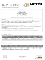
1.0 Introduction – Evolution II LT Asymmetric ATEX Floodlight
The Evolution II is a development of the existing Evolution floodlight that has improved performance while
retaining the best features of the Evolution. The lamp is contained in an enclosure with the cover glass
permanently attached. The cover retaining screws have their heads filled and must not be removed. (This would
invalidate the certificate).
The mains terminals and Ex e protected ballast are contained in an Ex e chamber on the end of the luminaire.
This is accessed by a hinged cover held by a single bolt. Inside this chamber is an Ex d enclosure built into the
main body casing which contains a power factor correction capacitor (optional).
The ignitor is contained with the lampholder in an Ex d assembly, which is retained in the end wall of the lamp
enclosure using a bayonet arrangement locked in place by the chamber fastening screw. The supply to this
housing is through a cable, which can also be used to select the tapping. The ranges of lamps, which can be
catered for, are 150, 250 and 400W SON/T and MBI/T, 600W SON/T with remote ballast and 500W T/HAL with
E40 and R7s lamp caps. Wide (mottled) and narrow (specular) beam reflectors are available. These must be
specified when ordering.
In addition there is a low voltage version which has a 2:1 step-up transformer mounted into an enlarged end cap.
This allows the use of power supplies in the range 110-120V 50/60 Hz. On this version access to the gear
chamber is by removing a single bolt at the edge of the end cap.
SPECIAL CONDITIONS FOR SAFE USE
The 120V version of this product must only be mounted so that the fastening points are at the same
height as each other, i.e. it must be mounted horizontally not on its side. Please refer to the product
certificate for further information

I-EV2D-02.doc Issue 12 01/01/2021 3
IOM – EVOLUTION II - ZONE 1 FLOODLIGHT
Note: The range of lamps available is as indicated in TABLE 0.
A range of mounting accessories is also available.
2.0 Storage
Luminaires and control gearboxes are to be stored in cool dry conditions preventing ingress of moisture and
condensation.
3.0 Installation and Safety
3.1 General
There are no health hazards associated with this product whilst in normal use. However, care should be
exercised during the following operations. Installation should be carried out in accordance with BS EN 60079-14
or the local hazardous area code of practice, whichever is appropriate, and fitting of specified insulating material
to be adhered to where a specific fire resistance rating is required.
In addition any applicable local regulations must be observed. The luminaires are Class 1 and should be
effectively earthed.
The luminaires are heavy and suitable means of handling on installation must be provided.
Certification details on the rating plate must be verified against the application requirements before installation.
The information in this leaflet is correct at the time of publication. The company reserves the right to make
specification changes as required.
3.1.1 Use in Combustible Dust Atmospheres
Where the equipment is used in ignitable dust atmospheres reference must be made to the selection and
installation standards in order that the equipment is used correctly. In particular this applies to the de-rating of
surface temperature for use where dust clouds may be present. Dust layers should not be allowed to accumulate
on the fitting surface and good housekeeping is required for safe operation. Dust in layers has the potential to
form ignitable clouds and to burn at lower temperatures.
Refer to EN (IEC) 60079-10-2 & EN (IEC) 60079-14 for additional details of selection and installation.
3.1.2 Hybrid Mixtures – Gas and Dust
Where hybrid mixtures exist as a potentially explosive atmosphere, consideration should be given to verifying that the
maximum surface temperature of the luminaire is below the ignition temperature of the hybrid mixture.
3.2 Tools
4, 5, 6mm A/F socket keys.
3mm and 5mm flat blade screwdriver.
19mm and 13mm A/F spanner.
Suitable spanners for installing cable glands.
Pliers, knife, wire strippers/cutters.
3.3 Electrical Supplies
The supply voltage and frequency should be specified when ordering. A maximum voltage variation of +6%/-6%
on the nominal is expected. (The safety limit for T rating is +10%). Luminaires should not be operated
continuously at more than +6%/-10% of the rated supply voltage of the control gear or tapping. The user must
determine the actual underlying site supply and purchase or adjust accordingly. In this case, the luminaires have
multi-tapped control gear that can be set to a range of 50 and 60 Hz voltages. Different ballasts are used for 50
and 60 Hz. The tappings are shown on the control gear and the limits are shown on the rating plate. They are
selected by changing the position of the wire feeding the ballast. The low voltage version feeds the ballast via
the transformer and for simplicity the ballast selection tappings are shown as 110/115/120V which represents the
incoming mains supply voltage not the volts into the ballast.
If the equipment is located in sections of the system where the voltage is higher or lower than nominal, an
appropriate voltage tap should be selected, but care must be taken to log or mark the equipment so that the
tapping is re-set if the equipment is re-located. If in doubt, tappings should be set on the high side. 10V
maximum drop below nominal is desirable for HPS and advised for MBI. The light output will be reduced. The
figures given are at the luminaire. Where MBI/Metal Halide lamps are used, the tapping must be set accurately
for best performance.

I-EV2D-02.doc Issue 12 01/01/2021 4
IOM – EVOLUTION II - ZONE 1 FLOODLIGHT
Where shore or construction site supplies are used, which are different to the service supplies, the tappings
should be re-set. If not, advice on the effect of these temporary supplies should be sought from the Technical
Department.
3.4 Lamps
All the HPS lamps used in this range are of a standardised type and there is no preference between makes, or in
the case of HPS, colours. The cap is E40. The luminaire uses tubular lamps. If mixed installations are used, care
must be taken to ensure that the correct lamp is fitted on installation and replacement. The 250W MBI lamp is
the 3.A type that runs on a SON ballast. The control gear supplied for the 400W MBI lamp is designed to run the
standard "SON compatible" OSRAM lamp which has a current rating of 4.2A. Other SON compatible lamps may
be used. The obsolete 3.5A 400W Metal halide lamp must not be used in this luminaire. HPS lamps
substantially maintain their light output to the end of their electrical half life, which can be up to 24,000 hours.
However, lamp replacement at around 16,000 hours is desirable to avoid piecemeal replacement on a large
scale. MBI lamps have a shorter life and higher lumen depreciation, HPS and MBI lamps should be replaced
shortly after they do not light. The ignitor will attempt to strike the lamp for 20 minutes after power is first
applied. If the lamp does not strike within this period then ignition attempts will be stopped until power is
switched off and on again. Also see section 4.0.
The above information is current at the time of publication. The development of lamps and control gear is
ongoing and detailed advice on lamp performance can be obtained from the Technical Department or the lamp
supplier.
Incandescent lamps and tungsten halogen must be selected for the supply voltage. Running at over the rated
supply voltage will reduce life and at greater than +10% will compromise the T rating.
Important: HPS and MBI circuits should not be energised without a lamp fitted. HPS & MBI lamps
with internal ignitors must not be used.
3.5 Mounting
Luminaires should be installed where access for maintenance is practical and in accordance with any lighting
design information provided for the installation. This will usually consist of aiming points and aiming angles. The
mounting arrangements should be secured with lock washers or self locking nuts and bolts.
When the luminaire is mounted vertically it is recommended that the gear compartment should be facing
downwards.
The luminaire is provided with a mechanism to adjust and lock the floodlight to 5-degree intervals. The outer ring
of holes in the adjustment disc gives increments of 30 degrees, this is the coarse adjustment, and is used
second. The inner ring has 6 holes giving offsets of plus 0,5,10,15,20 or 25 degree on the 30-degree increments,
this setting is used first. The numbers indicate the degrees but the holes are not in order. They can be viewed
through the hole in the mounting bracket. The unit is set up with the terminal cover end tightened enough to
allow the unit to be moved smoothly. Fine adjustment is made by selecting the correct hole and loosely fixing in
the mounting bracket. The pivot bolt is then tightened still, allowing controlled movement. The bolt securing disc
to case is unscrewed from the case and reinserted when the coarse adjustment gives the required correct angle.
When everything is correct all bolts are fully tightened. Main pivot 30Nm, case bolt 16Nm, bracket bolt 20Nm.
Example 1: Inner ring set at '0', then by moving the outer ring, 0º, 30º, 60º angles are achieved. Example 2:
Inner ring set at '5', then by moving the outer ring, 5º, 35º, 65º angles are achieved.
When the luminaire is mounted using the pendant mount bracket arrangement, the brackets must be mounted
on a horizontal surface with the luminaire aimed glass downwards. The minimum distance between the luminaire
and illuminated surface, directly in front of the luminaire, is 1 metre.
3.6 Cabling and Cable Glands
3.6.1 Cables
The cable entry temperatures are given as the rise over the maximum rated ambient (Tamb). This allows the
user to adjust the cable specification for actual maximum site ambient.
The maximum conductor size is 6mm². Internal and external earth points are provided. 300/500V cable ratings
are adequate and no special internal construction is necessary as the terminations are Ex e. The standard
looping cable size is 6mm². The selection of cable size must be suitable for the fuse rating. Some guidance on
this is given below. The fuse ratings apply to the circuit on the supply side of the control gear.

I-EV2D-02.doc Issue 12 01/01/2021 5
IOM – EVOLUTION II - ZONE 1 FLOODLIGHT
3.6.2 Cable Glands
This apparatus is certified to EN 50014: 1997, EN 50018: 2000, EN 50019: 2000 and EN 50281-1-1:1998.
Cable glands for entry into Ex e enclosures when fitted with any gland to body sealing method and the supply
cable, must reliably maintain the IP rating of the enclosure with a minimum value of IP54. The cable gland must
withstand an impact value of 7Nm or 4Nm where the risk of mechanical damage is low.
Sealing plugs must be similarly rated and a tool must be required for their removal. Where the cable is not
reliably clamped externally to the apparatus, the cable gland must clamp the cable against a pull in Newtons of
20 x the cable OD in mm for non-armoured cable and 80 x the cable OD for armoured cable. Cable glands must
be ATEX certified. Two tapped cable entries are provided, one with a plug and seal suitable for permanent use,
the other has a travelling plug. M20 x 1.5 entries are standard, with M25 available on request. Where brass
cable glands are used in corrosive environments cadmium or nickel plating should be used.
3.7 Cable Connection
The cable connections are made by slackening the end cover bolt and swinging the cover to one side, it can be
latched in place by sliding the hinge point. The conductors should be bared back so that they make full contact in
the terminals, but the bare conductor should not be more than 1mm beyond the terminal. Unused terminal
screws should be tightened. The core must be identified by polarity and connected in accordance with the
terminal markings. Before re-fitting the cover, a final check on the correctness of connections should be made.
Cover bolt torque 10Nm.
3.7.1 Selecting the Tapping
The tapping is set on the supply side of the ballast terminal block, the supply wire going to the appropriate tap
and the voltages are shown on the ballast label. The ignitor connection goes into the two terminals next to the
ignitor housing, the blue connection is always to the end neutral terminal, the live brown connection goes into the
second terminal. The luminaire is factory set at the highest tapping, or that given with the order. The tapping
suitable for the supply is selected or confirmed on installation. The unused connection terminals are to be fully
tightened to prevent incorrect selection during initial lamp installation or relamping.
3.8 Fitting lamps
Isolate the supply before opening the end cover. Make sure the correct lamp is selected as detailed above.
Access for fitting lamps is gained through the end hinged cover. The ignitor cable connections are unscrewed
and the ignitor housing turned anti-clockwise to release. The ignitor housing fixing screws are thread locked into
place and are not to be removed in service. The lamp should be firmly screwed into place and the housing
replaced. Reconnect the cables, make a final check on the tapping and mains terminals then close the hinged
cover and tighten fastening bolt. (The front cover is permanently fixed. The bolts have been covered with a hard
setting resin to prevent removal, which would invalidate the certificate). Note that the end cover will not close
unless the ignitor/lamp housing is in its correct position.
3.9 Inspection and Maintenance
Visual inspection should be carried out at a minimum of 12 monthly intervals and more frequently if conditions
are severe, refer to (IEC) EN 60079-17. The time between lamp changes could be very infrequent and this is
too long a period without inspection.
3.9.1 Routine Examination
The equipment must be de-energised before opening and note taken of the rated opening delay period, 15
minutes if there is a hazardous atmosphere present. Individual organisations will have their own procedures.
What follows are guidelines based on (IEC) EN 60079-17 and on our experience:
1 Ensure the lamp is lit when energised and that the lampglass is not damaged.
2 When de-energised and left to cool, there should be no significant sign of internal moisture. If there are
signs of water ingress, the luminaire should be opened up, dried out, and any likely ingress points
eliminated by re-gasketing, re-greasing or other replacement.
3 Check the terminal chamber gasket for any damage or permanent set and replace as required, the gasket is
held in place by a few spots of silicone RTV.
4 Check the tightness of glands and blanking plugs.
5 Check any external earthing.

I-EV2D-02.doc Issue 12 01/01/2021 6
IOM – EVOLUTION II - ZONE 1 FLOODLIGHT
6 Examine the front glass for any signs of damage. If thought necessary, the fillet of silicone sealant can be
re-sealed with a proprietary brand of clear RTV silicone. If the glass is damaged the luminaire must be
returned for servicing.
7 The terminal chamber should be opened periodically and checked for moisture and dirt ingress. The cable
connections should be checked for tightness. The gasket should be checked for cracks or lack of elasticity,
and if necessary, replaced. Cover bolt torque: 10Nm.
8 The ignitor housing flameproof path is cylindrical and can not be readily checked, it will not go out of shape.
The ignitor housing securing bolts are designed to be fixed in place and must not be removed. When
relamping, make sure the flameproof spigot path is free of dirt and slides into place smoothly. A little
molybdenum spray (Dow Corning MOLYKOTE) can be used.
9 Check that mountings are secure and the adjusting disc bolts are tight.
10 Clean the lampglass.
11 If it has been suspected that the luminaire has mechanical damage, a stringent workshop overhaul will be
required. Where spares are needed, these must be replaced with factory specified parts. No modifications
should be made without the knowledge and approval of the manufacturer.
4.0 Electrical Fault Finding and Replacement
Any fault finding must be done in a safe manner by a competent electrician with the luminaire isolated and, if
carried out with the luminaire in place, under a permit to work.
The checklist for fault finding is as follows:
1. Check operation with a known working lamp
2. Check all electrical wires and connections.
3. Check the mains voltage at the incoming terminal blocks.
4. Replace the ignitor housing with a known working part
5. Replace the ballast with a known working part.
Fault finding by substitution is the normal way to identify faulty components. In the first 20 minutes after power is
applied the ignitor will attempt to ignite the lamp with high voltage pulses. This may be heard as a buzzing sound
from the ignitor housing. A bad contact at the lamp cap will show evidence of arcing and heat damage at the
contact. If the ballast is fault signs of overheating may be found such as discoloration of the ballast paint. The
ballast is fitted with a non self-resetting thermal cut-out that will open the circuit if the temperature of the ballast
exceeds a safe value. This cut-out will then reset when the mains is switched off and on again and the ballast
has had time to cool. The transformer (if fitted) is also fitted with a non-self resetting thermal cut-out. A faulty
capacitor will result in either fuses or MCB’s being tripped or an increased current taken from the mains supply
(open circuit failure). Before re-assembling, all connections should be checked and any damaged cable
replaced.
5.0 Fuse Ratings
The fuse ratings for HID lamp circuits need to take account of three components of circuit current.
1) Current inrush to PFC capacitors which can be up to 25 x the rated capacitor current and last 1-2
milliseconds
2) Lamp starting current including steady capacitor current which together may decline from up to 200% of
normal at 10 seconds after switch-on to normal after 4 minutes.
3) Rectification effects caused by asymmetrical cathode heating for a few seconds after starting, this effect is
random and very variable.
With the availability of MCB's with a wide range of characteristics, the individual engineer can make a better
judgement of what is required. Use MCB's suitable for inrush currents to reduce ratings. The normal capacitor
current will probably be the determining factor, 0.076A per µF at 240V, 50Hz (adjust for other voltages by
multiplication, x 6/5 for 60Hz). For HBC fuses use 1.5 x normal capacitor current. All calculations must satisfy
wiring regulations. For Tungsten Halogen inrush use 8 x rated current.
For the low voltage version the use of slow blow type fuses or MCB’s are recommended to allow for the inrush of
the transformer.

I-EV2D-02.doc Issue 12 01/01/2021 7
IOM – EVOLUTION II - ZONE 1 FLOODLIGHT
Note: For starting and running currents for 240V/120v, 50Hz using internal control gear see TABLE 1.
Conventional matrix for HBC fuses is outlined in TABLE 2.
6.0 Disposal of Material
The unit is mostly made from incombustible materials. The capacitor is of the dry film type and does not contain
PCB's. The control gear contains plastic parts and polyester resin. The ignitor contains electronic components
and synthetic resins. All electrical components may give off noxious fumes if incinerated. Take care to render
these fumes harmless or avoid inhalation. Any local regulations concerning disposal must be complied with. Any
disposal must satisfy the requirements of the WEEE directive [2012/19/EU] and therefore must not be treated as
commercial waste. The unit is mainly made from incombustible materials. The control gear contains plastic,
resin and electronic components. All electrical components may give off noxious fumes if incinerated.
6.1 Lamps
Incandescent lamps and discharge lamps in modest quantities are not "special waste". The outer envelope
should be broken in the container to avoid injury.
This applies to the UK, there may be other regulations on disposal operating in other countries.
Re-cycling facilities are also becoming available.
Important: Do not incinerate lamps.
Tables 0/1/2
Table 0 Maximum Ambient and Temperature Ratings Refer to Section: 1.0
Lamp Wattage Tamb
T*ºC
T Class Dust Rating
T**0C
Cable Rating
ºC
Cable Rise ºC
T/HAL
(
E40
)
500W 40 T3 195 90 50
T/HAL
(
R7s
)
500W 55 T3 195 80 40
SON/T 150 40 T4 130 80 40
SON/T 150 55 T3 175 90 35
SON/T 250 40 T4 130 80 40
SON/T 250 55 T3 175 90 35
SON/T 400 40 T3 175 80 40
SON/T 400 55 T3 175 95
(
100
)
40
(
45
)
SON/T 600 35 T3 195 90 55
MBI-T 150 40 T4 130 80 40
MBI-T 150 55 T3 175 90 35
MBI-T 250 40 T4 130 80 40
MBI-T 250 55 T3 175 90 35
MBI-T 400 40 T3 175 80 40
MBI-T 400 55 T3 175 90
(
100
)
35
(
45
)
Figures in brackets indicate the values for the low voltage version where they are different to the 240v version
To comply with the Waste Electrical and Electronic Equipment directive 2012/19/EU the
apparatus cannot be classified as commercial waste and as such must be disposed of or
recycled in such a manner as to reduce the environmental impact.

I-EV2D-02.doc Issue 12 01/01/2021 8
IOM – EVOLUTION II - ZONE 1 FLOODLIGHT
Table 1 Starting and Running Currents Refer to Section : 5.0
Lamp Lamp A Start A Run A Capacitance µF Circuit Power (W)
150W HPS 1.8 1.45 (3.1) 1.0 (2.0) 20 177
250W HPS 3.0 2.35
(
4.9
)
1.4
(
2.8
)
30 285
400W HPS 4.6 4.0
(
7.8
)
2.1
(
4.2
)
40 435
600W HPS 6.8 5.6 2.8 60 621
150W MBI 1.8 1.6
(
3.1
)
1.0
(
2.0
)
20 177
250W MBI 3.0 2.7
(
4.9
)
1.45
(
2.8
)
30 285
400W MBI 4.2 4.0
(
7.8
)
2.1
(
4.2
)
40 435
Figures shown at 240V 50Hz.
Figures in brackets indicate currents for the low voltage version at 120V 50Hz.
Notes: Minimum power factor correction: 0.85.
The start and run currents are corrected.
Table 2 Fuse Ratings Refer to Section : 5.0
Lamp Wattage
Number of Lamps
1 2 3 4 5 6
150W 4
A
6
A
10
A
10
A
16
A
16
A
250W 10
A
16
A
16
A
20
A
20
A
20
A
400W 16
A
20
A
20
A
25
A
25
A
32
A
600W 16
A
20
A
25
A
32
A
32
A
40
A
For low voltage version increase fuse sizes by a factor of two.

I-EV2D-02.doc Issue 12 01/01/2021 9
IOM – EVOLUTION II - ZONE 1 FLOODLIGHT
EU-Declaration of conformit
y
UE-Déclaration de conformité
EU-Konformitätserklärung
Manufacturer Chalmit Address 388 Hillington Road, Glasgow. G52 4BL Scotland UK
Product Evolution ll & Evolution ll LT Floodli
g
ht
EC - T
y
pe Examination Certificate BAS04ATEX0192, BAS04ATEX0155
(
X added to 120V versions
)
.
Notified Body SGS FIMKO OY 0598
ATEX Coding II 2 GD ATEX Classification Group II Category 2 GD
Equipment Coding BAS04ATEX0192 BAS04ATEX0155
Ex d e mb IIB T3/T4 -50oC Ta T*oC
Ex tb IIIC T**oC Db IP6X
Ex d e mb IIB T3/T4 -20oC Ta T*oC
Ex tb IIIC T**oC Db IP6X
Ingress Protection IP66/67
The technical basis, with respect to equivalence of
La base technique, en ce qui concerne l'équivalence de
Die technische Grundla
g
e hinsichtlich der Normen
Protection Standards EN 60079-0, EN 60079-1, EN 60079-7,EN 60079-18, EN 60079-31.
Area Classification EN 60079-10-1and EN 60079-10-2
of compliance with the EHSRs is valid as there are no changes which materially affect the state of technological progress of the product.
en conformité avec les EESS est valide puisqu'il n'y a aucun changement qui affecte matériellement l'état de l'évolution technologique du
produit.
zur Erfüllun
g
der GSGA ist
g
e
g
eben, da keine Änderun
g
en erfol
g
t sind, die einen Einfluss auf den technischen Stand des Produkts haben.
Terms of the directive: Standard & Date Certified to Standards Date Declared to
Prescription de la directive: Standard & date certifiée à Normes date Déclaré
Bestimmungen der Richtlinie: Standard & Datum
Zertifiziert nach
Standards Datum erklärt
2014/34/EU Equipment and protective systems intended for use in
potentially explosive atmospheres.
EN 60079-0: 2012
EN 60079-1: 2007 2014
2014/34/UE Appareils et les systèmes de protection destinés à être
utilisés en atmosphères potentiellement explosibles.
EN 60079-7: 2007
EN 60079-18: 2009
2015
2015
2014/34/EU Geräte und Schutzsysteme zur bestimmungs-
g
emäßen Verwendun
g
in explosionsfähi
g
en Bereichen.
EN 60079-31: 2008 2014
2014/30/EU Electroma
g
netic compatibilit
y
EN 55015 : 2013
2014/30/UE Compatibilité électroma
g
nétique EN 61547 : 2009
2014/30/EU Elektromagnetische Verträglichkeit EN 61000-3-2 : 2014
2014/35/EU Low volta
g
e equipment EN 60598-1 : 2015
2014/35/UE Équipements électriques à bas voltage EN 60598-2-5 : 2015
2014/35/EU Niederspannun
g
s
g
eräte / -s
y
steme EN 60529 : 1992
2012/19/EU Waste of electrical and electronic equipment
2012/19/UE Déchets d'équipements électriques et électroniques
2012/19/EU Entsorgung der elektrischen und elektronischen Geräte
/ S
y
steme
2011/65/EU RoHS II Directive

I-EV2D-02.doc Issue 12 01/01/2021 10
IOM – EVOLUTION II - ZONE 1 FLOODLIGHT
On behalf of the Chalmit, I declare that, on the date the equipment accompanied by this declaration is placed on the market, the equipment conforms to all
technical and re
g
ulator
y
requirements of the above listed directives.
En tant que représentant du fabricant Chalmit, je déclare qu'à la date où les équipements accompagnant cette déclaration sont mis sur le marché, ceux-ci
sont conformes à toutes les dispositions réglementaires et techniques des directives énumérées ci-dessus.
Hiermit bestätige ich, im Namen von Chalmit, dass am Tag der Lieferung des Produkts/der Produkte zusammen mit dieser Erklärung das Gerät/die Geräte
alle technischen und regulativen Anforderungen der oben aufgeführten Direktiven erfüllt.
Name and Date Mark Poutney 01/01/2021 Technical Manager
Nom et Date Directeur technique
Name und Datum Technischer Leiter
Qualit
y
Assurance Notification b
y
: SGS FIMKO OY Qualit
y
Mana
g
ement S
y
stem Acreditation: ISO 9001
Notification d'assurance qualité par: 0598 S
y
stème de Mana
g
ement Qualité Accréditation:
Qualitätssicherungsnotifikation durch: Qualitätsmanagementsystem Akkreditierung:
Environmental Mana
g
ement S
y
stem. ISO 14001
S
y
stème de
g
estion de l'environnement.
by
/par/durch
Umwelt kontroll system. Loyd's Register
Certificate No./Certificat N°/Zertifikat Nr. LRQ 4005876
`
/