Page is loading ...

-1 0
=
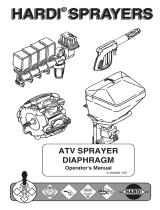
SX-MD18
E Electric Sprayer
User’s Manual
Notice to Users
The User’s Manual is a part of the Sprayer. Please
keep it in good conditions. In order to utilize and maintain
the product in good manner, please read the User’s Manual
carefully before operation. If you have any doubt, contact
the supplier.
The Sprayer shall be operated, maintained and
repaired by persons who are familiar with its
performance and know how to operate in a safe manner.
The manufacturer shall not be liable for decreased
reliability, machine damage and human injury arising from
unauthorized modification of the Sprayer.

1 2
=
Table of Contents
I. Product Overview………………………………1
II. Structure and Features…………………………2
III. Technical Parameters…………………………4
IV. Precautions …………………………………4
V. How to Operate the Sprayer……………………8
VI.Recommended pesticide and spray head operation…15
VII.Structural Diagram and Schedule…………………17
VIII. Cleaning and Maintenance………………………20
IX.Storage…………………………………………21
Ⅹ. Troubleshooting ………………………………22
Ⅺ. Packing List ………………………………………23
I. Product Overview
This Sprayer is one of our electric sprayer series
elaborately designed to reduce labor and increase spraying
performance in a bid to meet the demands of market.
Thanks to its novel design, unique appearance , smooth
outline , safe and high-performance operation, in addition
to easy carrying either by dragging or back-mounting, the
Sprayer is a an ideal upgraded and updated product of
traditional sprayers , especially fit for pest-controlling of
various crops, flowers and garden plants,cleaning of
public places as well as hygiene and disease control of
fowl and livestock houses.
The Sprayer is equipped with a micro diaphragm pump
and a 12V/7Ah battery as the power source to reduce the
labor significantly and attain an efficacy 3~4times higher
than that of manpower , amongst other advantages such as
its high pressure, uniform atomization, high penetration
and attachment of droplets .

3 4
=
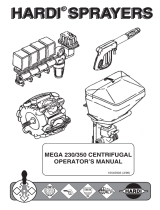
II. Structure and Features
Structure: The Sprayer is composed of a spray tank , a
back cover , a battery , a diaphragm pump , spraying
parts ( rubber hose , switch , spray boom and
spraying nozzle ), a strap , a trailer , etc.
Features:
① The spray tank is designed to be concise and
elegant , capable of mating with the trailer ,
easy to disassemble and assemble.
② Come with a high-pressure and large flow pump
to work with nozzles of various functions and
an easy pressure-regulation unit to vary the
atomization pressure between 2-4.5 bar ,so as
to satisfy the demands of various operation
types and various nozzles, and attain the
purpose of cost-saving and high efficiency.
③ Come with a micro diaphragm pump of compact size,
light weight, high pressure , even atomization, good
penetrability,high adhesion ratio, extended service life
as well as a reliable overload protection.
④ Come with a high-precision voltmeter and
low-battery alarm circuit for precise and
clear indication of battery voltage . The alarm
will give warning when the battery voltage falls
below 10.8-10.5V, so as to prevent against
lower-power working or power-free storage of
battery, and keep the battery pole plate from
getting degraded, contributing to the
extended service life of battery.
⑤ Come with a dedicated charger of three-stage charging
type(constant current/constant voltage/maintaining)
with short circuit/over current/reverse connection
protection. The indicator lamp :red—charging;green
—full/stand-by
⑥ Designed to be human-friendly to allow for being
carried on back or on a trailer. When being carried on a
trailer, the height of handle bar can be varied
depending on the human height for easy operation.

5 6
=
III. Technical Parameters
1. Type: Knapsack and trailer type
2. Overall Size : 340×300×730mm
3. Net Weight: 8.3kg (trailer:2.2kg)
4. Capacity of Tank:16L
5. Pump: Micro diaphragm pump
Working Pressure : 2.0~4.5 bar
limit of pump pressure: 4.5-5.0 bar
6. battery :12V7Ah(fully-enclosed,maintenance free)
7. Charger: Input AC100-240V~50/60Hz
Output DC12V 1.3A
Spraying nozzle
type
Pressure
bar
Flow
L/min
Spraying nozzle
type
Pressure
bar
Flow
L/min
Cone spraying
nozzle
3.0~4.5 0.70~0.90 Fan spraying nozzle
0.20~0.40 0.60 ~1.10
Double spraying
nozzle 2.5 ~4.0 1.30 ~1.60
Four-
hole adjustable
spraying nozzle 0.20~0.40 0.60 ~1.10
IV.Precautions
● In addition to strictly following the safety
instructions given in the Manual, the operator is required
to :
1. Never spray special working liquid;
2. Observe the Safety Instruction given by its
manufacturer while operating the pesticide.
Hazards
You are required to read this Manual and follow
the instructions for purpose of proper operation.
The operator shall wear a mask, operation hat,
protection clothes, water-
proof glove and
rubber boot etc. in the process of spraying.
Warehousing and maintaining of pesticide. It
shall be kept o
ut of the reach of children.
Disposal of pesticide shall follow the safety
instructions furnished by its manufacturer.
Disassembly and repairing of charger by
non-professionals is prohibitted .
In case of
failure, please contact the distributor. .
In case of inhaling: Immediately leave the
poisonous place to a well-ventilated place to lie
down for a rest. In case of intoxication via skin
contact, please rinse with water immediately;
In case of
ingestion, induce vomiting with
clean water or salt water and go to hospital as
soon as possible.

7 8
=
Never spray at human beings or animals. Never
operate against adverse wind.
The residual chemical shall be kept in a
container instead of being poured ont
o the
field, ground and rivers. The empty bottles and
bags shall either be collected and sent to the
manufacturer for proper disposal or buried a
barren land with deep under-ground water level
and small rainfall
far from living areas and
water sources.
Warning
Persons affected by fatigue, poor health, injury,
pesticide allergy or during pregnancy shall
never engage in pesticide dispensing. Alcohol
drinking immediately after the spraying is
prohibited.
Never use strong acid, strong alkaline, and
other inflammable solutions. ;
Never use
highly-toxic and highly-persistent pesticide for
pest control of vegetables, melon crops, fruit
trees, tee, herbal medicines etc. And the
harvesting time after pesticide application shall
be long enough.
Never dispose of
used batteries in a fire or
disassemble them. They shall be collected and
sent to the manufacturer or relevant
environment protection departments for
recycling or proper disposal.
Don’t keep at a public place unattended which
may endanger public security.
Precautions
The chemical for application in this
Sprayer shall not exceed 45OC
.
Operation in an ambience over 450
C or
below -100C shall be avoided.
Trial spraying with clean water ,
a check of
various joints for possible leakage
and a check
for atomization condition
are required prior to
initial operation.
Make sure everything is ok
before preparing the chemical liquid.

9 10
=
The preparation of chemical shall follow the
instructions and formula furnished by the
pesticide manufacturer. Unauthorized altering
of the dilution rate of chemical is prohibited,
which may either endanger the human being
and animal, or result in the failure of pest
control.
Upon the finish of operation, you shall change
clothes and wash those exposed part of body
such as hands and face. In case of highly toxic
pesticide and germicide, a shower after
operation is required to ensure safety.
V. How to Operate the Sprayer
1. Operation of Charger
Make sure that the
input parameters of
charger comply with the
AC parameters of mains
supply. If not, please
contact the distributor.
The battery of sprayer has been fully charged before
being delivered. But due to self-discharge during
transportation and storage, you shall check the power level
with a voltage meter before operation. If the indicator
stays in yellow or red area, (i.e.≤12V), a supplementary
charging is required.
The battery can be charged only by plugging the
charger’s plug into the
charging socket without
being removed from the
Sprayer. If the charging
indicator lamp turns green,
it indicates that the battery
has been fully charged. The no-load voltage of full-power
battery is 13.8V or so.
2. Voltmeter (Fig. 3)
the Sprayer is equipped with a high-precision
voltmeter measuring voltage of 11V~15V. The green area
of color scale indicates full battery ,fit for normal
Fig. 2
Fig. 1

11 12
=
operation; Yellow area indicates insufficient voltage but
the system can still keep
working; The red area on
the left indicates extremely
low power requiring
immediate recharging. The
graduation and value above the color scale indicate the
percent of residual power against the full power.
The lowest working voltage of the Sprayer is DC
10.5~10.8V. The alarm will buzz to remind the Operator
of charging when the voltage of batter reaches or falls
below this value.
The charger shall be operated indoors at a dry,
well-ventilated and safe place over 50cm above the
ground.
If the Sprayer has been utilized for a short time, it is
unnecessary to charge. If it has been laid aside for a long
time, it shall be fully discharged before being fully charged
with a regular interval (such as one month or two months)
in a bid to maintain the capacity and service life of the
battery.
3. Filling of chemical. Remove the lid of spray tank
to fill the spray tank with chemical
through the strainer slowly, before
tightening the lid of spray tank. (Fig. 4)
※ Never immerse this Sprayer in
water for filling or cleaning.
4.Spraying
Pull the Sprayer to destination
area. Turn on the power switch
(“-“ indicates ON, “O” indicates
OFF). Point the nozzle to the crops
and hold down the switch bar to
start spraying.
(I) Control of water switch (Fig. 6)
Fig. 5
Fig. 3
Fig. 4

13 14
=
(II) Spraying on the trailer.
Upon initial spraying, the pull bar shall be varied to cater
for the height of operator. (Fig. 7) The front end of strap
shall be folded to let falling into the tray. (Fig. 8)
(1) After the spraying starts, the operator shall pull the
trailer on its right and move forward as planned while
swinging the spray boom. Never fix at one place which
may lead to chemical injury.
(2) The spraying shall be conducted on sides. The
operator shall move forward at constant speed to avoid
over-spraying or missing, in a direction depending on
the wind direction, generally vertical to or in an angle
not less than 45° with the wind. The operator shall be
at the upper drift position and the spraying part at the
lower position.
(III) Spraying on the back:
(1) Dismounting of trailer.
When spraying on fields not fit for trailer, the trailer
may be dismounted and the Sprayer may be mounted
on the Operator’s back .
Refer to Fig. 9 for dismounting of trailer. Turn the two
Fig. 9
Fig. 9
Fig. 10
Fig. 6
Fig. 7
Fig. 8

15 16
=
locking nuts on the upper part of trailer anti-clockwise
to separate the trailer from the Sprayer by lifting the
Sprayer . (Fig. 10)
(2) Fixing and adjustment of strap (Fig. 11)
(IV). Regulating of pressure (Fig. 12)
Turn the regulating knob to change the pump pressure,
vary the atomizing size and increase the spraying effect
depending on the nozzle or the crops to be sprayed. Turn
the regulating knob clockwise to increase the pressure and
decrease the size and anticlockwise to decrease the
pressure and increase the size.
The Sprayer has overload protection. When the water
switch is closed or the nozzle is blocked, the pump will
relief the pressure automatically.
※ Never use the
voltage-regulating potentiometer
as the power switch. When the
spraying operation finishes, the power switch shall be
turned off.
(V) Stop
To stop the Spraying, you shall press the power switch to
turn off the pump power , followed by pushing forward the
limit cap of water switch to release the switch bar for
closing of water switch.
S
VI. Recommended pesticide and spraying nozzle
Isoprocarb (MIPC): For control of planthopper,
leafhopper on rice fields. Mix 150-200ml MIPC with
75-100kg water. Employ
the cone nozzle to spray
evenly with the wind on
Fig. 11
Fig. 12
Fig. 13

17 18
=
one side and crossly spray in multi rows . Capable of
killing common thrips and leeches. Safe to spiders and
natural predators of planthopper. Toxic to fish and bee, and
be harmful to tuber crops. Unfit for application on tuber
crops.
Chlorothalonil:For prevention of stalk rot on wheat by
mixing 11 g 75% wettable powder with 6 kg water for each
100 square meters; For prevention of leaf mold and spot
blight on vegetable by mixing 135-150 g wettable powder
with 60-80 kg water.
Employ the cone
nozzle to spray
evenly with the wind,
on one side and crossly spray in multi-row. For prevention
of downy mildew on fruit trees by mixing 75-100 g 75%
wettable powder with 30-40 kg water. Employ the
adjustable spray nozzle with four apertures to spray evenly
with the wind, accompanied by significant loss of chemical.
Being toxic to fish, please operate far away from fish pond.
Fluazifop-butyl. :Applicable for annual graminaceae
weeds with strong inhibition function to budlets of weed.
Safe to broad-leaf crops. Of no force for dicotyledonous
weeds. Toxic to fish. Employ the
fan spray nozzle to spray evenly
with the wind, on one side while
moving forward in parallel manner.
Be sure to avoid hurting other
unintended crops by the chemical
fog.
VII. Structural Diagram and
Schedule
Crops To Control Dilute rate
Wheat, barley,
bean, cole, peanut,
beet, potato etc.
cockspur grass, hairy crabgrass,
oat grass, dentes foxtail, green
foxtail, Chinese sprangletop and
other annual graminaceae weeds
Mix 40g
-50g active
ingredient with 60kg
water to spray in one
mu(appr.0.16 acre).
Fig. 14
Fig. 15

19 20
=
SN
Description
Qty
SN
Description
Qty
1
Spray tank cap
1
26
Spray boom nut
3
2
Inlet valve
1
27
Spray boom
1
3
seal ring
1
28
water switch
1
4
big strainer
1
28-1
limit cap
1
5
inlet bend
1
28-2
switch bar
1
6
hose
1
28-3
switch nut
1
7
small strainer
1
28-4
switch spring
1
8
hex nut M4 1 28-5
valve plug 1
9
spray boom clamp
1
28-6
valve plug O-ring
∅9.5×1.9
1
10
cross recessed pan head
screw
M4
×
12
1
28-7
seal ring ∅8.2×∅4×2.5
1
11
spray tank
1
28-8
switch pin
1
12
O-ring ∅20.6×3
1
28-9
switch body
1
13
Rubber tube joint
1
28-10
O-ring ∅20.6×2.65
1
14
Pipe-clip 10-16
3
28-11
switch strainer
1
15
Inlet Pipe
1
28-12
Handle
1
16
cross recessed pan head
tapping screw
ST4.8
×
25
2
29
Flared sheath
1
17
Control Module
1
30
rubber hose sheath
1
18
Battery Press Plate
1
31
rubber hose
1
19
Battery 12v7AH
1
32
jacket
1
20 cross recessed pan head
screw
M5
×
15
4 33 countersunk hea
d tapping
screws
ST2.9×14
2
21
Flat washer
4
34
voltmeter
1
22
diaphragm pump
1
35
adjustable potentiometer
1
23
cone spray head
1
36
hex nut M5
4
23-1
Spray head cap 1 37 power switch 1
23-2
cone spray sheet
1
38
pressure-regulating
throb
1
23-3
split sheet
1
39
potentiometer nut
1
23-4
seal gasket ∅16×∅11×2
1
40
flat washer of
potentiometer
1
23-5
bend
1
41
fuse holder
1
24
Spray boom O-ring
∅15
×
3
2
42
hexagon thin nut
1
25
Fastening sleeve
2
43
Fuse ∅5*20 5A
1

21 22
=
VIII. Cleaning and Maintenance
After every spraying operation, the
Sprayer shall be cleaned to avoid
corrosion of tool and blocking of
sprinkler caused by pesticide liquor. In
addition, The cleaning can also avoid
reducing the effects of spraying
operation or bringing harm to crops
when the constituent of the remaining pesticide liquor is
different from that of the pesticide liquor of next operation
How to clean:
·clean the surface of the Sprayer with a wet cloth.
Shake the sprayer after filling it with water , and then turn
on the power switch to spray the cleaning water via
nozzle.
· Switch strainer and spray tank strainer can be
disassembled for cleaning with water.
VIII. Warehousing
The Sprayer should be stored in a dry
place indoor out of reach of children.
Don’t keep it upside down for a long time
which may damage the battery .
SN
Description
Qty
SN
Description
Qty
44
Fuse cap
1
58
cross recessed pan head
self-tapping screw
ST2.9
×
16
5
45
cross recessed pan head
screw M6×12
6
59
tray
1
46
Charging socket
1
60
locking nut
2
47
water-shield
1
61
locking cap
2
48
end-cover
1
62
pull rod
1
49
socket nut
1
63
Handle
1
50
back pad
1
64
strap lock
4
51
back pad buckle
4
65
strap
2
52
wheel cover
2
66
strap hook
2
57
trailer frame
1
67
Charger 12 V
1
53 circlip for shaft 10 2 68 30° dual spray head 1
54
flat washer 10
2
69
Four-hole adjustable spray
head
1
55
wheel
2
70
Cone spray head
1
56
wheel shaft
1
Fig. 17
Fig. 16

23 24
=
IX. Troubleshooting
Problems Causes Solutions
The motor fails to
run after being
powered on.
· The pump pressure
has b
een set at the
min. value.
·fuse burn-out
· Battery out of power
·Power switch has been
damaged
·Power wires come off
·Motor damaged
Potentiometer has
been damaged.
·
Turn the knob
clockwise to increase
the pressure.
·Replace
·Recharge
·Replace the switch
·Disassemble the base
to reconnect the
wires.
·Replace the motor
Replace the
potentiometer.
Abnormal sounds
heard while the
motor rotates
·
The fastening screws of
pump loosen
·Tighten the screws
Leakage occurs to
the underside of the
base
·
The inle
t and outlet
pipes of the pump
loosen or break.
·Disassemble the base
to tighten the pipe
clam ;
Repair it.
Poor atomization
results
·Extra-
low pump
pressure
·The holes inside the
sprinkler sheet are
blocked.
·
The spraying hole and
split sheet wears out.
·
The spraying sheet has
·
Turn the knob
clockwise to increase
the pressure.
·Remove the impurities
·Replace the sheets.
·Correct it
been inversely
assembled.
·
pipe joints may loosen.
·
Battery short of
power
·
One inlet valve or
outlet valve of the
pump has been
jammed to reduce the
pressure by 50%.
·Tighten the joint
· Recharge the
battery.
· Remove the base .
Pump clean water
while knocking at the
pump head gently;
Disassemble the
pump housing to
repair.
X. Packing List
S/N
Description
Unit
Qty.
Remarks
1
Sprayer Body
unit
1
In addition,
telescopic rods
and
multi-purpose
spraying
nozzles are
available for
purchasing
separately
2
User’s Manual
Pc(s)
1
3 Four hole adjustable
spraying nozzle
Pc(s) 1
4
Fan spraying nozzle
Pc(s)
1
5
30
° Double
spraying nozzle
Pc(s)
1
6
split coupling
Pc(s)
2
7 spray boom O-ring
∅15×3
Pc(s) 2
8
O-RING
∅
20.6
×
3
Pc(s)
1
9 Valve plug O-RING
∅9.5×1.9
Pc(s) 1
10 Seal Gasket ∅16×∅11×2 Pc(s) 2
11 Seal Ring∅8.2×∅4×2.5 Pc(s) 1
12 Fuse ∅5*20 5A Pc(s) 1
/