Mitsubishi HS-7168EB User manual
- Category
- Measuring, testing & control
- Type
- User manual
This manual is also suitable for

CNC
SPECIFICATIONS AND INSTRUCTION MANUAL
BNP-B3981*(ENG)
INTELLIGENT SERVOMOTOR
HS Series

I
Introduction
Thank you for purchasing the Mitsubishi CNC.
This instruction manual describes the handling and caution points for using this CNC.
Incorrect handling may lead to unforeseen accidents, so always read this instruction
manual thoroughly to ensure correct usage.
Make sure that this instruction manual is delivered to the end user.
Precautions for safety
Please read this instruction manual and auxiliary documents before starting
installation, operation, maintenance or inspection to ensure correct usage. Thoroughly
understand the device, safety information and precautions before starting operation.
The safety precautions in this instruction manual are ranked as "DANGER" and
"CAUTION".
DANGER
When a dangerous situation may occur if handling is
mistaken leading to fatal or major injuries.
CAUTION
When a dangerous situation may occur if handling is
mistaken leading to medium or minor injuries, or physical
damage.
Note that some items described as
CAUTION
may lead to major results
depending on the situation. In any case, important information that must be
observed is described.
The signs indicating prohibited and mandatory items are described below.
This sign indicates that the item is prohibited (must not be
carried out). For example, is used to indicate "Fire
Prohibited".
This sign indicates that the item is mandatory (must be carried
out). For example, is used to indicate grounding.
After reading this instruction manual, keep it in a safe place for future reference.
POINT
In this manual, this mark indicates important matters the operator
should be aware of when using the CNC.

II
For Safe Use
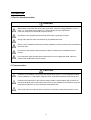
1. Electric shock prevention
DANGER
Wait at least 10 minutes after turning the power OFF, check the voltage between L1-L2-L3
and L11-L12 terminals with a tester, etc., before starting wiring or inspections.
Failure to observe this could lead to electric shocks.
Ground the servo amplifier and servomotor with Class 3 grounding or higher.
Wiring and inspection work must be done by a qualified technician.
Wire the servo amplifier and servomotor after installation. Failure to observe this could lead to
electric shocks.
Do not touch the switches with wet hands. Failure to observe this could lead to electric
shocks.
Do not damage, apply forcible stress, place heavy items or engage the cable. Failure to
observe this could lead to electric shocks.
2. Fire prevention
CAUTION
Install the servo amplifier, servomotor and regenerative resistor on noncombustible material.
Direct installation on combustible material or near combustible materials could lead to fires.
Following the instructions in this manual, always install no-fuse breakers and contactors on
the servo amplifier power input. Select the correct no-fuse breakers and contactors using this
manual as a reference. Incorrect selection could lead to fires.
Shut off the main circuit power at the contactors to emergency stop when an alarm occurs.

III
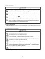
3. Injury prevention
CAUTION
Do not apply a voltage other than that specified in Instruction Manual on each terminal.
Failure to observe this item could lead to ruptures or damage, etc.
Do not mistake the terminal connections. Failure to observe this item could lead to ruptures
or damage, etc.
Do not mistake the polarity(
+
,
–
) . Failure to observe this item could lead to ruptures or
damage, etc.
Do not touch the servo amplifier fins, regenerative resistor or servomotor, etc., while the
power is turned ON or immediately after turning the power OFF. Some parts are heated to
high temperatures, and touching these could lead to burns.
4. Various precuations
Observe the following precautions. Incorrect handling of the unit could lead to faults, injuries and
electric shocks, etc.
(1) Transportation and installation
CAUTION
Correctly transport the product according to its weight.
Do not stack the products above the tolerable number.
Do not hold the cables, axis or detector when transporting the servomotor.
Follow this Instruction Manual and install the unit in a place where the weight can be borne.
Do not get on top of or place heavy objects on the unit.
Always observe the installation directions.
Do not install or run a servo amplifier or servomotor that is damaged or missing parts.
Do not let conductive objects such as screws or metal chips, etc., or combustible materials
such as oil enter the servo amplifier or servomotor.
The servo amplifier and servomotor are precision devices, so do not drop them or apply
strong impacts to them.

IV
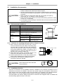
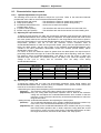
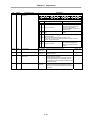
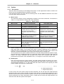
CAUTION
Store and use the units under the following environment conditions.
Conditions
Environment
Servomotor Interface unit
Ambient
temperature
0°C to +40°C
(with no freezing)
0°C to +55°C
(with no freezing)
Ambient humidity
80% RH or less
(with no dew condensation)
90%RH or less
(with no dew condensation)
Storage temperature
–15°C to +65°C
(with no freezing)
–20°C to +65°C
(with no freezing)
Storage humidity
90% RH or less (with no dew condensation)
Atmosphere
Indoors (Where unit is not subject to direct sunlight)
With no corrosive gas, combustible gas, oil mist or dust.
Altitude 1000m or less above sea level
HS-RF
HS-SF
(1kW or less)
X: 9.8m/sec
2
(1G)
Y: Y: 24.5m/sec
2
(2.5G) or less
HS-SF
(2.0kW or
less)
X: 19.6m/sec
2
(2G)
Y: 49m/sec
2
(5G) or
less
Vibration
HS-MF
X: 19.6m/sec
2
(2G)
Y: 19.6m/sec
2
(2G)
or less
5.9m/sec
2
(0.6G) or less
Securely fix the servomotor to the machine. Insufficient fixing could lead to the servomotor
deviating during operation.
Never touch the rotary sections of the servomotor during operations. Install a cover, etc.,
on the shaft.
When coupling to a servomotor shaft end, do not apply an impact by hammering, etc. The
detector could be damaged.
Do not apply a load exceeding the tolerable load onto the servomotor shaft. The shaft
could break.
When storing for a long time, please contact your dealer.

V
(2) Wiring
CAUTION
Correctly and securely perform the wiring. Failure to do so could lead to runaway of the
servomotor.
(3) Trial operation and adjustment
CAUTION
Check and adjust each parameter before starting operation. Failure to do so could lead to
unforeseen operation of the machine.
Do not make remarkable adjustments and changes as the operation could become unstable.
(4) Usage methods
CAUTION
Install an external emergency stop circuit so that the operation can be stopped and power
shut off immediately.
Unqualified persons must not disassemble or repair the unit.
Never make modifications.
Reduce magnetic interference by installing a noise filter. The electronic devices used near
the servo amplifier could be affected by magnetic noise. Install a line noise filter, etc., when
there is an influence from magnetic interference.
Always use the servomotor and servo amplifier with the designated combination.
The servomotor's magnetic brakes are for holding purposes. Do not use them for normal
braking.
There may be cases when holding is not possible due to the magnetic brake's life or the
machine construction (when ball screw and servomotor are coupled via a timing belt, etc.).
Install a stop device to ensure safety on the machine side.

VI
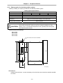
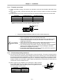
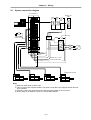
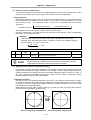
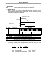
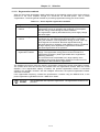
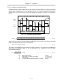
(5) Troubleshooting
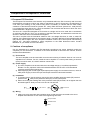
CAUTION
If a hazardous situation is predicted during stop or product trouble, use a servomotor with
magnetic brakes or install an external brake mechanism.
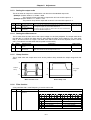
Use a double circuit configuration
that allows the operation circuit for
the magnetic brakes to be operated
even by the external emergency
stop signal.
If an alarm occurs, remove the
cause and secure the safety before
resetting the alarm.
24VDC
EMG
Shut off with CNC brake
control PLC output.
Magnetic
brake
Control in the intelligent
servomotor.
Servomotor
Never go near the machine after restoring the power after a failure, as the machine could
start suddenly.
(Design the machine so that personal safety can be ensured even if the machine starts
suddenly.)
(6) Maintenance, inspection and part replacement
CAUTION
The capacity of the electrolytic capacitor will drop due to deterioration. To prevent secondary
damage due to failures, replacing this part every ten years when used under a normal
environment is recommended. Contact the nearest dealer for repair and replacement of
parts.
(7) Disposal
CAUTION
Treat this unit as general industrial waste.
(8) General precautions
CAUTION
The drawings given in this Specifications and Maintenance Instruction Manual show the
covers and safety partitions, etc., removed to provide a clearer explanation. Always return
the covers or partitions to their respective places before starting operation, and always follow
the instructions given in this manual.

VII
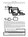
Compliance to European EC Directives
1. European EC Directives
The European EC Directives were issued to unify Standards within the EU Community and to smooth
the distribution of products of which the safety is guaranteed. In the EU Community, the attachment of
a CE mark (CE marking) to the product being sold is mandatory to indicate that the basic safety
conditions of the Machine Directives (issued Jan. 1995), EMC Directives (issued Jan. 1996) and the
Low-voltage Directives (issued Jan. 1997) are satisfied. The machines and devices in which the servo
is assembled are a target for CE marking.
The servo is a component designed not to function as a single unit but to be used with a combination
of machines and devices. Thus, it is not subject to the EMC Directives, and instead the machines and
devices in which the servo is assembled are targeted.
This servo complies with the Standards related to the Low-voltage Directives in order to make CE
marking of the assembled machines and devices easier. The EMC INSTALLATION GUIDELINES (IB
(NA) 67303) which explain the servo amplifier installation method and control panel manufacturing
method, etc., has been prepared to make compliance to the EMC Directives easier. Contact
Mitsubishi or your dealer for more information.
2. Cautions of compliance
Use the standard servo amplifier and EN Standards compliance part (some standard models are
compliant) for the servomotor. In addition to the items described in this instruction manual, observe
the items described below.
(1) Environment
The servo amplifier must be used within an environment having a Pollution Class of 2 or more as
stipulated in the IEC664. For this, install the servo amplifier in a control panel having a structure
(IP54) into which water, oil, carbon and dust cannot enter.
(2) Power supply
1) The servo amplifier must be used with the overvoltage category II conditions stipulated in
IEC664. For this, prepare a reinforced insulated transformer that is IEC or EN Standards
complying at the power input section.
2) When supplying the control signal input/output power supply from an external source, use a 24
VDC power supply of which the input and output have been reinforced insulated.
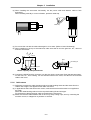
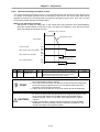
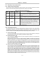
(3) Installation
1) To prevent electric shocks, always connect the servo amplifier protective earth (PE) terminal
(terminal with
mark) to the protective earth (PE) on the control panel.
2) When connecting the earthing wire to the protective earth (PE) terminal, do not tighten the wire
terminals together. Always connect one wire to one terminal.
PE terminal PE terminal
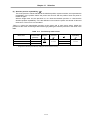
(4) Wiring
1) Always use crimp terminals with insulation tubes so that the wires connected to the servo
amplifier terminal block do not contact the neighboring terminals.
Crimp terminal
Insulation tube
Wire

VIII
(5) Peripheral devices
1) Use a no-fuse breaker and magnetic contactor that comply with the EN/IEC Standards
described in Chapter 7 Peripheral Devices.
2) The wires sizes must follow the conditions below. When using other conditions, follow Table 5
of EN60204 and the Appendix C.
• Ambient temperature: 40°C
• Sheath: PVC (polyvinyl chloride)
• Install on wall or open table tray
(6) Servomotor
Contact Mitsubishi for the outline dimensions, connector signal array and detector cable.
(7) Others
Refer to the EMC INSTALLATION GUIDELINES (IB (NA) 67303) for other EMC Directive
measures related to the servo amplifier.

i
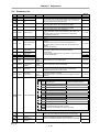
Contents
Chapter 1 Introduction
1-1 Intelligent servomotor outline ............................................................................... 1-2
1-2 Limits and special notes for intelligent servomotor ........................................... 1-2
1-2-2 Precautions for selecting the intelligent servomotor ....................................... 1-2
1-2-2 Precautions for use......................................................................................... 1-2
1-2-3 Miscellaneous ................................................................................................. 1-2
1-3 Inspection at purchase .......................................................................................... 1-3
1-3-1 Explanation of type ......................................................................................... 1-3
Chapter 2 Specifications
2-1 Standard specifications ......................................................................................... 2-2
2-2 Torque characteristics ........................................................................................... 2-3
2-3 Outline dimension drawings ................................................................................. 2-4
2-3-1 HS-MF23 ........................................................................................................ 2-4
2-3-2 HS-RF43/73.................................................................................................... 2-4
2-3-3 HS-SF52/53/102/103 ...................................................................................... 2-5
2-3-4 HS-SF202 ....................................................................................................... 2-5
Chapter 3 Characteristics
3-1 Overload protection characteristics ..................................................................... 3-2
3-2 Magnetic brake characteristics ............................................................................. 3-3
3-2-1 Motor with magnetic brakes............................................................................ 3-3
3-2-2 Magnetic brake characteristics ....................................................................... 3-4
3-2-3 Magnetic brake power supply ......................................................................... 3-4
3-3 Dynamic brake characteristics.............................................................................. 3-5
3-3-1 Deceleration torque ........................................................................................ 3-5
3-3-2 Coasting amount............................................................................................. 3-6
Chapter 4 Peripheral Devices
4-1 Dedicated options .................................................................................................. 4-2
4-1-1 I/F unit............................................................................................................. 4-2
4-1-2 Battery option for absolute position system .................................................... 4-6
4-1-3 Cables and connectors ................................................................................... 4-7
4-1-4 Cable clamp fitting .......................................................................................... 4-11
4-2 Peripheral devices.................................................................................................. 4-12
4-2-1 Selection of wire ............................................................................................. 4-12
4-2-2 Selection of no-fuse breakers ......................................................................... 4-12
4-2-3 Selection of contactor ..................................................................................... 4-13
4-2-4 Circuit protector .............................................................................................. 4-14
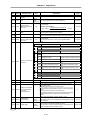
Chapter 5 Installation
5-1 Installation of servomotor ..................................................................................... 5-3
5-1-1 Environmental conditions.............................................................................. 5-3
5-1-2 Cautions for mounting load (prevention of impact on shaft) ........................... 5-3
5-1-3 Installation direction ...................................................................................... 5-3
5-1-4 Tolerable load of axis...................................................................................... 5-4
5-1-5 Oil and waterproofing measures..................................................................... 5-4
5-1-6 Cable stress.................................................................................................... 5-5

ii
5-2 Installation of interface unit................................................................................... 5-6
5-2-1 Environmental conditions................................................................................ 5-6
5-2-2 Installation direction ........................................................................................ 5-6
5-2-3 Prevention of entering of foreign matter ......................................................... 5-6
5-3 Noise measures ...................................................................................................... 5-7
Chapter 6 Wiring
6-1 System connection diagram.................................................................................. 6-3
6-2 Connector................................................................................................................ 6-4
6-2-1 Connector signal layout .................................................................................. 6-4
6-2-2 Signal name.................................................................................................... 6-5
6-3 Connection of power supply ................................................................................. 6-6
6-3-1 Example of connection for controlling magnetic switch (MC)
with MDS-B-CV/CR......................................................................................... 6-6
6-3-2 Example of connection for controlling magnetic switch with
external sequence circuit ................................................................................ 6-8
6-3-3 Wiring of contactors (MC) ............................................................................... 6-8
6-3-4 Surge absorber ............................................................................................... 6-9
6-4 Wiring the motor with brakes ................................................................................ 6-9
6-4-1 Connection example ....................................................................................... 6-9
6-4-2 Manually releasing the magnetic brakes ........................................................ 6-10
6-5 Connection with the NC ......................................................................................... 6-11
6-5-1 Connection system ......................................................................................... 6-11
Chapter 7 Setup
7-1 Setting the initial parameters ................................................................................ 7-2
7-1-1 Servo specification parameters ...................................................................... 7-2
7-1-2 Limitations to electronic gear setting value..................................................... 7-2
7-1-3 Parameters set according to feedrate............................................................. 7-3
7-1-4 Parameters set according to machine load inertia.......................................... 7-3
7-1-5 Standard parameter list according to motor.................................................... 7-4
Chapter 8 Adjustment
8-1 Measurement of adjustment data ......................................................................... 8-2
8-1-1 D/A output specifications ................................................................................ 8-2
8-1-2 Setting the output data.................................................................................... 8-2
8-1-3 Setting the output scale .................................................................................. 8-3
8-1-4 Setting the offset amount................................................................................ 8-3
8-1-5 Clamp function................................................................................................ 8-3
8-1-6 Filter function .................................................................................................. 8-3
8-2 Gain adjustment ..................................................................................................... 8-4
8-2-1 Current loop gain ............................................................................................ 8-4
8-2-2 Speed loop gain.............................................................................................. 8-4
8-2-3 Position loop gain ........................................................................................... 8-6
8-3 Characteristics improvement ................................................................................ 8-8
8-3-1 Optimal adjustment of cycle time.................................................................... 8-8
8-3-2 Vibration suppression measures .................................................................... 8-10
8-3-3 Improving the cutting surface precision .......................................................... 8-12
8-3-4 Improvement of protrusion at quadrant changeover....................................... 8-15
8-3-5 Improvement of overshooting ......................................................................... 8-19

iii
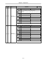
8-3-6 Improvement of characteristics during acceleration/deceleration................... 8-21
8-4 Setting for emergency stop ................................................................................... 8-24
8-4-1 Deceleration control........................................................................................ 8-24
8-4-2 Vertical axis drop prevention control............................................................... 8-26
8-5 Collision detection ................................................................................................ 8-27
8-6 Parameter list.......................................................................................................... 8-30
Chapter 9 Inspections
9-1 Inspections.............................................................................................................. 9-2
9-2 Life parts ................................................................................................................. 9-2
9-3 Replacing the unit .................................................................................................. 9-3
9-3-1 HS-MF23** type.............................................................................................. 9-3
9-3-2 HS-FR43/73, HS-SF52/53/102/103 type ........................................................ 9-3
9-3-3 HS-SF202 type ............................................................................................... 9-4
Chapter 10 Troubleshooting
10-1 Points of caution and confirmation .................................................................... 10-2
10-2 Troubleshooting at start up................................................................................. 10-2
10-3 Protective functions list....................................................................................... 10-3
10-3-1 Alarm .............................................................................................................. 10-3
10-3-2 Warnings list ................................................................................................... 10-7
10-3-3 Alarm and warning deceleration method and reset method ........................... 10-8
Chapter 11 Selection
11-1 Outline ................................................................................................................... 11-2
11-1-1 Servomotor ..................................................................................................... 11-2
11-1-2 Regeneration methods ................................................................................... 11-3
11-2 Selection of servomotor series ........................................................................... 11-4
11-2-1 Motor series characteristics ............................................................................ 11-4
11-2-2 Servomotor precision...................................................................................... 11-4
11-3 Selection of servomotor capacity ....................................................................... 11-6
11-3-1 Load inertia ratio ............................................................................................. 11-6
11-3-2 Short time characteristics ............................................................................... 11-6
11-3-3 Continuous characteristics.............................................................................. 11-7
11-4 Selection of regenerative resistor....................................................................... 11-9
11-4-1 Limits for HS-MF23......................................................................................... 11-9
11-4-2 Approximate calculation of positioning frequency........................................... 11-9
11-4-3 Calculation of regenerative energy ................................................................. 11-9
11-4-4 Calculation of positioning frequency ............................................................... 11-11
11-5 Motor shaft conversion load torque ................................................................... 11-12
11-6 Expressions for load inertia calculation ............................................................ 11-13

1–1
Chapter 1 Introduction
1-1 Intelligent servomotor outline .................................................................... 1-2
1-2 Limits and special notes for intelligent servomotor................................. 1-2
1-2-2 Precautions for selecting the intelligent servomotor............................. 1-2
1-2-2 Precautions for use .............................................................................. 1-2
1-2-3 Miscellaneous ...................................................................................... 1-2
1-3 Inspection at purchase................................................................................ 1-3
1-3-1 Explanation of type .............................................................................. 1-3

Chapter 1 Introduction
1–2
1-1 Intelligent servomotor outline
The Mitsubishi intelligent servomotor is an integrated motor, encoder and amplifier, and has the
following features.
• Space saving
The amplifier does not need to be stored in the power distribution panel, so the machine, power
distribution panel and heat exchanger can be downsized.
• Wire saving
Only one wire is used between the NC and motor. (The signal and 200VAC input are wired with
the same cable.)
• Flexible
As an option axis can be added without changing the power distribution panel, variations can be
easily added to the machine.
• High-speed
As the power distribution panel does not require space, the servo can easily be used for
hydraulic and pneumatic devices.
1-2 Limits and special notes for intelligent servomotor
1-2-1 Precautions for selecting the intelligent servomotor
(1) The intelligent servomotor does not have the regenerative resistor option (the regenerative
resistor capacity cannot be increased.). Make sure that the regenerative energy is less than the
tolerable regenerative capacity. Use the standalone HA/HC Series motor and
MDS-B-V1/V2/SVJ2 Series servo amplifier for applications having a high regenerative energy due
to a high positioning frequency or large load inertia, etc.
(2) The HS-MF23 type does not have a regenerative resistor. There may be limits to the working
rotation speed depending on the load inertia. Avoid using in applications generating continuous
regeneration, such as with a vertical axis.
1-2-2 Precautions for use
(1) IP65 is recommended for the engagement of the HS-RF∗∗/SF∗∗ type connector. Make sure that
water or oil, etc., does not come in contact in the disengaged state.
(2) Connect the HS-MF type relay connector in a relay box having a structure (IP54) that prevents the
entry of water, oil and dust, etc. Fix the enclosed cable to the motor.
(3) A contact that released the brakes when the servo turns ON is built-in. The brakes will not be
released just by inputting the 24V power from an external source. If the brakes need to be
released when assembling the machine, etc., refer to section 6-4. Wiring a motor with brakes.
1-2-3 Miscellaneous
(1) When the motor shaft is turned by hand, it may seem heavier than other servomotors, or may
seem tight. This is caused because of the dynamic brakes in the built-in amplifier, and is not a
fault.

Chapter 1 Introduction
1–3
1-3 Inspection at purchase
Open the package, and read the rating nameplate to confirm that the servo amplifier and servomotor
are as ordered.
1-3-1 Explanation of type
(1) Amplifier + motor integrated type
HS - - S
(2) Part types for separable amplifier and motor
1) Motor/encoder unit type
MDS - B - ISV
2) Motor only type
HS - - s
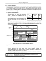
Explanation of rating nameplate
MITSUBISHI ELECTRIC CORPORATION JAPAN
MITSUBISHI
TYPE
HS-SF202EX
INTELLIGENT SERVO
MOTOR HS-SF202
DRIVE UNIT MDS-B-ISV-20EX
RATED INPUT
* 3AC 200-230V 50/60Hz 10.0A
RATED OUTPUT 3AC 11.0A
S/W BND516W000A7 H/W VER. *
SERIAL# XXXXXXXXXXX DATE 00/01
* X X X X X X X X X X X *
Type
Motor section type
Amplifier/encoder section type
and rated input/output
Current version
Serial No.
Motor special symbol (Not provided with standard product)
A
mplifier/encoder special symbol (Cable length, etc.)
Intelligent servomotor
A
mplifier type EX: With amplifier/encoder for NC
Motor Series RF : Medium capacity, low inertia
SF : Medium capacity, medium inertia
MF : Small capacity, ultra-low inertia
: Short-time rated output (W/100) · : Rotation speed (rpm/1000)
103: 1kW·3000r/min 202: 2kW·2000r/min
73: 0.75kW·3000r/min 102: 1kW·2000r/min
53: 0.5kW·3000r/min 52: 0.5kW·2000r/min
43: 0.4kW·3000r/min
23: 200W·3000r/min
Motor option B: Brakes provided
Blank: No brakes
A
mplifier/encoder special symbol (Cable length, etc.)
Intelligent servomotor amplifier/encoder
Short-time rated output (W/100)
20: 2kW 05: 0.5kW
10: 1kW 04: 0.4kW
07: 0.75kW
A
mplifier type EX: With amplifier/encoder for NC
Motor special symbol (Not provided with standard product)
Intelligent servomotor
Motor option B: Brakes provided
Blank: No brakes
: Short-time rated output (W/100) · : Rotation speed (rpm/1000)
103: 1kW·3000r/min 202: 2kW·2000r/min
73: 0.75kW·3000r/min 102: 1kW·2000r/min
53: 0.5kW·3000r/min 52: 0.5kW·2000r/min
43: 0.4kW·3000r/min
Motor Series RF : Medium capacity, low inertia
SF : Medium capacity, medium inertia

2–1
Chapter 2 Specifications
2-1 Standard specifications ............................................................................ 2-2
2-2 Torque characteristics .............................................................................. 2-3
2-3 Outline dimension drawings..................................................................... 2-4
2-3-1 HS-MF23 ........................................................................................... 2-4
2-3-2 HS-RF43/73....................................................................................... 2-4
2-3-3 HS-SF52/53/102/103 ......................................................................... 2-5
2-3-4 HS-SF202 .......................................................................................... 2-5

Chapter 2 Specifications
2–2
2-1 Standard specifications
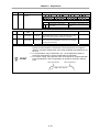
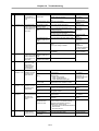
(1) HS-MF, HS-RF Series (Low-inertia, small capacity/low-inertia, medium capacity)
Type HS-MF23 HS-RF43 HS-RF73
Rated output (kW) 0.2/15min 0.4/30min 0.75/30min
Short-time
characteristics
Rated torque (N·m) 0.64 1.27 2.39
Rated output (kW) 0.15 0.32 0.6
Continuous
characteristics
Rated torque (N·m) 0.48 1.02 1.91
Maximum torque (N·m) 1.92 3.18 5.97
Rated rotation speed (r/min) 3000
Maximum rotation speed (r/min) 3000
Moment of inertia J (×10
-4
kg·m
2
) 0.089 0.8 1.5
Detector resolution/method 8,000/absolute value 100,000/absolute value
Voltage/frequency 3-phase 200VAC to 230VAC 50/60Hz (HS-MF23 is single-phase)
Tolerable voltage fluctuation 170 to 253VAC
Tolerable frequency
fluctuation
±5%
Power
supply
Power facility capacity (kVA) 0.5 0.9 1.3
Control method Sine wave PWM control, current control method
Dynamic brakes Built-in
Recommended load moment of inertia
rate
4-fold or less when using cutting axis, 10-fold or less when using peripheral axis
Environment conditions Follows section 3-1-1 Environment conditions
Structure
Fully closed self-cooling: Protective structure IP65 (Excluding MF23 connector. Protection
applies for all connectors when engaged to machine.)
(2) HS-SF Series (medium-inertia, medium-capacity)
Type HS-SF52 HS-SF53 HS-SF102 HS-SF103 HS-SF202
Rated output (kW) 0.5/30min 0.5/30min 1.0/30min 1.0/30min 2.0/30min
Short-time
characteristics
Rated torque (N·m) 2.39 1.59 4.78 3.18 9.55
Rated output (kW) 0.4 0.4 0.75 0.75 1.5
Continuous
characteristics
Rated torque (N·m) 1.91 1.27 3.58 2.39 7.16
Maximum torque (N·m) 11.8 8.82 21.6 16.7 41.7
Rated rotation speed (r/min) 2000 3000 2000 3000 2000
Maximum rotation speed (r/min) 2000 3000 2000 3000 2000
Moment of inertia J (×10
-4
kg·m
2
) 6.6 6.6 13.6 13.6 42.5
Detector resolution/method 100,000/absolute value
Voltage/frequency 3-phase 200VAC to 230VAC 50/60Hz
Tolerable voltage
fluctuation
170 to 253VAC 50/60Hz
Tolerable frequency
fluctuation
±5%
Power
supply
Power facility capacity
(kVA)
1.0 1.0 1.7 1.7 3.5
Control method Sine wave PWM control, current control method
Dynamic brakes Built-in
Recommended load moment of inertia
rate
4-fold or less when using cutting axis, 10-fold or less when using peripheral axis
Environment conditions Follows section 3-1-1 Environment conditions
Structure
Fully closed self-cooling: Protective structure IP65
(Protection applies for connector section when engaged)
Note 1: The rated output and rated rotation speed are the guaranteed values in the 200 to 230VAC 50/60Hz range. The
torque-speed line diagram indicates the characteristics when 200VAC is input. Note that the high-speed characteristics will
drop when the power voltage drops.
Note 2: Make sure that the acceleration/deceleration torque is within 80% of the maximum output torque.
Note 3: Make sure that the continuous effective load torque is within 80% of the motor rated torque.
Note 4: With the HS-MF23, if the recommended load moment of inertia rate is exceeded, an overvoltage alarm may occur because
of the speed and deceleration torque. (Refer to Chapter 11.)
Note 5: Magnetic brakes are prepared for the 0.4KW and larger capacities. The HS-MF23 does not have brake specifications.

Chapter 2 Specifications
2–3
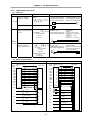
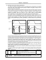
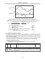
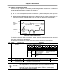
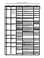
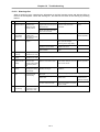
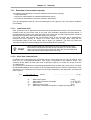
2-2 Torque characteristics
Short-time operation range
Continuous
operation range
Intermittent
operation range
Torque[N・m]
3.0
2.0
1.0
0
0
1000 2000 3000
[HS-MF23]
Torque[N・m]
3.0
2.0
1.0
0
1000 2000
3000
[HS-RF43]
0
4.0
Torque[N・m]
6.0
4.0
2.0
0
1000 2000
3000
[HS-RF73]
0
8.0
Torque[N・m]
10
0
0
1000 2000
[HS-SF52]
Torque[N・m]
0
1000 2000 3000
[HS-SF53]
5
10
0
5
Torque[N・m]
20
0
0 1000
2000
[HS-SF102]
10
Torque[N・m]
0
1000 2000 3000
[HS-SF103]
20
0
10
Torque[N・m]
40
0
0 1000
2000
[HS-SF202]
20
Motor speed
[
r/min
]
Intermittent
operation range
Intermittent
operation range
Intermittent
operation range
Intermittent
operation range
Intermittent
operation range
Intermittent
operation range
Intermittent
operation range
Short-time operation range
Short-time operation range
Short-time operation range
Short-time operation range
Short-time operation range
Short-time operation range
Short-time operation range
Continuous
operation range
Continuous
operation range
Continuous
operation range
Continuous operation
range
Continuous
operation range
Continuous operation
range
Continuous
operation range
Motor speed
[
r/min
]
Motor speed
[
r/min
]
Motor speed
[
r/min
]
Motor speed
[
r/min
]
Motor speed
[
r/min
]
Motor speed
[
r/min
]
Motor speed
[
r/min
]

Chapter 2 Specifications
2–4
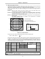
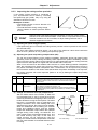
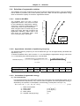
2-3 Outline dimension drawings
2-3-1 HS-MF23
45°
φ
70
Φ
11h6
4
4
2.5
A
Cross-section
A-A
16
30
4
3
7
178
108
18
82
Φ50h7
56.5
101
Φ27
60
±
5
640±30
A
A
With oil seal
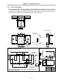
2-3-2 HS-RF43/73
Connector
JL04V-2A28-11PE
LL
93
□
100
25
φ16.000
φ22
28
12
Taper
1/10
18
φ95h7
10
5
0
-0.03
54.3
φ
1
1
5
4-
φ
9
45
゚
L
75
173.5
φ
1
3
5
118
23.3
100
3
A
108.00
A
A
Cross-section
A-A
With oil seal
Changed dimensions
Model L LL
HS-RF43 400W
86
204
HS-RF43B 400W with brakes In planning stages
HS-RF73 750W
104
222
HS-RF73B 750W with brakes In planning stages

Chapter 2 Specifications
2–5
2-3-3 HS-SF52/53/102/103
216
5
0
-0.03
5
4.3
4.25
25
φ16.000
φ22
Taper
1/10
A
130
LL
110h7
18
70
12
3
28 12
58
23.3
□
130
φ
145
φ
165
45°
96
Cross section
A-A
145 L
A
A
Changed dimensions
Model L LL
HS-SF53/52
500W
87
232
HS-SF53/52B
500W with brakes
119
270
HS-SF103/102
1kW
112
257
HS-SF103/102B
1kW with brakes
144
295
2-3-4 HS-SF202
LL
L
75
18
3
79
φ114.3
-0.025
φ35
+0.010
□
176
45°
φ
200
φ
230
264
0
0
70
119
Changed dimensions
Model L LL
HS-SF202
2kW
116
270
HS-SF202B
2kW with brakes In planning stages
Page is loading ...
Page is loading ...
Page is loading ...
Page is loading ...
Page is loading ...
Page is loading ...
Page is loading ...
Page is loading ...
Page is loading ...
Page is loading ...
Page is loading ...
Page is loading ...
Page is loading ...
Page is loading ...
Page is loading ...
Page is loading ...
Page is loading ...
Page is loading ...
Page is loading ...
Page is loading ...
Page is loading ...
Page is loading ...
Page is loading ...
Page is loading ...
Page is loading ...
Page is loading ...
Page is loading ...
Page is loading ...
Page is loading ...
Page is loading ...
Page is loading ...
Page is loading ...
Page is loading ...
Page is loading ...
Page is loading ...
Page is loading ...
Page is loading ...
Page is loading ...
Page is loading ...
Page is loading ...
Page is loading ...
Page is loading ...
Page is loading ...
Page is loading ...
Page is loading ...
Page is loading ...
Page is loading ...
Page is loading ...
Page is loading ...
Page is loading ...
Page is loading ...
Page is loading ...
Page is loading ...
Page is loading ...
Page is loading ...
Page is loading ...
Page is loading ...
Page is loading ...
Page is loading ...
Page is loading ...
Page is loading ...
Page is loading ...
Page is loading ...
Page is loading ...
Page is loading ...
Page is loading ...
Page is loading ...
Page is loading ...
Page is loading ...
Page is loading ...
Page is loading ...
Page is loading ...
Page is loading ...
Page is loading ...
Page is loading ...
Page is loading ...
Page is loading ...
Page is loading ...
Page is loading ...
Page is loading ...
Page is loading ...
Page is loading ...
Page is loading ...
Page is loading ...
Page is loading ...
Page is loading ...
Page is loading ...
Page is loading ...
Page is loading ...
Page is loading ...
Page is loading ...
Page is loading ...
Page is loading ...
Page is loading ...
Page is loading ...
Page is loading ...
Page is loading ...
Page is loading ...
Page is loading ...
Page is loading ...
Page is loading ...
Page is loading ...
Page is loading ...
Page is loading ...
-
 1
1
-
 2
2
-
 3
3
-
 4
4
-
 5
5
-
 6
6
-
 7
7
-
 8
8
-
 9
9
-
 10
10
-
 11
11
-
 12
12
-
 13
13
-
 14
14
-
 15
15
-
 16
16
-
 17
17
-
 18
18
-
 19
19
-
 20
20
-
 21
21
-
 22
22
-
 23
23
-
 24
24
-
 25
25
-
 26
26
-
 27
27
-
 28
28
-
 29
29
-
 30
30
-
 31
31
-
 32
32
-
 33
33
-
 34
34
-
 35
35
-
 36
36
-
 37
37
-
 38
38
-
 39
39
-
 40
40
-
 41
41
-
 42
42
-
 43
43
-
 44
44
-
 45
45
-
 46
46
-
 47
47
-
 48
48
-
 49
49
-
 50
50
-
 51
51
-
 52
52
-
 53
53
-
 54
54
-
 55
55
-
 56
56
-
 57
57
-
 58
58
-
 59
59
-
 60
60
-
 61
61
-
 62
62
-
 63
63
-
 64
64
-
 65
65
-
 66
66
-
 67
67
-
 68
68
-
 69
69
-
 70
70
-
 71
71
-
 72
72
-
 73
73
-
 74
74
-
 75
75
-
 76
76
-
 77
77
-
 78
78
-
 79
79
-
 80
80
-
 81
81
-
 82
82
-
 83
83
-
 84
84
-
 85
85
-
 86
86
-
 87
87
-
 88
88
-
 89
89
-
 90
90
-
 91
91
-
 92
92
-
 93
93
-
 94
94
-
 95
95
-
 96
96
-
 97
97
-
 98
98
-
 99
99
-
 100
100
-
 101
101
-
 102
102
-
 103
103
-
 104
104
-
 105
105
-
 106
106
-
 107
107
-
 108
108
-
 109
109
-
 110
110
-
 111
111
-
 112
112
-
 113
113
-
 114
114
-
 115
115
-
 116
116
-
 117
117
-
 118
118
-
 119
119
-
 120
120
-
 121
121
-
 122
122
-
 123
123
-
 124
124


Mitsubishi HS-7168EB User manual
- Category
- Measuring, testing & control
- Type
- User manual
- This manual is also suitable for
Ask a question and I''ll find the answer in the document
Finding information in a document is now easier with AI
Related papers
Other documents
-
Mitsubishi Electric MR-J2-CT Series Owner's manual
-
Mitsubishi Electric MDS-D2/DH2 Series User manual
-
-
-
-
 poscope POMPG2 Pulse Generator User manual
-
-
-
-
