Page is loading ...

PRINTED IN U.S.A. Part No. 7283536 (Rev. A 5/10/06)
EcoWater Systems
P.O. Box 64420 St.P aul MN 55164 - 9888
OWNERS
MANUAL
How to maintain and operate your
EcoWater multi--purpose filter
SERIES
ETF2100 PF

3
2
Unpacking, Table o f Contents
ECOWATER
S YST E MS
UNPACKING
EcoWater Multi-- Purpose Filters are shipped from
the factory in one master carton consisting of ...
...Mineral tank and valve a ssembly
...Controller cover and timer assembly
...Small parts bags
...Literature kit (includes this manual)
NOTE: Filtering mineral is not included. See
page 21 for ordering information.
Thoroughly check the filter for possible shipping
damage and parts loss. Also inspect and note any
damage to the shipping carton. Notify the trans-
portation company if damage is present. EcoWater
is not responsible for in--transit damages.
Remove and discard (RECYCLE) a ll packing materi-
als. We suggest that you do not open the small parts
bags until you are ready to use them. Filter assem-
bly instructions are on page 5.
TABLE OF CONTENTS
Page
Warranty / Safety Guides 3
Specifications / Dimensions 4
Assembly In stru ctions 5
Planning Installation 6 -- 7
Installation Steps 8 -- 10
Programming Face Plate Timer 11 -- 12
Filter Operation 13 -- 15
General 13
Service / Backwash / Fast Rinse 14
Service Information 16 -- 19
Neutralizing Filter 16
Taste & Odor Filter 16
Troubleshooting 17
Wiring Schematic 19
Repair Parts
20 -- 23

3
3
Warranty, Safety Guides
ECOWATER
S YST E MS
EcoWater Systems LLC
Advantage Warranty
Series ETF 2100 Water System
Congratulations! You have just purchased the highes t quality water c onditioning
product on the market. To regis ter your warranty, complete the enclosed Warranty
Registration Card and mail it within 30 days of purchase.
To whom is this warranty extended?
EcoWater Systems LLC warrants its products to the original owner and guarantees
that the products will be free from defects in materials and workmans hip from the
original date of installation.
How does my warranty work?
If, during the respective warranty period, a part proves, after i nspection by EcoWa-
ter, to be defective, EcoWater will, at its sole option repair or replace that part at
no charge, other than normal shi pping and installation charges.
What is cov ered by the warranty?
EcoWater systems LLC guarantees that,
for the LIFETIME of the original owner, the MINERAL TANK will not rust, corrode,
leak, burst, or i n any other manner fail to perform their proper func tions and that,
for a period of FIVE (5) YEARS after installation, the VALVE BODY will be free of
defects in materials and workmanship and will perform its proper function and that,
for a period of THREE (3) YEARS after installation, the ELECTRONIC FACE-
PLATE will be free of defects in material s and workmanship and will perform its
normal functions and that,
for a period of ONE (1) YEAR after installation, ALL OTHER PARTS will be free of
defects in materials and workmanship and wi ll perform their normal functions .
How do I obtain l ocal service?
Should you need service, your local, independent EcoWater Dealer is only a
phone call away.
PHONE:
If I need a part r eplaced after the factory warranty expires, is that part war-
ranted?
Yes, EcoWater Systems LLC warrants FACTORY REPAIRS as well as al l replace-
ment parts for a period of 90 DAYS.
Are any additional warranties available?
We are pleased to say, YES! EcoWater Sys tems LLC offers an EXTENDED,
PARTS ONLY WARRANTY for the ELECTRONICS portion of your product. This
warranty is cal led the “Perfect Ten” and extends the three year warranty on the
electronic FACEPLATE, WIRING HARNESS, DRIVE MOTOR, TRANSFORMER,
POWER CORD, SENSOR HOUSING, and MICRO SWITCHES to a total of TEN
YEARS from the date of original installation. Shoul d your local dealer not offer this
warranty, you may contac t the factory for additi onal information.*
General Provisions
The above warranties are effective provided the water conditioner is operated at
water pressures not exceeding 125 psi, and at water temperatures not exceeding
120°F; provided further that the water c onditioner is not subject to abuse, misuse,
alteration, neglect, freezing, accident or negli gence; and provided further that the
water conditioner is not damaged as the result of any unusual force of nature such
as, but not limited to, flood, hurricane, tornado or earthquake. EcoWater Systems
LLC, is excused if failure to perform its warranty obligations is the resul t of strikes,
government regulation, materials shortages, or other circumstances beyond its
control.
To obtain warranty service, notice must be given, within thirty (30) days of the dis-
covery of the defect, to your local EcoWater Systems dealer.
*THERE ARE NO WARRANTIES ON THE WATER CONDITIONER BEYOND
THOSE SPECIFICALLY DESCRIBED ABOVE. ALL IMPLIED WARRANTIES, IN-
CLUDING ANY IMPLIED WARRANTY OF MERCHANTABILITY OR OF FITNESS
FOR A PARTICULAR PURPOSE, ARE DISCLAIMED TO THE EXTENT THEY
MIGHT EXTEND BEYOND THE ABOVE PERIODS. THE SOLE OBLIGATIONOF
ECOWATER SYSTEMS LLC UNDER THESE WARRANTIES IS TO REPLACE
OR REPAIR THE COMPONENT OR PART WHICH PROVES TO BE DEFECTIVE
WITHIN THE SPECIFIED TIME PERIOD, AND ECOWATER IS NOT LIABLE FOR
CONSEQUENTIAL OR INCIDENTAL DAMAGES. NO ECOWATER DEALER,
AGENT, REPRESENTATIVE, OR OTHER PERSON IS AUTHORIZED TO EX-
TEND OR EXPAND THE WARRANTIES EXPRESSLY DESCRIBED ABOVE.
Some states do not allow limitations on how long an implied warranty lasts or ex -
clusions or lim itations of i ncidental or consequential damage, so the limitations
and exclusions in this warranty may not apply to you. This warranty gives you spe-
cifi c legal rights, and you may have other rights which vary from state to state. This
warranty applies to consumer--owned i nstallations only.
SAFETY GUIDES
Follow the installation instructions carefully. Failure
to install the filter properly voids the warranty.
Before you begin installation, read this entire manu-
al. Then, obtain all the materials and tools you will
need to make the installation.
Check local plumbing and electrical codes. The
installation must conform to them.
NOTE: Codes in the state of Massachusetts require
installation by a licensed plumber. For installation,
use plumbing code 248--CMR of the Commonwealth
of Massachusetts.
Use only lead--free solder and flux for all
sweat-solder connections, as required by state and
federal codes.
Use care when handling the filter. Do not turn upside
down, drop, or set on sharp protrusions.
Do not locate the filter where freezing temperatures
occur. Do not attempt to filter water over 120°F.
Freezing, or hot water damage voids the warran-
ty.
Avoid installing in direct sunlight. Excessive sun
heat may cause distortion or other damage to non--
metallic parts.
The filter requires a minimum water flow (see specifi-
cations) at the inlet. Maximum allowable inlet wa-
ter pressure is 125 psi. If daytime pressure is over
80 psi, nighttime pressure may exceed the maxi-
mum. Use a pressure reducing valve if necessary.
Adding a pressure reducing valve may reduce the
flow.
This filter works on 24 v olt--60 hz electrical pow-
er only. Be sure to use the included transformer and
plug it into a nominal 120v, 60 cycle household outlet
that is grounded and properly protected by an over
current device such as a circuit breaker or fuse. If
transformer is replaced use only the authorized ser-
vice, class II, 24 volt, 10VA transformer.
This system is not intended to be used for treating
water that is microbiologically unsafe or of unknown
quality without adequate disinfection before or after
the system.
European Directive 2002/96/EC requires all
electrical and electronic equipment to be dis-
posed of according to Waste Electrical and
Electronic Equipment (WEEE) requirements.
This directive or similar laws are in place nationally
and can vary from region to region. Please refer to
your state and local laws for proper disposal of this
equipment.

14”
14”
A
B
3
4
Specifications / Dimensions
ECOWATER
S YST E MS
ETF2100PF10
10” DIA x 47”
RESIN TANK
ETF2100PF12
12” DIA x 54”
RESIN TANK
FILTER TYPE, Mineral ¡
SEDIMENT REMOVAL
Filter Aggregate
limits
factory recommendation
based on water analysis
ACID NEUTRALIZER
Neutralite
water supply
pH limits
6.0to6.8 6.0to6.8
TASTE & ODOR REMOVAL
Activated Carbon
limits
factory recommendation
based on water analysis
AMOUNT MINERAL RECOMMENDED (cu. ft.) 1to1--1/4 2
AMOUNT GRAVEL (lbs.) 17 29
AMOUNT FILTER SAND RECOMMENDED (lbs.) ¡ 10 14 -- 15
SUPPLY WAT ER PRESSURE LIMITS (PSI) 20 -- 125 20 -- 125
SUPPLY WAT ER TEMPERATURE LIMITS (_F) 35 -- 120 35 -- 120
MINIMUM INLET WATER FLOW,
BACKWASH AND FAST RINSE
FLOW TO DRAIN
(gal. per Min.)
5 7
BACKWASH TIME (MINUTES) © 25 25
FAST RINSE TIME (MINUTES) © 5 5
¡ not included with filter © Default times -- cycle length is adjustable
AB
ETF2100PF10 57” 50”
ETF2100PF12 62--1/2” 55--3/4”

3
5
Assembly Instructions
ECOWATER
S YST E MS
FILL THE MINERAL TANK
1. Remove the tank clamps, Figure 1, valve assem-
bly, o--ring seals (3), and the top distributor.
2. Using a funnel, add the specified amount of filter
sand, then the mineral.
NOTE:The filter is factory filled with the correct
amount of gravel. Filter sand, and the desired filter
mineral are not included.
CAUTION: To prevent sand and mineral from enter-
ing the bottom distributor and riser, temporarily plug
with a clean rag.
standpipe
top distributor
resin
tank
valve
assembly
clamp retainer (2)
clamp section (2)
o--ring,
13/16” x 1--1/16”
o--ring,
2--7/8” x 3--1/4”
(thick)
o--ring,
2--3/4’ x 3”
(thin)
standpipe
FIGURE 1
3. Thoroughly clean all sand and mineral from the
tank top opening.
SANITIZING THE FILTER
Care is taken at the factory to keep you water filter
clean and sanitary. Materials used to make the filter
will not infect or contaminate your water supply, and
will not cause bacteria to form or grow . However, dur-
ing shipping, storage, installing and operating,
bacteria could get into the filter. For this reason, sani-
tizing, as follows, is suggested when installing.
Pour about 1 oz. (ETF2100PF10), or 2 oz.
(ETF2100PF12), of the following disinfectant into the
filter.
1. Calcium hypochlorite, available in granular or tablet
form, under trade names such as Perchloron or HTH.
2. Common 5.25% household bleach such as Clorox,
Linco, Bo Peep, White Sail, Eagle, etc.
NOTE -- ACTIVATED CARBON FILTERS: ACTI-
VATED CARBON WILL ABSORB THE SANITIZING
AGENT, EXPENDING SOME CAPACIT Y.
SANITIZING CONTINUED IN STEP 9, PAGE 10,
ANDSTEPIIONPAGE12.
4. Install the top distributor and o-- ring seals (4), ex-
actly a s shown in Figure 1.
5. Lower the valve assembly, onto the mineral tank,
centering over the standpipe, Push downward, to
squeeze the o--rings, and install the clamp sections
and both retainers. BE SURE THE CLAMPS AND
RETAINERS ARE FIRMLY IN PLACE.

3
6
Planning Installation
ECOWATER
S YST E MS
TYPICAL INSTALLATION DRAWINGS
INLET -- OUTLET OPTIONS
1” copper tube
(2 supplied)
1” x 1” sweat
1” x 3/4” sweat
1” sweat x 1”
or 3/4” pipe
thread
floor drain
floor drain
NOTE: Faceplate and support
not shown for clarity of drawing.
Tie or wire valve drain hose in place,
to keep over floor drain.
valve drain hose
valve drain hose
1--1/2”
airgap
120V, 60Hz
outlet
transformer
(supplied)
to timer
to timer
1--1/2”
airgap
INLET
INLET
OUTLET
OUTLET
3-- valve
bypass system
inlet valve
outlet valve
bypass valve
UNFILTERED
WA TER
UNFILTERED
WA TER
FILTERED
WA TER
OUTSIDE
FAUCETS
OUTSIDE
FAUCETS
FIGURE 2
INLET -- OUTLET PLUMBING OPTIONS
1. ALWAYS INSTALL either an EcoWater bypass
valve, #7214383, or a 3 valve bypass system.
2. Use 1”... or, 3/4” (minimum) pipe and fittings.
3. Use sweat copper... or, threaded pipe*... or, PVC
plastic pipe.*
*Sweat soldering is required to adapt to the fittings
(1” male) supplied with the filter, or obtain approved
compression adaptors. The following special fittings
are available from EcoWater. Be sure to comply
with all local plumbing codes.
OPTIONAL INLET/OUTLET FITTINGS
#7104546 PVC Nipple --- Use in place of
included copper inlet and outlet tubes.
#7129211 Adaptor Fitting, 1–1/2” (2) --- Use in
place of included copper inlet and outlet tubes.
#7120259 Elbow --- Extends inlet and/or
outlet in any 90˚ direction.
OTHER REQUIREMENTS
4. A drain is needed for regeneration discharge wa-
ter. A floor drain, close to the filter is preferred. A
laundry tub, standpipe, etc., are other options.
CAUTION: DRAIN WATER EXITS THE HOSE AT A
FAST FLOW RATE, AND AT WATER SYSTEM
PRESSURE. BE SURE THE HOSE IS FASTENED
IN SOME MANNER TO PREVENT “WHIPPING”,
AND SPLASHING TO PREVENT WATER DAMAGE
TO SURROUNDING AREA.
5. A 120v--60Hz, grounded electrical outlet (continu-
ously “live” is need within 10’ of the filter.

3
7
Planning Installation
ECOWATER
S YST E MS
TOOLS YOU MAY NEED
D common screwdriver D pliers
D cross--point screwdriver D tape measure
SOLDERED COPPER THREADED CPVC PLASTIC
D tubing cutter D hacksaw or
pipe cutter
D hacksaw
D propane torch D threading tool D adjustable
wrench
D LEAD--FREE
solder and flux
D pipe joint com-
pound*
D solvent cement*
D emery cloth,
sandpaper or steel
wool
D primer
MATERIALS YOU MAY NEED
H bypass valve, or 3 valves
H pipe and fittings as required
H 5/8” I. D. minimum drain hose, either standard gar-
den hose, or hose onto a barb fitting*
*VALVE DRAIN OPTIONS: Flexible drain hose is
not allowed in all localities (check your codes). For
a rigid valve drain run, plumb according to local
codes. To connect to the valve drain fitting, purchase
an adaptor, garden hose thread x 5/8” (minimum)
tube. Use a hacksaw to cut off barbs from the fitting.
SELECT INSTALLATION LOCATION
Consider all of the following when selecting an
installation location for the filter selected.
S To filter all water in the home, install the filter close
to the water supply inlet. To conserve filtered wa-
ter, outside faucets should remain on raw water.
S If other water conditioning equipment is installed,
locate as shown in Figure 3 .
S A nearby drain is needed to carry away regenera-
tion discharge water. A floor drain is preferred,
with a laundry tub, standpipe, etc., as other op-
tions (check your local codes).
S The filter works on 24 volts only. A transformer is
included (FOR INDOOR USE) to reduce
120V-- 60 Hz house electrical power. Provide an
approved, grounded outlet within 10’ of the filter.
The transformer has an attached 10’ power cable
for connection between the outlet and the timer.
S Position the filter at least 6” from surrounding
walls, or other appliances, to allow access for
servicing.
S If installing the filter in an outside location, be sure
to provide protection from the elements, contami-
nation, vandalism, and sunlight heat. The sun’s
heat can melt plastic parts.
FIGURE 3

3
8
Installation
ECOWATER
S YST E MS
1. INSTALL INLET AND OUTLET FITTINGS
NOTE: All fittings are in the small parts bags.
a. Insert the turbine support, into the valve outlet
port, up to the shoulder.
NOTE: If installing the EcoWater bypass valve, see
separate instructions included with it.
b. Slide a lubricated o--ring onto one of the copper
tubes. Carefully insert the copper tube into the outlet
port (Figure 4) and secure in place with a plastic “C”
clip.
NOTE: For lubrication, use silicone grease ap-
proved for use on potable water supplies.
c. Repeat step b on the inlet side.
2. TURN OFF WATER SUPPLY
a. Close the main water supply valve, near well
pump or water meter.
b. Shut off the electricity or fuel supply to the water
heater.
c. Open high and low faucets to drain all water from
hose pipes.
3. INSTALLING 3--VALVE BYPASS
If installing a 3--valve bypass system, plumb as
needed, using Figure 2 on page 6 as a guide. If
installing sweat copper, be sure to USE LEAD--
FREE SOLDER as required by federal and State
codes. Use pipe joint compound on outside pipe
threads.
4. MOVE FILTER INTO PLACE
Move the filter into the installation position, setting
on a solid. smooth and level surface. If needed,
place the filter on a section of 3/4” plywood. Then
shim under the plywood to level the filter Figure 5.
CAUTION: DO NOT PLACE SHIMS DIRECTLY UN-
DER THE SHROUD. The weight of the tank may
cause the shroud to fracture at the shim.
5. ASSEMBLE INLET AND OUTLET PLUMBING
Measure, cut and loosely assemble pipe and fittings
from the main water pipe (or from bypass valves
installed in step 3 ), to the filter inlet and outlet copper
tubes.
BE SURE UNFILTERED WATER SUPPLY PIPE
GOES TO THE FILTER INLET SIDE. Trace the wa-
ter flow direction to be sure.
VALVE
INLET
o--ring seal (2)
1” copper tube (2)
clip (2)
support
FIGURE 4 FIGURE 5
shroud
3/4” plywood
shim

3
9
Installation
ECOWATER
S YST E MS
6. COLD WATER PIPE GROUNDING
The house cold water pipe (metal only) is often used
as a ground for the house electrical system. The
3-- valve bypass type if installation, shown in Figure
2, will maintain ground continuity. If you use the plas-
tic bypass valve at the filter, continuity is broken. To
restore the ground, install one of the following
grounds.
a. Use the included ground clamp kit to jumper
across the inlet and outlet copper tubes Figure 6a.
b. Install a #4 copper wire across the removed sec-
tion of main water pipe, securely clamping on both
ends (Figure 6b).
7. CONNECT INLET & OUTLET PLUMBING
Complete the inlet and outlet plumbing as applica-
ble.
a. SOLDERED
COPPER
(1) Thoroughly clean and flux all joints.
(2) Remove the inlet and outlet tubes from the valve
(pull plastic “C” clips), and o--rings from the tubes.
DO NOT SOLDER WITH TUBES IN THE VALVE.
SOLDERING HEAT WILL DAMAGE THE VALVE.
(3) Make all solder connections. Be sure to keep fit-
tings fully together, and pipes square and straight.
(4) AFTER PLUMBING HAS COOLED, repeat
steps 1b and 1c.
b. THREADED
PIPE
(1) Apply pipe joint compound to all outside pipe
threads.
(2) Tighten all threaded joints.
(3) If SOLDERING TO INLET AND OUTLET
TUBES, observe steps (1) through (4) above.
c. CPVC PLASTIC
PIPE
(1) Clean, prime and cement all joints (follow instruc-
tions of the plastic pipe and fittings manufacturer).
(2) IF SOLDERING TO INLET AND OUTLET
TUBES, observe preceding steps (1) through (4).
8. INSTALL VALVE DRAIN HOSE
a. Connect a length of 5/8” I.D. (minimum) hose to
the valve drain elbow on the controller Figure 2. The
elbow accepts either a hose onto the barb fitting, or
standard garden hose onto the threads. To use the
threads, cut off the barbs with a hacksaw.
NOTE: Flexible drain hose is not allowed in all locali-
ties. See option on page 7.
b. Run the hose to a floor drain, and as typically
shown in Figure 2, tie or wire the end to a brick or oth-
er heavy object. This will prevent “whipping” during
regenerations. Be sure to provide a 1-- 1/2” minimum
air gap, to prevent possible sewer water backup.
ground wire
clamp (2)
FIGURE 6
FIGURE 7
B
A
3 -- Valve Bypass
OUTLET
VALVE
INLET
VALVE
BYPASS
VALVE
to conditioner
from conditioner
EcoWater
Bypass Valve
D for SERVICE:
-- O p e n the inlet and outlet
valves.
-- C l o s e the bypass valve.
D for BYPASS:
-- C l o s e the inlet and outlet
valves.
-- O p e n the bypass valve.
PUSH IN
for bypass
PULL OUT
for service
ground
clamp

3
10
Installation
ECOWATER
S YST E MS
NOTE: In addition to a floor drain, you can use a
laundry tub or stand pipe as a good drain point for
this hose. Avoid long drain hose runs, or elevating
the hose.
9. PRESSURE TESTING FOR LEAKS
TO PREVENT EXCESSIVE AIR PRESSURE IN
THE FILTER AND PLUMBING SYSTEM, DO THE
FOLLOWING STEPS IN ORDER
a. Open two or more filtered water faucets, both hot
and cold.
b. Referring to Figure 7, turn the bypass valves to
service position.
c. Slowly open the main water supply valve.
d. Close the filtered water faucets after both of the
following occur.
-- water runs smoothly, with no air bubbles
-- you can smell the sanitizing (page 5) bleach odor
at the faucets
e. Check your complete installation for leaks. If re-
work is required, be sure to observe precautions in
step 6.
10. CONNECT ALL LEADWIRES
a. Connect the wire harness to the valve switch Fig-
ure 8. The switch is on the valve, by the large gear.
NOTE: Check to be sure the connector is secure, on
the back of the timer.
b. Attach the male connector, on the valve motor
leadwire, the the matching female connector on the
faceplate timer.
c. Connect the power cable leads to the back of the
timer.
11. CONNECT TO ELECTRICAL POWER
Connect the timer power cable leads to the two ter-
minals on the transformer FIGURE 9. Plug the trans-
former into a continuously “live”, grounded,
120V-- 60Hz house electrical outlet, approved by lo-
cal codes.
12. TO COMPLETE INSTALLATION, DO THE PRO-
GRAMMING STEPS ON PAGES 11 AND 12.
NOTE: SEE WATER HEATER START--UP ON
PAGE .
FIGURE 8
Transformer
24V
position
switch
BACK OF TIMER
120V POWER
SOURCE
valve
motor

3
11
Programming Face Plate Timer
ECOWATER
S YST E MS
FIGURE 9
DOWN keypad
UP keypad
display
SELECT keypad
RECHARGE keypad
VACATION
NOW (HOLD)
I. When the transformer is plugged in, the model
code HPF shows in the face plate display for the first
few seconds. The model code is followed by a test
number (example: J1.0). Then the display will flash
“12:00 PM” and the words “PRESENT TIME”. Set
the present time of day as follows:
A.SetTimeofDay
1. Press the UP or DOWN keypads until the correct
time of day shows, being sure AM or PM shows in the
display.
NOTE: Press and quickly release the keypads to
slowly advance the display. Hold the kaypads down
for fast advance. This procedure applies for all fol-
lowing settings.
2. Press the SELECT keypad once to set the present
time and advance to the next set up screen.
B. Set Days to Recharge
1. This setting is the number of days the filter will go
between recharges. The default setting is 3 days,
with a maximum setting of 99.
2. Press the UP or DOWN keypads until the correct
number of days between recharges is shown in the
display.
3. Press the SELECT keypad once to set the days
to recharge and advance to the next set up screen.
NOTE: See the chart on the following page to deter-
mine the frequency of recharges. Find the number
of people living in the household, and then going
across the chart, find the amount of iron (in parts per
million) that is in the water supply. The number of
days that shows is the number of days the filter
should be set for recharges.

3
12
Programming Face Plate Timer
ECOWATER
S YST E MS
N
u
m
b
e
r
o
f
P
e
o
p
l
e
Iron (parts per million)
N
um
b
er o
f
P
eop
l
e
1--2 3--4 5--7 8--20
1 4 days 3 days 2 days 1 day
2 4 days 3 days 2 days 1 day
3 4 days 3 days 1 day 1 day
4 3 days 2 days 1 day 1 day
5 3 days 2 days 1 day 1 day
6 2 days 1 day 1 day 1 day
7 2 days 1 day 1 day 1 day
NOTE: If the water supply has high turbidity (sand, silt, sediments, etc.) set the filter to regenerate more
often than the table above shows. Carbon and neutralizing filters may only need to backwash once a
week, depending on application.
C. Set Recharge Time
1. Press the UP or DOWN keypads until the correct
recharge time shows, being sure AM or PM shows
in the display. Default for this display is 12:00 AM.
2. Press the SELECT keypad once to set the days
to recharge and advance to the next set up screen.
II. Press and hold the RECHARGE keypad for three
seconds until RECHARGE NOW begins to flash in
the display, starting a backwash. This backwash
flushes “fines” from the new mineral, and purges air
and bleach remaining from the sanitizing procedure.
The filter returns to service in about 30 minutes.
III. RESTART THE WATER HEATER: Turn on the
electric or fuel supply to the water heater, and light
the pilot, if applies.
NOTE: The water heater is filled with unfiltered water
and as hot water is used, it refills with filtered water.
In a few days, hot water will be fully filtered. To have
fully filtered water immediately, wait until the re-
charge (step II above) is over. Then, drain the water
heater until water runs cold.
IV. THE TIMER IS NOW PROGRAMMED AND
INSTALLATION IS COMPLETE.
FEATURES / OPTIONS
RECHARGE NOW -- For an immediate extra back-
wash at any time, use this feature. Press and hold
in the RECHARGE keypad for three seconds until
RECHARGE NOW begins to flash in the display. The
filter backwashes for 25 minutes, followed by a 5
minute fast rinse cycle. Then the filter returns to ser-
vice.
VACATION -- The day you leave on vacation, or oth-
er long absence, press (DO NOT HOLD IN) the RE-
CHARGE keypad. VAC begins to flash in the dis-
play. The timer will keep time, but the filter will not
backwash and waste water.
NOTE: While in the VACATION setting, the filter will
go through a backwash if the RECHARGE NOW
feature is used (see above).
WHEN YOU RETURN, press the RECHARGE key-
pad again to return the filter to service, and the cor-
rect time of day will show in the display. Remember
to do this or the filter will not backwash and you
will soon have unfiltered water.
The default settings for backwash (25 minutes) and
fast rinse (5 minutes) cycles of regeneration are fac-
tory set for maximum performance of the filter. Use
the following procedures to check for correct cycle
times, or to change if desired. However, only trained
technicians should change the time settings.

3
13
Programming Face Plate Timer
ECOWATER
S YST E MS
ADJUSTABLE BACKWASH -- Press and hold the
SELECT button until the display shows “000---- ”,
then press the SELECT button once to advance to
the Backwash time adjust screen.
Using the UP or DOWN buttons, adjust the back-
wash time from 0 minutes to 60 minutes.
ADJUSTABLE FAST RINSE -- Press and hold the
SELECT button until the display shows “000---- ”,
then press the SELECT button twice to advance to
the Fast Rinse time adjust screen.
Using the UP or DOWN buttons, adjust the fast rinse
time from 0 minutes to 60 minutes.
TIMER “POWER--OUTAGE MEMORY” -- If electri-
cal power to the timer is interrupted, the “memory”
built into timer circuitry keeps time settings for 6
hours (minimum) or more. The display is blank and
the filter will not regenerate. When electrical power
comes on, one of two things will happen.
1. The present time of day will show steady, meaning
the timer memory has kept all settings.
2. The display will show a time, but it will be flashing.
The timer memory did not keep the time setting and
it must be reset (page 11). If you do not reset the time
setting, regenerations will most likely be at the wrong
time of day.
NOTE: The flashing display is to remind you to reset
the timer.
NOTE: If the filter was in a backwash when power
was lost, it will now finish the cycle.
Filter Operation
ECOWATER
S YST E MS
GENERAL INFORMATION
...SEDIMENT FILTERS -- A sediment filter removes,
sand, clay, silt, or fine organic matter from water.
You can see sediment in water by holding a sample,
in a clear glass, up to a light. The particles are either
suspended or settled to the bottom of the glass.
“Filter Aggregate” mineral mechanically filters the
sediment particles as water passes through the bed.
This mineral lasts indefinitely when properly main-
tained.
...ACID NEUTRALIZERS -- Acid water (6.0 to 6.8
pH) is corrected with an acid neutralizer filter. Acid
water, although sometimes clear in appearance,
shortens the life of iron pipe, and corrodes copper or
brass pipe and fittings. It causes green or blue
stains on plumbing fixtures and may etch porcelain
enamel over a period of time.
Acid water, as it passes through the filter Neutralite
mineral bed, dissolves some of the mineral. This
raises the pH above 6.8, to neutralize the acid. Be-
cause the mineral does dissolve, the filter eventually
needs refilling. The time between refills varies with
the degree of acidity and how much water is used.
The average life of the bed is about one year.
...TASTE AND ODOR FILTERS -- A taste and odor
filter removes most tastes, odors and certain organic
colors from water. Bad tastes and odors are due to
a variety of causes (chlorine, petroleum, tannins,
etc.). The activated carbon mineral of a taste and
odor filter has a high capacity for absorbing these im-
purities.
The activated carbon bed usually lasts for about one
year. However, high amounts of tastes and odors
and/or excessive water usage may shorten this time.
Activated carbon is nonregenerative and needs re-
placing when exhausted.

3
14
Filter Operation
ECOWATER
S YST E MS
SERVICE, BACKWASH AND FAST RINSE
SERVICE (Figure 10): Unfiltered water enters the
valve inlet port. Internal valve porting routes the wa-
ter down and out the top distributor, into the mineral
tank. The water is filtered as it passes through the
mineral bed, then enters the bottom distributor. Fil-
tered water flows back into the valve and out the
valve outlet, to the house filtered water pipes.
In time, the filter needs cleaning to remove sedi-
ments, dirt, iron, etc., from the mineral bed. This
cleaning is done in two stages, or cycles, called
backwash and fast rinse. It is started automatically
by the timer.
BACKWASH (Figure 11
): The timer starts the valve
motor and moves the valve into backwash position.
Water is routed down and out the bottom distributor,
up through the mineral bed, and out the top distribu-
tor to the drain. The fast flow (controlled by a flow
plug in the d rain fitting) flushes dirt, sediments, iron
deposits, etc. to the drain. The mineral bed is lifted
and expanded for maximum cleaning.
FAST RINSE (Figure 12)
: Valve rotation positions
the inner discs so water flow enters the mineral tank
through the top, and exits at the bottom, to the d rain.
The fast flow of water downward, packs the mineral
bed and prepares it for return to service.
The timer energizes the valve motor again to return
the valve to service
.
WATER FLOW PATHS
FIGURE 10
SERVICE CYCLE
POSITION
SWITCH

3
15
Filter Operation
ECOWATER
S YST E MS
FIGURE 11
BACKWASH CYCLE
FLOW PLUG
POSITION
SWITCH
FIGURE 12
FAST RINSE CYCLE
POSITION
SWITCH

3
16
Service Information
ECOWATER
S YST E MS
NEUTRALIZING FILTER -- CHECKING THE MIN-
ERAL LEVEL IN THE TANK: As explained on page
13, the mineral dissolves in the water to neutralize
the acid. How fast is dissolves depends on how
much water you household uses and the pH o f the
water.
Every few months you should measure the mineral
bed level in the tank. Always add new mineral before
the tank is empty. To measure, do the following.
1. Refer to page 12 and initiate the RECHARGE
NOW feature.
2. When water starts to run from the drain hose, put
the plumbing bypass valve(s) in bypass position,
see Figure 7, page 9, TO DEPRESSURIZE THE
FILTER.
3. Unplug the transformer at the wall outlet.
4. Remove the controller cover.
5. Disconnect the inlet and outlet copper tubes, see
page 8.
6. Remove the valve assembly from the mineral
tank, page 5.
7. Remove the top distributor and four o--ring seals,
page 5.
FIGURE 13
SUGGESTED FREEBOARD
ETF2100PF10 15”
ETF2100PF12 16”
8. Use a yard stick or steel tape measure to find the
distance down to the top of the mineral bed, see Fig-
ure 13. If 15” below the suggested freeboard, add
more neutralite material.
9. Use a funnel to add more mineral, if needed.
10. Flush all mineral from the tank top opening.
Then replace the distributor and four o-- ring seals,
Figure 1, page 5.
11. Do the following steps to return the filter to ser-
vice.
-- step 4, page 5
-- step 1b and 1c, page 8
-- step 8, page 9, if hose was disconnected
-- steps 9 through 12, page 10.
NOTE: After electrical power is applied, see page 13
if the time display is flashing.
-- initiate RECHARGE NOW feature, see page 12.
TASTE AND ODOR FILTER -- REPLACING THE
ACTIVATED CARBON MINERAL BED (SEE PAGE
13): When the filter no longer removes tastes and/or
odors from the water, the activated carbon bed must
be replaced. To replace the bed:
1. Do steps 1 through 7, above left.
2. Carefully lay the filter tank over. Pull the standpipe
and bottom distributor from the mineral bed.
3. Dump the contents of the tank into a suitable con-
tainer.
4. Stand the tank upright and replace the bottom dis-
tributor and standpipe.
5. Add the required amounts of gravel, filter sand,
and activated carbon mineral. See specifications,
page 4.
6. Do steps 10 and 11, above.

3
17
Service Information
ECOWATER
S YST E MS
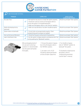
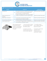
TROUBLESHOOTING
ALWAYS MAKE THESE INITIAL CHECKS FIRST
1. Does the time display show the correct time of
day?
...If display is blank, check power source to the filter.
...If time is flashing, power was off for over two days.
The filter resumes normal operation but back-
washes occur at the wrong time.
2. Plumbing bypass valve(s) must be in SERVICE
position (see figure 7, page 9).
3. The inlet and outlet pipes must connect to the filter
inlet and outlet respectively.
4. Is the transformer plugged into a “live” grounded
wall outlet, and the power cable fastened securely?
5. The valve drain hose must be free of kinks and
sharp bends.
If you do not find the problem after making the initial
checks, do the MANUAL ADVANCE DIAGNOS-
TICS.
MANUAL INITIATED
ELECTRONICS DIAGNOSTIC
1. To enter diagnostics, press and hold the SELECT
keypad until (000-- --) shows in the display.
The letter (P) and dash or dashes indicate position
switch operation. The letter shows if the switch is
closed. A dash shows when the switch is open.
SWITCH
DISPLAYS
VALVE CYCLE STATUS
-- --
valve in service, backwash or fast
rinse position
-- P
valve rotating from one position to
another
Use the RECHARGE keypad to manually advance
the va lve into ea ch cycle and check correct switch
operation.
While in this diagnostic screen, the following infor-
mation is available and may be beneficial tor various
reasons. This information is retained by the comput-
er from the first time electrical power is applied to the
face plate.
...Press the UP keypad to display the number of
days this face plate has had electrical power ap-
plied.
...Press the DOWN keypad to display the number of
regenerations initiated by this face plate since the
model code number was entered.
2. Press the SELECT keypad and hold for 3 seconds
until the model code appears in the display.
NOTE: For correct filter operation, the model code
must be HPF.
To reset the code, press the UP or DOWN keypads
until the correct model code shows in the display.
3. Press the SELECT keypad to return the present
time display. If the code was changed, make ALL the
timer settings, page 11 and 12.
NOTE: If the face plate is left in a diagnostic display (or a flashing display when setting times or days
to recharge), preset time automatically returns if a button is not pressed within 4 minutes.

3
18
Service Information
ECOWATER
S YST E MS
MANUAL ADVANCE DIAGNOSTIC
Use the following procedures to advance the filter
valve through the regeneration cycles to check op-
eration.
Remove the top cover to observe cam and switch
operation during valve rotation.
DISPLAY MUST SHOW TIME AND DAY
1. Press and hold the RECHARGE keypad for 3 sec-
onds until RECHARGE NOW flashes in the display
and the filter moves into the ba ckwash cycle.
...If the motor does not run, check the motor and all
wiring connections.
Look for a fast flow of water from the drain hose (see
specifications).
...An obstructed flow indicates a plugged top distrib-
utor, backwash flow plug, or drain hose.*
NOTE: Be sure household water pressure (well sys-
tem) is maintained at a minimum of 20 psi. Adjust the
pump switch upward, if needed.
2. Press the RECHARGE keypad to move the filter
into fast rinse. Again, look for a drain flow rate about
the same as backwash.
3. To return the filter to service, press the RE-
CHARGE keypad once.
OTHER SERVICE
UNFILTERED WATER BYPASS (unfiltered water
“bleeds” into filtered water supply.
1. Missing or defective o--ring(s) at resin tank to
valve connection (see Figure 1, page 5).
2. Defective rotor disc, seal or wave washer (see
pages and ).
WATER LEAKS FROM DRAIN HOSE (during ser-
vice)
1. Defective rotor disc, seal, or wave washer.
2. Defective o-- ring on disc shaft.
AUTOMATIC ELECTRONIC DIAGNOSTICS
The face plate has a self diagnostic function for the
electrical systems (except input power). The face
plate monitors the electronic components and cir-
cuits for correct operation. If a malfunction occurs,
an error code appears in the face plate display.
POSSIBLE DEFECT
CODE MOST LIKELY ³-- -- -- -- -- -- -- -- -- -- -- -- -- -- -- -- -- -- -- -- -- -- -- -- -- -- -- -- -- -- -- -- -- -- -- -- -- -- -- -- -- -- -- -- -- -- -- ³ LEAST LIKELY
Err 01 Err 02
Err 03 Err 04
wiring harness or connection to position switch / switch / valve defect causing high torque / motor
inoperative
Err 05 faceplate
PROCEDURE FOR REMOVING ERROR CODE FROM FACEPLATE: 1. Unplug transformer-------- 2. Correct defect-------- 3.
Plug in transformer-------- 4. Wait for 12 minutes. The error code will return if the defect was not corrected. Press and hold the RECHARGE
keypad for 3 seconds as an alternate way to clear an error code.

3
19
Service Information
ECOWATER
S YST E MS
M
24V
WIRING SCHEMATIC
BACK OF TIMER
NC
NO
POSITION
SWITCH
24VAC
TRANSFORMER

3
20
Repair Parts
ECOWATER
S YST E MS
17
18
3
1
2
8
7
9
10
11
12
13
14
15
16
5
6
4
/