Page is loading ...

Page 1
02/13
*2P0213*
507067-01
*P507067-01*
E 2013 Lennox Industries Inc.
Dallas, Texas, USA
AIR FLOW
UPFLOW
AIR FLOW
AIR FLOW
HORIZONTAL RIGHT
HORIZONTAL LEFT
INSTALLATION
INSTRUCTIONS
EL296UHE
ELITE
®
SERIES GAS FURNACE
UPFLOW / HORIZONTAL AIR DISCHARGE
507067-01
02/2013
Supersedes 01/2012
THIS MANUAL MUST BE LEFT WITH THE
HOMEOWNER FOR FUTURE REFERENCE
This is a safety alert symbol and should never be ignored.
When you see this symbol on labels or in manuals, be alert
to the potential for personal injury or death.
WARNING
Improper installation, adjustment, alteration, service
or maintenance can cause property damage, person
al injury or loss of life. Installation and service must
be performed by a licensed professional installer (or
equivalent), service agency or the gas supplier.
CAUTION
As with any mechanical equipment, personal injury
can result from contact with sharp sheet metal
edges. Be careful when you handle this equipment.
Table of Contents
Unit Dimensions 2................................
EL296UHE Gas Furnace 3.........................
Shipping and Packing List 3........................
Safety Information 3...............................
Use of Furnace as a Construction Heater 4...........
General 5........................................
Combustion, Dilution, Ventilation Air 5...............
Setting Equipment 8...............................
Filters 13..........................................
Duct System 13....................................
Pipe and Fittings Specifications 13...................
Joint Cementing Procedure 15.......................
Venting Practices 15................................
Gas Piping 38.....................................
Electrical 40.......................................
Integrated Control 43...............................
Unit Start Up 49....................................
Gas Pressure Measurement 50......................
Proper Combustion 51..............................
High Altitude 51....................................
Other Unit Adjustments 53..........................
Sequence of Operation 53..........................
Repair Parts List 54................................
Service 55........................................
Start-Up and Performance Checklist 56...............
Litho U.S.A.

Page 2
EL296UHE Unit Dimensions - inches (mm)
1−1/
2
(38)
9/16
(14
)
AIR FLOW
mm in.
6−9/16 (167)
Left
9 (229)
Right
23
(584)
(19)
3/4
(19)
1
Bottom Return
Air Opening
GAS PIPING INLET
(Either Side)
Side Return
Air Opening
(Either Side)
1
Bottom Return
Air Opening
EXHAUST AIR
OUTLET
ELECTRICAL
INLET
(Either Side)
SUPPLY AIR
OPENING
FRONT VIEW SIDE VIEW
TOP VIEW
A
B
9/16 (14)
C
3/4
27−3/4
(705)
19−7/16
(494)
23−1/2
(597)
6−1/2 (165)
(Either Side)
33
(838)
3−1/4
(83)
1−15/16 (49)
14
(356)
12−5/8 (321)
(Either Side)
2
OPTIONAL
SIDE RETURN
AIR FILTER KIT
(Either Side)
16
(406)
14−3/4
(375)
2
OPTIONAL
SIDE RETURN
AIR FILTER KIT
(Either Side)
ABCD
Model No.
in. mm in. mm in. mm
17−1/2 446 16−3/8 416 16 406 7−5/8 194
21 533 19−7/8 505 19−1/2 495 9−3/8 238
EL296UH110XE60C
24−1/2 622 23−3/8 594 23 584 11−1/8 283
5/8
(16)
1
3−1/4
(83)
23−3/4
(603)
25
(635)
D
1−1/2 (38)
Front Panel
COMBUSTION
AIR INTAKE
2 (51)
(Either Side)
1−7/8 (48)
CONDENSATE
TRAP CONNECTION
(Either Side)
2
Optional External Side Return Air Filter Kit is not for use
with the optional Return Air Base.
1. Single side return air with transition, to accommodate
20 x 25 x 1 in. (508 x 635 x 25 mm) cleanable air
filter. Required to maintain proper air velocity.
2. Single side return air with optional Return Air Base
3. Bottom return air.
4. Return air from both sides.
5. Bottom and
one side return air.
See Blower Performance
tables for additional information.
1
NOTE − 60C and 60D size units that require air
volumes 1800 cfm or over (850 L/s) must have
one of the following
EL296UH045XE36B
EL296UH070XE36B
EL296UH090XE48C
EL296UH135XE60D

Page 3
EL296UHE Gas Furnace
The EL296UHE Category IV gas furnace is shipped ready
for installation in the upflow or horizontal position. The fur
nace is shipped with the bottom panel in place. The bot
tom panel must be removed if the unit is to be installed in
horizontal or upflow applications with bottom return air.
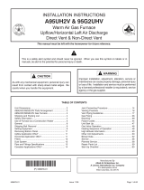
The EL296UHE can be installed as either a Direct Vent
or a Non-Direct Vent gas central furnace.
The furnace is equipped for installation in natural gas ap
plications. A conversion kit (ordered separately) is re
quired for use in propane/LP gas applications.
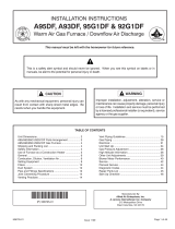
NOTE - In Direct Vent installations, combustion air is taken
from outdoors and flue gases are discharged outdoors. In
Non-Direct Vent installations, combustion air is taken from
indoors or ventilated attic or crawlspace and flue gases are
discharged outdoors. See figures 1 and 2 for applications in
volving roof termination.
FIGURE 1
DIRECT VENT INSTALLATION NON-DIRECT VENT
INSTALLATION
EXHAUST
OUTLET
COMBUSTION
AIR INTAKE OUTSIDE
OF HOUSE
COMBUSTION
AIR INTAKE
INSIDE
OF HOUSE
EXHAUST OUTLET
FIGURE 2
NON-DIRECT VENT
INSTALLATION
NON-DIRECT VENT
INSTALLATION
COMBUSTION
AIR INTAKE INSIDE
VENTILATED
CRAWL SPACE
COMBUSTION
AIR INTAKE INSIDE
VENTILATED
ATTIC SPACE
EXHAUST
OUTLET
EXHAUST
OUTLET
Shipping and Packing List
Package 1 of 1 contains
1 - Assembled EL296UHE unit
1 - Bag assembly containing the following:
1 - Snap bushing
1 - Snap plug
1 - Wire tie
1 - Condensate trap
1 - Condensate trap cap
1 - Condensate trap clamp
1 - 2” diameter debris screen
1 - 3/4” Threaded street elbow
Check equipment for shipping damage. If you find any
damage, immediately contact the last carrier.
The following items may also be ordered separately:
1 - Thermostat
1 - LP/Propane changeover kit
1 - Return air base kit
1 - Horizontal suspension kit
1 - High altitude pressure switch
Safety Information
CAUTION
As with any mechanical equipment, personal injury
can result from contact with sharp sheet metal
edges. Be careful when you handle this equipment.
DANGER
Danger of explosion.
There are circumstances in which odorant used with
LP/propane gas can lose its scent. In case of a leak,
LP/propane gas will settle close to the floor and may
be difficult to smell. An LP/propane leak detector
should be installed in all LP applications.
Use only the type of gas approved for use with this furnace.
Refer to unit nameplate.
EL296UHE units are CSA International certified to ANSI
Z21.47 and CSA 2.3 standards.
Building Codes
In the USA, installation of gas furnaces must conform with lo
cal building codes. In the absence of local codes, units must
be installed according to the current National Fuel Gas Code
(ANSI‐Z223.1/NFPA 54). The National Fuel Gas Code is
available from the following address:
American National Standards Institute, Inc.
11 West 42nd Street
New York, NY 10036
In Canada, installation must conform with current National
Standard of Canada CSA‐B149 Natural Gas and Propane
Installation Codes, local plumbing or waste water codes
and other applicable local codes.

Page 4
In order to ensure proper unit operation in non-direct vent
applications, combustion and ventilation air supply must be
provided according to the current National Fuel Gas Code
or CSA‐B149 standard.
Installation Locations
This furnace is CSA International certified for installation
clearances to combustible material as listed on the unit
nameplate and in the table in figure 12. Accessibility and ser
vice clearances must take precedence over fire protection
clearances.
NOTE - For installation on combustible floors, the furnace
shall not be installed directly on carpeting, tile, or other
combustible material other than wood flooring.
For installation in a residential garage, the furnace must
be installed so that the burner(s) and the ignition source
are located no less than 18 inches (457 mm) above the
floor. The furnace must be located or protected to avoid
physical damage by vehicles. When a furnace is installed
in a public garage, hangar, or other building that has a haz
ardous atmosphere, the furnace must be installed accord
ing to recommended good practice requirements and cur
rent National Fuel Gas Code or CSA B149 standards.
NOTE - Furnace must be adjusted to obtain a temperature
rise within the range specified on the unit nameplate. Failure
to do so may cause erratic limit operation and premature heat
exchanger failure.
This EL296UHE furnace must be installed so that its
electrical components are protected from water.
Installed in Combination with a Cooling Coil
When this furnace is used with cooling coils (figure 3), it shall
be installed in parallel with, or on the upstream side of, cool
ing coils to avoid condensation in the heating compartment.
With a parallel flow arrangement, a damper (or other means
to control the flow of air) must adequately prevent chilled air
from entering the furnace. If the damper is manually oper
ated, it must be equipped to prevent operation of either the
heating or the cooling unit, unless it is in the full HEAT or
COOL setting.
When installed, this furnace must be electrically grounded
according to local codes. In addition, in the United States,
installation must conform with the current National Electric
Code, ANSI/NFPA No. 70. The National Electric Code
(ANSI/NFPA No. 70) is available from the following ad
dress:
National Fire Protection Association
1 Battery March Park
Quincy, MA 02269
In Canada, all electrical wiring and grounding for the unit
must be installed according to the current regulations of the
Canadian Electrical Code Part I (CSA Standard C22.1)
and/or local codes.
FIGURE 3
Gas Unit
Heating Unit Installed Upstream of Cooling Coil
Gas Unit
Dampers
(open during heating operation only)
Dampers
(open during cooling operation only)
Heating Unit Installed Parallel to Air Handler Unit
Air Handler Unit
Cooling Coil
AIR FLOWAIR FLOW
AIR FLOW AIR FLOW
NOTE - This furnace is designed for a minimum continu
ous return air temperature of 60°F (16°C) or an intermit
tent operation down to 55°F (13°C) dry bulb for cases
where a night setback thermostat is used. Return air tem
perature must not exceed 85°F (29°C) dry bulb.
The EL296UHE furnace may be installed in alcoves, clos
ets, attics, basements, garages, crawl spaces and utility
rooms in the upflow or horizontal position.
This furnace design has not been CSA certified for installa
tion in mobile homes, recreational vehicles, or outdoors.
Use of Furnace as Construction Heater
Lennox does not recommend the use of EL296UHE units
as a construction heater during any phase of construction.
Very low return air temperatures, harmful vapors and op
eration of the unit with clogged or misplaced filters will dam
age the unit.
EL296UHE units may be used for heating of buildings or
structures under construction, if the following conditions
are met:
D The vent system must be permanently installed per
these installation instructions.
D A room thermostat must control the furnace. The use of
fixed jumpers that will provide continuous heating is not
allowed.
D The return air duct must be provided and sealed to the
furnace.
D Return air temperature range between 60°F (16°C) and
80°F (27°C) must be maintained.
D Air filters must be installed in the system and must be
maintained during construction.
D Air filters must be replaced upon construction comple
tion.

Page 5
D The input rate and temperature rise must be set per the
furnace rating plate.
D One hundred percent (100%) outdoor air must be pro
vided for combustion air requirements during construc
tion. Temporary ducting may supply outdoor air to the
furnace. Do not connect duct directly to the furnace.
Size the temporary duct following these instructions in
section for Combustion, Dilution and Ventilation Air in a
confined space with air from outside.
D The furnace heat exchanger, components, duct system,
air filters and evaporator coils must be thoroughly
cleaned following final construction clean-up.
D All furnace operating conditions (including ignition, in
put rate, temperature rise and venting) must be verified
according to these installation instructions.
General
These instructions are intended as a general guide and do
not supersede local codes in any way. Consult authorities
having jurisdiction before installation.
In addition to the requirements outlined previously, the fol
lowing general recommendations must be considered
when installing an EL296UHE furnace:
• Place the furnace as close to the center of the air dis
tribution system as possible. The furnace should also be
located close to the vent termination point.
• When the furnace is installed in non-direct vent applica
tions, do not install the furnace where drafts might blow
directly into it. This could cause improper combustion
and unsafe operation.
• When the furnace is installed in non-direct vent applica
tions, do not block the furnace combustion air opening
with clothing, boxes, doors, etc. Air is needed for proper
combustion and safe unit operation.
• When the furnace is installed in an attic or other insu
lated space, keep insulation away from the furnace.
• When the furnace is installed in an unconditioned
space, consider provisions required to prevent freezing
of condensate drain system.
• The “A” coil drain pan is high quality engineering poly
mer with a maximum service temperature of 500° F.
However, adequate space must be provided between
the drain pan and the furnace heat exchanger. At least
2” space is required for sectionalized heat exchanger
and and 4” for drum-type or oil-fired furnace exchanger.
Closer spacing may damage the drain pan and cause
leaking.
CAUTION
EL296UHE unit should not be installed in areas nor
mally subject to freezing temperatures.
WARNING
The State of California has determined that this prod
uct may contain or produce a chemical or chemicals,
in very low doses, which may cause serious illness
or death. It may also cause cancer, birth defects or
reproductive harm.
WARNING
Insufficient combustion air can cause headaches,
nausea, dizziness or asphyxiation. It will also cause
excess water in the heat exchanger resulting in rust
ing and premature heat exchanger failure. Excessive
exposure to contaminated combustion air will result
in safety and performance related problems. Avoid
exposure to the following substances in the com
bustion air supply:
Permanent wave solutions
Chlorinated waxes and cleaners
Chlorine base swimming pool chemicals
Water softening chemicals
De-icing salts or chemicals
Carbon tetrachloride
Halogen type refrigerants
Cleaning solvents (such as perchloroethylene)
Printing inks, paint removers, varnishes, etc.
Hydrochloric acid
Cements and glues
Antistatic fabric softeners for clothes dryers
Masonry acid washing materials
Combustion, Dilution & Ventilation Air
If the EL296UHE is installed as a Non-Direct Vent Fur
nace, follow the guidelines in this section.
NOTE - In Non-Direct Vent installations, combustion air
is taken from indoors or ventilated attic or crawlspace
and flue gases are discharged out-doors.
In the past, there was no problem in bringing in sufficient
outdoor air for combustion. Infiltration provided all the air
that was needed. In today's homes, tight construction
practices make it necessary to bring in air from outside
for combustion. Take into account that exhaust fans, ap
pliance vents, chimneys, and fireplaces force additional
air that could be used for combustion out of the house.
Unless outside air is brought into the house for combus
tion, negative pressure (outside pressure is greater than
inside pressure) will build to the point that a downdraft
can occur in the furnace vent pipe or chimney. As a result,
combustion gases enter the living space creating a po
tentially dangerous situation.
In the absence of local codes concerning air for combus-
tion and ventilation, use the guidelines and procedures in
this section to install EL296UHE furnaces to ensure effi
cient and safe operation. You must consider combustion
air needs and requirements for exhaust vents and gas

Page 6
piping. A portion of this information has been reprinted
with permission from the National Fuel Gas Code (ANSI-
Z223.1/NFPA 54). This reprinted material is not the com
plete and official position of the ANSI on the referenced
subject, which is represented only by the standard in its
entirety.
In Canada, refer to the CSA B149 installation codes.
CAUTION
Do not install the furnace in a corrosive or contami
nated atmosphere. Meet all combustion and ventila
tion air requirements, as well as all local codes.
All gas‐fired appliances require air for the combustion pro
cess. If sufficient combustion air is not available, the fur
nace or other appliance will operate inefficiently and un
safely. Enough air must be provided to meet the needs of all
fuel-burning appliances and appliances such as exhaust
fans which force air out of the house. When fireplaces, ex
haust fans, or clothes dryers are used at the same time as
the furnace, much more air is required to ensure proper
combustion and to prevent a downdraft. Insufficient air
causes incomplete combustion which can result in carbon
monoxide.
In addition to providing combustion air, fresh outdoor air di
lutes contaminants in the indoor air. These contaminants
may include bleaches, adhesives, detergents, solvents
and other contaminants which can corrode furnace compo
nents.
The requirements for providing air for combustion and ven
tilation depend largely on whether the furnace is installed in
an unconfined or a confined space.
Unconfined Space
An unconfined space is an area such as a basement or
large equipment room with a volume greater than 50 cubic
feet (1.42 m
3
) per 1,000 Btu (.29 kW) per hour of the com
bined input rating of all appliances installed in that space.
This space also includes adjacent rooms which are not
separated by a door. Though an area may appear to be un
confined, it might be necessary to bring in outdoor air for
combustion if the structure does not provide enough air by
infiltration. If the furnace is located in a building of tight
construction with weather stripping and caulking around
the windows and doors, follow the procedures in the Air
from Outside section.
Confined Space
A confined space is an area with a volume less than 50 cubic
feet (1.42 m
3
) per 1,000 Btu (.29 kW) per hour of the com-
bined input rating of all appliances installed in that space. This
definition includes furnace closets or small equipment rooms.
When the furnace is installed so that supply ducts carry air
circulated by the furnace to areas outside the space con
taining the furnace, the return air must be handled by ducts
which are sealed to the furnace casing and which terminate
outside the space containing the furnace. This is especially
important when the furnace is mounted on a platform in a
confined space such as a closet or small equipment room.
Even a small leak around the base of the unit at the platform
or at the return air duct connection can cause a potentially
dangerous negative pressure condition. Air for combustion
and ventilation can be brought into the confined space ei
ther from inside the building or from outside.
Air from Inside
If the confined space that houses the furnace adjoins a
space categorized as unconfined, air can be brought in by
providing two permanent openings between the two
spaces. Each opening must have a minimum free area of 1
square inch (645 mm
2
) per 1,000 Btu (.29 kW) per hour of
total input rating of all gas-fired equipment in the confined
space. Each opening must be at least 100 square inches
(64516 mm
2
). One opening shall be within 12 inches (305
mm) of the top of the enclosure and one opening within 12
inches (305 mm) of the bottom. See figure 4.
FIGURE 4
EQUIPMENT IN CONFINED SPACE - ALL AIR FROM INSIDE
OPENINGS
(To Adjacent
Unconfined
Space)
NOTE - Each opening shall have a free area of at least one square inch
per 1,000 Btu (645mm
2
per .29kW) per hour of the total input rating of
all equipment in the enclosure, but not less than 100 square inches
(64516mm.
2).
ROOF TERMINATED
EXHAUST PIPE
SIDE WALL
TERMINATED
EXHAUST PIPE
(ALTERNATE
LOCATION)
EL296UH
E

Page 7
Air from Outside
If air from outside is brought in for combustion and ventila
tion, the confined space shall be provided with two perma
nent openings. One opening shall be within 12” (305mm)
of the top of the enclosure and one within 12” (305mm) of
the bottom. These openings must communicate directly
or by ducts with the outdoors or spaces (crawl or attic) that
freely communicate with the outdoors or indirectly
through vertical ducts. Each opening shall have a mini
mum free area of 1 square inch per 4,000 Btu (645mm
2
per 1.17kW) per hour of total input rating of all equipment
in the enclosure (figures 5 and 8). When communicating
with the outdoors through horizontal ducts, each opening
shall have a minimum free area of 1 square inch per 2,000
Btu (645mm
2
per .59kW) per total input rating of all equip
ment in the enclosure (See figure 9). It is also permissible
to bring in air for combustion from a ventilated attic (figure
6) or ventilated crawl space (figure 7).
FIGURE 5
EQUIPMENT IN CONFINED SPACE - ALL AIR FROM OUTSIDE
(Inlet Air from Crawl Space and Outlet Air to Outside)
NOTE-The inlet and outlet air openings shall each have a free area
of at least one square inch per 4,000 Btu (645mm
2
per 1.17kW) per
hour of the total input rating of all equipment in the enclosure.
OUTLET
AIR
INLET
AIR
VENTILATION
LOUVERS
(For unheated
crawl space)
FURNACE
ROOF TERMINATED
EXHAUST PIPE
VENTILATION LOUVERS
(Each end of attic)
SIDE WALL
TERMINATED
EXHAUST PIPE
(ALTERNATE
LOCATION)
FIGURE 6
EQUIPMENT IN CONFINED SPACE
(Inlet Air from Ventilated Attic and Outlet Air to Outside)
NOTE-The inlet and outlet air openings shall each have a free area
of at least one square inch per 4,000 Btu (645mm
2
per 1.17kW) per
hour of the total input rating of all equipment in the enclosure.
Ventilation Louvers
Inlet Air
(Minimum
12 in.(305mm) Abov
e
attic floor)
Roof Terminated
Exhaust Pipe
Furnace
*Intake Debris
Screen
(Provided)
* See table 6 for maximum vent lengths
FIGURE 7
NOTE-The inlet and outlet air openings shall each have a free area
of at least one square inch per 4,000 Btu (645mm
2
per 1.17kW) per
hour of the total input rating of all equipment in the enclosure.
EQUIPMENT IN CONFINED SPACE
(Inlet Air from Ventilated Crawlspace and Outlet Air to Outside)
Roof Terminated
Exhaust Pipe
Furnace
Ventilation
Louvers
(Crawl space)
*Intake Debris Screen Provided)
Inlet Air
(Minimum
12 in.(305mm)
Above crawl
space floor)
Coupling or
3 in. to 2 in.
Transition
(Field Provided)
* See table 6 for maximum vent lengths
When ducts are used, they shall be of the same cross-sec
tional area as the free area of the openings to which they
connect. The minimum dimension of rectangular air ducts
shall be no less than 3 inches (75 mm). In calculating free
area, the blocking effect of louvers, grilles, or screens
must be considered. If the design and free area of protec
tive covering is not known for calculating the size opening
required, it may be assumed that wood louvers will have
20 to 25 percent free area and metal louvers and grilles
will have 60 to 75 percent free area. Louvers and grilles
must be fixed in the open position or interlocked with the
equipment so that they are opened automatically during
equipment operation.
FIGURE 8
EQUIPMENT IN CONFINED SPACE - ALL AIR FROM OUTSIDE
(All Air Through Ventilated Attic)
NOTE-The inlet and outlet air openings shall each have a free area of
at least one square inch per 4,000 Btu (645mm
2
per 1.17kW) per hour
of the total input rating of all equipment in the enclosure.
OUTLET
AIR
VENTILATION LOUVERS
(Each end of attic)
INLET AIR
(Ends 12” above
bottom)
ROOF TERMINATED
EXHAUST PIPE
SIDE WALL
TERMINATED
EXHAUST PIPE
(ALTERNATE
LOCATION)
FURNACE

Page 8
FIGURE 9
EQUIPMENT IN CONFINED SPACE -
ALL AIR FROM OUTSIDE
OUTLET AIR
INLET AIR
NOTE-Each air duct opening shall have a free area of at least one
square inch per 2,000 Btu (645mm
2
per .59kW) per hour of the total
input rating of all equipment in the enclosure. If the equipment room
is located against an outside wall and the air openings communi
cate directly with the outdoors, each opening shall have a free area
of at least 1 square inch per 4,000 Btu (645mm
2
per 1.17kW) per
hour of the total input rating of all other equipment in the enclosure.
ROOF TERMINATED
EXHAUST PIPE
SIDE WALL
TERMINATED
EXHAUST PIPE
(ALTERNATE
LOCATION)
FURNACE
Shipping Bolt Removal
Units with 1/2 hp blower motor are equipped with three flex
ible legs and one rigid leg. The rigid leg is equipped with a
shipping bolt and a flat white plastic washer (rather than the
rubber mounting grommet used with a flexible mounting
leg). See figure 10. The bolt and washer must be re
moved before the furnace is placed into operation. Af
ter the bolt and washer have been removed, the rigid leg
will not touch the blower housing.
FIGURE 10
RIGID LEG
(Remove shipping bolt
and washer)
EL296 Furnaces with
1/2 HP Blower Motor
Installation - Setting Equipment
WARNING
Do not connect the return air duct to the back of the
furnace. Doing so will adversely affect the operation
of the safety control devices, which could result in
personal injury or death.
WARNING
Blower access panel must be securely in place when
blower and burners are operating. Gas fumes, which
could contain carbon monoxide, can be drawn into
living space resulting in personal injury or death.
Upflow Applications
The EL296UHE gas furnace can be installed as shipped
in the upflow position. Refer to figure 12 for clearances.
Select a location that allows for the required clearances
that are listed on the unit nameplate. Also consider gas
supply connections, electrical supply, vent connection,
condensate trap and drain connections, and installation
and service clearances [24 inches (610 mm) at unit
front]. The unit must be level from side to side. The unit
may be positioned from level to ½” toward the front. See
figure 11.
Allow for clearances to combustible materials as indicated
on the unit nameplate.

Page 9
FIGURE 11
SETTING EQUIPMENT
UPFLOW APPLICATION
HORIZONTAL APPLICATION
FRONT VIEW
SIDE VIEW
FRONT VIEW
END VIEW
UNIT
FRONT
AIR FLOW
UNIT
FRONT
1/2”
max.
1/2”
max.
AIR FLOW
AIR FLOW
SIDE VIEW
UNIT
FRONT
Unit must be level side-to-side. Unit may be positioned from level to 1/2” toward the front to aid in draining.

Page 10
WARNING
Improper installation of the furnace can result in per
sonal injury or death. Combustion and flue products
must never be allowed to enter the return air system
or air in the living space. Use sheet metal screws and
joint tape to seal return air system to furnace.
In platform installations with furnace return, the fur
nace should be sealed airtight to the return air ple
num. A door must never be used as a portion of the
return air duct system. The base must provide a
stable support and an airtight seal to the furnace. Al
low absolutely no sagging, cracks, gaps, etc.
For no reason should return and supply air duct sys
tems ever be connected to or from other heating de
vices such as a fireplace or stove, etc. Fire, explo
sion, carbon monoxide poisoning, personal injury
and/or property damage could result.
Installation Clearances
Top
Bottom (Floor)
Left Side
Right Side
Top/Plenum 1 in. (25 mm)
*Front 0
Back 0
Sides 0†
Vent 0
Floor 0‡
*Front clearance in alcove installation must be 24 in. (610 mm).
Maintain a minimum of 24 in. (610 mm) for front service access.
†Allow proper clearances to accommodate condensate trap.
‡For installations on a combustible floor, do not install the furnace
directly on carpeting, tile or other combustible materials other
than wood flooring.
FIGURE 12
Return Air Guidelines
Return air can be brought in through the bottom or either
side of the furnace installed in an upflow application. If the
furnace is installed on a platform with bottom return, make
an airtight seal between the bottom of the furnace and the
platform to ensure that the furnace operates properly and
safely. The furnace is equipped with a removable bottom
panel to facilitate installation.
Markings are provided on both sides of the furnace cabinet
for installations that require side return air. Cut the furnace
cabinet at the maximum dimensions shown on page 2.
Refer to Product Specifications for additional information.
EL296UHE applications which include side return air
and a condensate trap installed on the same side of the
cabinet (trap can be installed remotely within 5 ft.) re
quire either a return air base or field-fabricated transi
tion to accommodate an optional IAQ accessory taller
than 14.5”. See figure 13.
Side Return Air
(with transition and filter)
FIGURE 13
Return
Air
Plenum
Transition
20” X 25” X 1”
(508mmX635mmX25mm)
Air Filter
1−1/2”

Page 11
FIGURE 14
Optional Return Air Base
(Upflow Applications Only)
NOTE- Optional side return air filter kits are not for use with return air base.
1
Both the unit return air opening and the base return air opening must be covered by a single plenum or IAQ cabinet.
Minimum unit side return air opening dimensions for units requiring 1800 cfm of air and over (W x H): 23 x 11 in. (584 x 279 mm).
The opening can be cut as needed to accommodate plenum or IAQ cabinet while maintaining dimensions shown.
Side return air openings must be cut in the field. There are cutting guides stenciled on the cabinet for the side return air
opening. The size of the opening must not extend beyond the markings on the furnace cabinet.
2
To minimize pressure drop, the largest opening height possible (up to 14 inches) is preferred.
FRONT VIEW
1
Unit side return air
Opening
SIDE VIEW
3−1/4
(83)
1
23 (584)
Overall
(Maximum)
(584)
23
3/4
(19)
1
22−7/16
(570)
Overall
(Maximum
)
SIDE RETURN
AIR OPENINGS
(Either Side)
5−5/8
(143)
1
Minimum
11 (279)
2
Maximum
14 (356)
(683)
26−7/8
7−1/4
(184)
FURNACE
FRONT
AIR FLOW
IF BASE
IS USED
WITHOUT
IAQ CABINET,
A SINGLE
RETURN AIR
PLENUM
MUST
COVER BOTH
UNIT AND
RETURN
AIR BASE
OPENINGS
INDOOR AIR
QUALITY
CABINET
(PCO, Filter
Cabinet, etc.)
AIR BASE
OPTIONAL
RETURN
17−1/2 (446) B Width (50W98)
21 (533) C Width (50W99)
24−1/2 (622) D Width (51W00)
Removing the Bottom Panel
FIGURE 15
Screw
Bottom Panel
Bottom Cap
Removing the Bottom Panel
Remove the two screws that secure the bottom cap to the
furnace. Pivot the bottom cap down to release the bottom
panel. Once the bottom panel has been removed, reinstall
the bottom cap. See figure 15.
Horizontal Applications
FIGURE 16
Front
Back
WARNING
Do not install the furnace on its front or back.
See figure 16.

Page 12
The EL296UHE furnace can be installed in horizontal ap
plications with either right- or left-hand air discharge.
Refer to figure 17 for clearances in horizontal applications.
Horizontal Application
Installation Clearances
Left End Right End
Right-Hand Discharge
Left-Hand Discharge
Top
Bottom (Floor)**
Bottom (Floor)**
Left End Right End
Air
Flow
Air
Flow
Air
Flow
Air
Flow
Top 0
Front* 0
Back 0
Ends 0
Vent 0
Floor 0‡
*Front clearance in alcove installation must be 24 in. (610 mm).
Maintain a minimum of 24 in. (610 mm) for front service access.
**An 8” service clearance must be maintained below the unit to
provide for servicing of the condensate trap.
‡For installations on a combustible floor, do not install the furnace
directly on carpeting, tile or other combustible materials other
than wood flooring.
FIGURE 17
Suspended Installation of Horizontal Unit
This furnace may be installed in either an attic or a crawl
space. Either suspend the furnace from roof rafters or
floor joists, as shown in figure 18, or install the furnace on
a platform, as shown in figure 19. A horizontal suspension
kit (51W10) may be ordered from Lennox or use equiva
lent.
NOTE - Heavy-gauge sheet metal straps may be used to
suspend the unit from roof rafters or ceiling joists. When
straps are used to suspend the unit in this way, support
must be provided for both the ends. The straps must not
interfere with the plenum or exhaust piping installation.
Cooling coils and supply and return air plenums must
be supported separately.
FIGURE 18
HORIZONTAL SUSPENSION KIT
Bracket
(typical)
Metal Strap
(typical)
Air
Flow
Internal Brace
(provided with kit)
NOTE - When the furnace is installed on a platform or with
the horizontal suspension kit in a crawlspace, it must be
elevated enough to avoid water damage, accommodate
drain trap and to allow the evaporator coil to drain.
Platform Installation of Horizontal Unit
1 - Select location for unit keeping in mind service and
other necessary clearances. See figure 17.
2 - Construct a raised wooden frame and cover frame
with a plywood sheet. If unit is installed above finished
space, install an an auxiliary drain pan under unit. Set
unit in drain pan as shown in figure 19. Leave 8 inches
for service clearance below unit for condensate trap.
3 - Provide a service platform in front of unit. When instal
ling the unit in a crawl space, a proper support platform
may be created using concrete blocks.
4 - Route auxiliary drain line so that water draining from
this outlet will be easily noticed by the homeowner.
5 - If necessary, run the condensate line into a conden
sate pump to meet drain line slope requirements. The
pump must be rated for use with condensing furnaces.
Protect the condensate discharge line from the pump
to the outside to avoid freezing.
6 - Continue with exhaust, condensate and intake piping
installation according to instructions.

Page 13
*Gas connector may be
used for Canadian
installation if accept
able by local authority
having jurisdiction.
FIGURE 19
*GAS CONNECTION
RAISED
PLATFORM
SERVICE PLATFORM
INTAKE PIPE
EXHAUST PIPE
Return Air -- Horizontal Applications
Return air may be brought in only through the end of a fur
nace installed in the horizontal position. The furnace is
equipped with a removable bottom panel to facilitate
installation. See figure 15.
Filters
This unit is not equipped with a filter or rack. A field-pro
vided high velocity rated filter is required for the unit to oper
ate properly. Table 1 lists recommended filter sizes.
A filter must be in place whenever the unit is operating.
IMPORTANT
If a highefficiency filter is being installed as part of
this system to ensure better indoor air quality, the fil
ter must be properly sized. Highefficiency filters
have a higher static pressure drop than standardef
ficiency glass/foam filters. If the pressure drop is too
great, system capacity and performance may be re
duced. The pressure drop may also cause the limit to
trip more frequently during the winter and the indoor
coil to freeze in the summer, resulting in an increase
in the number of service calls.
Before using any filter with this system, check the
specifications provided by the filter manufacturer
against the data given in the appropriate Lennox
Product Specifications bulletin. Additional informa
tion is provided in Service and Application Note
ACC002 (August 2000).
TABLE 1
Furnace
Cabinet Width
Filter Size
Side Return Bottom Return
17-1/2” 16 X 25 X 1 (1) 16 X 25 X 1 (1)
21” 16 X 25 X 1 (1) 20 X 25 X 1 (1)
24-1/2” 16 X 25 X 1 (2) 24 X 25 X 1 (1)
Duct System
Use industry‐approved standards to size and install the
supply and return air duct system. Refer to ACCA Manual
D. This will result in a quiet and low‐static system that has
uniform air distribution.
NOTE - This furnace is not certified for operation in heating
mode (indoor blower operating at selected heating speed)
with an external static pressure which exceeds 0.8 inches
w.c. Operation at these conditions may result in improper
limit operation.
Supply Air Plenum
If the furnace is installed without a cooling coil, a removable
access panel should be installed in the supply air duct. The
access panel should be large enough to permit inspection
of the heat exchanger. The furnace access panel must al
ways be in place when the furnace is operating and it must
not allow leaks.
Return Air Plenum
NOTE - Return air must not be drawn from a room
where this furnace, or any other gas-fueled appliance
(i.e., water heater), or carbon monoxide-producing de
vice (i.e., wood fireplace) is installed.
When return air is drawn from a room, a negative pres
sure is created in the room. If a gas appliance is operating
in a room with negative pressure, the flue products can
be pulled back down the vent pipe and into the room. This
reverse flow of the flue gas may result in incomplete com
bustion and the formation of carbon monoxide gas. This
raw gas or toxic fumes might then be distributed through
out the house by the furnace duct system.
Return air can be brought in through the bottom or either
side of the furnace (return air brought into either side of fur
nace allowed only in upflow applications). If a furnace with
bottom return air is installed on a platform, make an airtight
seal between the bottom of the furnace and the platform to
ensure that the unit operates properly and safely. Use fiber
glass sealing strips, caulking, or equivalent sealing method
between the plenum and the furnace cabinet to ensure a
tight seal. If a filter is installed, size the return air duct to fit
the filter frame.
Pipe & Fittings Specifications
All pipe, fittings, primer and solvent cement must conform
with American National Standard Institute and the Ameri
can Society for Testing and Materials (ANSI/ASTM) stan
dards. The solvent shall be free flowing and contain no
lumps, undissolved particles or any foreign matter that ad
versely affects the joint strength or chemical resistance of
the cement. The cement shall show no gelation, stratifica
tion, or separation that cannot be removed by stirring. Re
fer to the table 2 below for approved piping and fitting ma
terials.

Page 14
CAUTION
Solvent cements for plastic pipe are flammable liq
uids and should be kept away from all sources of
ignition. Do not use excessive amounts of solvent
cement when making joints. Good ventilation should
be maintained to reduce fire hazard and to minimize
breathing of solvent vapors. Avoid contact of ce
ment with skin and eyes.
TABLE 2
PIPING AND FITTINGS SPECIFICATIONS
Schedule 40 PVC (Pipe) D1785
Schedule 40 PVC (Cellular Core Pipe) F891
Schedule 40 PVC (Fittings) D2466
Schedule 40 CPVC (Pipe) F441
Schedule 40 CPVC (Fittings) F438
SDR-21 PVC or SDR-26 PVC (Pipe) D2241
SDR-21 CPVC or SDR-26 CPVC (Pipe) F442
Schedule 40 ABS Cellular Core DWV (Pipe) F628
Schedule 40 ABS (Pipe) D1527
Schedule 40 ABS (Fittings) D2468
ABS-DWV (Drain Waste & Vent)
(Pipe & Fittings)
D2661
PVC-DWV (Drain Waste & Vent)
Pipe & Fittings)
D2665
PRIMER & SOLVENT CEMENT
ASTM
SPECIFICATION
PVC & CPVC Primer F656
PVC Solvent Cement D2564
CPVC Solvent Cement F493
ABS Solvent Cement D2235
PVC/CPVC/ABS All Purpose Cement For
Fittings & Pipe of the same material
D2564, D2235, F493
ABS to PVC or CPVC Transition Solvent
Cement
D3138
CANADA PIPE & FITTING & SOLVENT
CEMENT
MARKING
PVC & CPVC Pipe and Fittings
ULCS636
PVC & CPVC Solvent Cement
ABS to PVC or CPVC Transition Cement
IMPORTANT
EL296UHE exhaust and intake connections are
made of PVC. Use PVC primer and solvent cement
when using PVC vent pipe. When using ABS vent
pipe, use transitional solvent cement to make con
nections to the PVC fittings in the unit.
Use PVC primer and solvent cement or ABS solvent cement
meeting ASTM specifications, refer to Table 2. As an alter
nate, use all purpose cement, to bond ABS, PVC, or CPVC
pipe when using fittings and pipe made of the same materi
als. Use transition solvent cement when bonding ABS to ei
ther PVC or CPVC.
Low temperature solvent cement is recommended during
installation in cooler weather. Metal or plastic strapping may
be used for vent pipe hangers. Uniformly apply a liberal coat
of PVC primer for PVC or use a clean dry cloth for ABS to
clean inside socket surface of fitting and male end of pipe to
depth of fitting socket.
Canadian Applications Only - Pipe, fittings, primer
and solvent cement used to vent (exhaust) this ap
pliance must be certified to ULC S636 and supplied by a
single manufacturer as part of an approved vent (ex
haust) system. In addition, the first three feet of vent
pipe from the furnace flue collar must be accessible for
inspection.
Joint Cementing Procedure
All cementing of joints should be done according to the
specifications outlined in ASTM D 2855.
DANGER
DANGER OF EXPLOSION!
Fumes from PVC glue may ignite during system
check. Allow fumes to dissipate for at least 5 minutes
before placing unit into operation.
1 - Measure and cut vent pipe to desired length.
2 - Debur and chamfer end of pipe, removing any ridges
or rough edges. If end is not chamfered, edge of pipe
may remove cement from fitting socket and result in a
leaking joint.
NOTE - Check the inside of vent pipe thoroughly for
any obstruction that may alter furnace operation.
3 - Clean and dry surfaces to be joined.
4 - Test fit joint and mark depth of fitting on outside of pipe.
5 - Uniformly apply a liberal coat of PVC primer for PVC or
use a clean dry cloth for ABS to clean inside socket
surface of fitting and male end of pipe to depth of fitting
socket.
NOTE - Time is critical at this stage. Do not allow prim
er to dry before applying cement.
6 - Promptly apply solvent cement to end of pipe and in
side socket surface of fitting. Cement should be ap
plied lightly but uniformly to inside of socket. Take
care to keep excess cement out of socket. Apply sec
ond coat to end of pipe.
7 - Immediately after applying last coat of cement to pipe,
and while both inside socket surface and end of pipe
are wet with cement, forcefully insert end of pipe into
socket until it bottoms out. Turn PVC pipe 1/4 turn dur
ing assembly (but not after pipe is fully inserted) to dis
tribute cement evenly. DO NOT turn ABS or cellular
core pipe.
NOTE - Assembly should be completed within 20 sec
onds after last application of cement. Hammer blows
should not be used when inserting pipe.

Page 15
8 - After assembly, wipe excess cement from pipe at end
of fitting socket. A properly made joint will show a
bead around its entire perimeter. Any gaps may indi
cate an improper assembly due to insufficient sol
vent.
9 - Handle joints carefully until completely set.
Venting Practices
FIGURE 20
* See table 2 for allowable pipe.
Piping Suspension Guidelines
NOTE - Isolate piping at the point where it exits the outside wall or
roof in order to prevent transmission of vibration to the structure.
SCHEDULE 40
PVC - 5'
all other pipe* - 3'
Wall
inside outside
24” maximum
3/4” minimum
Wall Thickness Guidelines
insulation
(if required)
NOTE - All horizontal runs of exhaust pipe must slope back to
ward unit a minimum of 1/4” (6mm) drop for each 12” (305mm).
1 - In areas where piping penetrates joists or interior
walls, hole must be large enough to allow clearance on
all sides of pipe through center of hole using a hanger.
2 - When furnace is installed in a residence where unit is
shut down for an extended period of time, such as a
vacation home, make provisions for draining conden
sate collection trap and lines.
Removal of the Furnace from Common Vent
In the event that an existing furnace is removed from a
venting system commonly run with separate gas ap
pliances, the venting system is likely to be too large to
properly vent the remaining attached appliances.
Conduct the following test while each appliance is operat
ing and the other appliances (which are not operating) re
main connected to the common venting system. If the
venting system has been installed improperly, you must
correct the system as indicated in the general venting re
quirements section.
WARNING
CARBON MONOXIDE POISONING HAZARD
Failure to follow the steps outlined below for each
appliance connected to the venting system being
placed into operation could result in carbon mon
oxide poisoning or death.
The following steps shall be followed for each ap
pliance connected to the venting system being
placed into operation, while all other appliances
connected to the venting system are not in
operation:
1 - Seal any unused openings in the common venting sys
tem.
2 - Inspect the venting system for proper size and horizontal
pitch. Determine that there is no blockage, restriction,
leakage, corrosion, or other deficiencies which could
cause an unsafe condition.
3 - Close all building doors and windows and all doors be
tween the space in which the appliances remaining
connected to the common venting system are located
and other spaces of the building. Turn on clothes dry
ers and any appliances not connected to the common
venting system. Turn on any exhaust fans, such as
range hoods and bathroom exhausts, so they will oper
ate at maximum speed. Do not operate a summer ex
haust fan. Close fireplace dampers.
4 - Follow the lighting instructions. Turn on the appliance
that is being inspected. Adjust the thermostat so that
the appliance operates continuously.
5 - After the main burner has operated for 5 minutes, test
for leaks of flue gases at the draft hood relief opening.
Use the flame of a match or candle.
6 - After determining that each appliance connected to the
common venting system is venting properly, (step 3)
return all doors, widows, exhaust fans, fireplace damp
ers, and any other gas-burning appliances to their pre
vious mode of operation.
7 - If a venting problem is found during any of the preced
ing tests, the common venting system must be modi
fied to correct the problem.

Page 16
Resize the common venting system to the minimum
vent pipe size determined by using the appropriate
tables in Appendix G. (These are in the current stan
dards of the National Fuel Gas Code ANSI Z223.1.
CHIMNEY
OR GAS
VENT
(Check sizing
for water
heater only)
FURNACE
(Replaced
by EL296)
WATER
HEATER
OPENINGS
(To Adjacent
Room)
If an EL296UHE furnace replaces a furnace which
was commonly vented with another gas appliance,
the size of the existing vent pipe for that gas ap
pliance must be checked. Without the heat of the
original furnace flue products, the existing vent pipe
is probably oversized for the single water heater or
other appliance. The vent should be checked for
proper draw with the remaining appliance.
FIGURE 21
REPLACING FURNACE THAT
WAS PART OF A COMMON
VENT SYSTEM
Exhaust Piping (Figures 22, 24 and 25)
Route piping to outside of structure. Continue with installa
tion following instructions given in piping termination sec
tion.
CAUTION
Do not discharge exhaust into an existing stack or
stack that also serves another gas appliance. If verti
cal discharge through an existing unused stack is re
quired, insert PVC pipe inside the stack until the end
is even with the top or outlet end of the metal stack.
CAUTION
The exhaust vent pipe operates under positive pres
sure and must be completely sealed to prevent leak
age of combustion products into the living space.
Vent Piping Guidelines
The EL296UHE can be installed as either a Non-Direct
Vent or a Direct Vent gas central furnace.
NOTE - In Non‐Direct Vent installations, combustion air is
taken from indoors or ventilated attic or crawlspace and flue
gases are discharged outdoors. In Direct Vent installations,
combustion air is taken from outdoors and flue gases are
discharged outdoors.
Intake and exhaust pipe sizing -- Size pipe according to
tables 3 and
5. Count all elbows inside and outside the
home. Table 3 lists the minimum vent pipe lengths per
mitted. Table 5 lists the maximum pipe lengths permitted.
Regardless of the diameter of pipe used, the standard roof
and wall terminations described in section Exhaust Piping
Terminations should be used. Exhaust vent termination
pipe is sized to optimize the velocity of the exhaust gas as
it exits the termination. Refer to table 8.
In some applications which permit the use of several differ
ent sizes of vent pipe, a combination vent pipe may be
used. Contact Lennox' Application Department for assis
tance in sizing vent pipe in these applications.
NOTE - The exhaust collar on all models is sized to ac
commodate 2” Schedule 40 vent pipe. In horizontal ap
plications, any transition to exhaust pipe larger than 2”
must be made in vertical runs of the pipe. Therefore a 2”
elbow must be added before the pipe is transitioned to
any size larger than 2”. This elbow must be added to the
elbow count used to determine acceptable vent lengths.
Contact the Application Department for more information
concerning sizing of vent systems which include multiple
pipe sizes.
FIGURE 22
Horizontal Installation Offset Requirements
NOTE - Exhaust pipe MUST be glued to furnace exhaust fittings.
NOTE - All horizontal runs of exhaust pipe must slope back to
ward unit. A minimum of 1/4” (6mm) drop for each 12” (305mm)
of horizontal run is mandatory for drainage.
NOTE - Exhaust piping should be checked carefully to make
sure there are no sags or low spots.
Exhaust Pipe
Horizontal
Gas Furnace
12” Min.
12” Max.
TABLE 3
MINIMUM VENT PIPE LENGTHS
EL296UHE
MODEL
MIN. VENT LENGTH*
045, 070, 090, 110, 135
15 ft. or
5 ft. plus 2 elbows or
10 ft. plus 1 elbow
*Any approved termination may be added to the minimum length listed.

Page 17
Use the following steps to correctly size vent pipe diameter.
FIGURE 23
Piping Size Process
1
2
3
4
5
6
Which style termination
being used?
Standard or concentric?
See table 4.
Which needs
most elbows?
Intake or
exhaust?
How many elbows?
Count all elbows inside
and outside house.
Desired pipe size?
2”, 2-1/2”, 3”
Use table 5 or 6 to find
max intake or exhaust pipe
length. Includes all vent
pipe and elbows inside
and outside the house.
What is the altitude of
the furnace installation?
7
What is the
furnace capacity?
045, 070, 090,
110 or 135?
IMPORTANT
Do not use screens or perforated metal in exhaust or
intake terminations. Doing so will cause freeze-ups
and may block the terminations.

Page 18
TABLE 4
OUTDOOR TERMINATION USAGE
Input Size
Vent
Pipe
Dia. in.
STANDARD CONCENTRIC
FlushMount
Kit
Wall Kit Wall Ring Kit
Field
Fabricated
1-1/2 inch 2 inch 3 inch
2 inch 3 inch 2 inch
51W11 (US)
51W12 (CA)
22G44 (US)
4
30G28 (CA)
44J40 (US)
4
81J20 (CA)
15F74
71M80
(US)
4
44W92
(CA)
69M29
(US)
4
44W92
(CA)
60L46 (US)
4
44W93 (CA)
045
2
3
YES YES
1
YES
1
YES
5
YES
2
YES
2-1/2
3
YES YES
1
YES
1
YES
5
YES
2
YES
3
3
YES YES
1
YES
1
YES
5
YES
2
YES
070
2
3
YES YES
1
YES
1
YES
5
YES
2
YES
2-1/2
3
YES YES
1
YES
1
YES
5
YES
2
YES
3
3
YES YES
1
YES
1
YES
5
YES
2
YES
090
2
3
YES YES YES
5
YES YES YES
2-1/2
3
YES YES YES
5
YES YES YES
3
3
YES YES YES
5
YES YES YES
110
2 YES YES YES
5
YES YES YES
2-1/2 YES YES
5
YES YES YES
3 YES YES
5
YES YES YES
135 3 YES
YES
5
YES YES
NOTE - Standard Terminations do not include any vent pipe or elbows external to the structure. Any vent pipe or elbows external to the structure must be included in total vent length
calculations. See vent length tables.
1
Requires field-provided outdoor 1-1/2” exhaust accelerator.
2
Concentric kits 71M80 and 44W92 include 1-1/2” outdoor accelerator, when used with 045 and 070 input models.
3
Flush mount kit 51W11 and 51W12 includes 1-1/2 in. outdoor exhaust accelerator, required when used with 045, 070 and 090 input models.
4
Termination kits 30G28, 44W92, 44W93 and 81J20 are certified to ULC S636 for use in Canada only.
5
See table 8 for vent accelerator requirements.

Page 19
TABLE 5
Maximum Allowable Intake or Exhaust Vent Length in Feet
NOTE - Size intake and exhaust pipe length separately. Values in table are for Intake OR Exhaust, not combined total. Both Intake and Exhaust must be same pipe
size.
NOTE - Additional vent pipe and elbows used to terminate the vent pipe outside the structure must be included in the total vent length calculation.
Standard Termination at Elevation 0 - 4500 ft
Number Of
90° Elbows
Used
2” Pipe 2-1/2” Pipe 3” Pipe
Model Model Model
045 070 090 110 135 045 070 090 110 135 045 070 090 110 135
1 81 66 44 24
n/a
115 115 93 58
n/a
138 137 118 118 114
2 76 61 39 19 110 110 88 53 133 132 113 113 109
3 71 56 34 14 105 105 83 48 128 127 108 108 104
4 66 51 29
n/a
100 100 78 43 123 122 103 103 99
5 61 46 24 95 95 73 38 118 117 98 98 94
6 56 41 19 90 90 68 33 113 112 93 93 89
7 51 36 14 85 85 63 28 108 107 88 88 84
8 46 31
n/a
80 80 58 23 103 102 83 83 79
9 41 26 75 75 53 18 98 97 78 78 74
10 36 21 70 70 48 13 93 92 73 73 69
Standard Termination Elevation 4500 - 10,000 ft
Number Of
90° Elbows
Used
2” Pipe 2-1/2” Pipe 3” Pipe
Model Model Model
045 070 090 110 135 045 070 090 110 135 045 070 090 110 135
1 81 66 44
n/a n/a
115 115 93 58
n/a
138 137 118 118 114
2 76 61 39 110 110 88 53 133 132 113 113 109
3 71 56 34 105 105 83 48 128 127 108 108 104
4 66 51 29 100 100 78 43 123 122 103 103 99
5 61 46 24 95 95 73 38 118 117 98 98 94
6 56 41 19 90 90 68 33 113 112 93 93 89
7 51 36 14 85 85 63 28 108 107 88 88 84
8 46 31
n/a
80 80 58 23 103 102 83 83 79
9 41 26 75 75 53 18 98 97 78 78 74
10 36 21 70 70 48 13 93 92 73 73 69
See concentric terminations next page.

Page 20
TABLE 5 Continued
Maximum Allowable Intake or Exhaust Vent Length in Feet
Size intake and exhaust pipe length separately. Values in table are for Intake OR Exhaust, not combined total. Both Intake and Exhaust must be same pipe size.
Concentric Termination at Elevation 0 - 4500 ft
Number Of
90° Elbows
Used
2” Pipe 2-1/2” Pipe 3” Pipe
Model Model Model
045 070 090 110 135 045 070 090 110 135 045 070 090 110 135
1 73 58 42 22
n/a
105 105 89 54
n/a
121 121 114 114 105
2 68 53 37 17 100 100 84 49 116 116 109 109 100
3 63 48 32 12 95 95 79 44 111 111 104 104 95
4 58 43 27
n/a
90 90 74 39 106 106 99 99 90
5 53 38 22 85 85 69 34 101 101 94 94 85
6 48 33 17 80 80 64 29 96 96 89 89 80
7 43 28 12 75 75 59 24 91 91 84 84 75
8 38 23
n/a
70 70 54 19 86 86 79 79 70
9 33 18 65 65 49 14 81 81 74 74 65
10 28 13 60 60 44 n/a 76 76 69 69 60
Concentric Termination Elevation 4501 - 10,000 ft
Number Of
90° Elbows
Used
2” Pipe 2-1/2” Pipe 3” Pipe
Model Model Model
045 070 090 110 135 045 070 090 110 135 045 070 090 110 135
1 73 58 42
n/a n/a
105 105 89 54
n/a
121 121 114 114 105
2 68 53 37 100 100 84 49 116 116 109 109 100
3 63 48 32 95 95 79 44 111 111 104 104 95
4 58 43 27 90 90 74 39 106 106 99 99 90
5 53 38 22 85 85 69 34 101 101 94 94 85
6 48 33 17 80 80 64 29 96 96 89 89 80
7 43 28 12 75 75 59 24 91 91 84 84 75
8 38 23
n/a
70 70 54 19 86 86 79 79 70
9 33 18 65 65 49 14 81 81 74 74 65
10 28 13 60 60 44 n/a 76 76 69 69 60
/