
Visit our website at
www.weslo.com
new products, prizes,
fitness tips, and much more!
V
Visit our website at
www.proform.com
new products, prizes,
fitness tips, and much more!
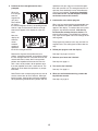
Serial Number Decal
Model No. WLTL49907.0
Serial No.
CAUTION
Read all precautions and instruc-
tions in this manual before using
this equipment. Save this manual
for future reference.
USER'S MANUAL
QUESTIONS?
As a manufacturer, we are com-
mitted to providing complete cus-
tomer satisfaction. If you have
questions, or if parts are missing,
PLEASE DO NOT CONTACT THE
STORE; please contact
Customer Care.
IMPORTANT: You must note the
product model number and
serial number (see the drawing
above) before contacting us:
CALL TOLL-FREE:
1-866-699-3756
Mon.–Fri. 6 a.m.–6 p.m. MST
Sat. 8 a.m.–4 p.m. MST
ON THE WEB:
www.wesloservice.com
Write the serial number in the
space above for future reference.

TABLE OF CONTENTS
WARNING DECAL PLACEMENT . . . . . . . . . . . . . . . . . . . . . . . . . . . . . . . . . . . . . . . . . . . . . . . . . . . . . . . . . . . . . .2
IMPORTANT PRECAUTIONS . . . . . . . . . . . . . . . . . . . . . . . . . . . . . . . . . . . . . . . . . . . . . . . . . . . . . . . . . . . . . . . .3
BEFORE YOU BEGIN . . . . . . . . . . . . . . . . . . . . . . . . . . . . . . . . . . . . . . . . . . . . . . . . . . . . . . . . . . . . . . . . . . . . . .5
ASSEMBLY . . . . . . . . . . . . . . . . . . . . . . . . . . . . . . . . . . . . . . . . . . . . . . . . . . . . . . . . . . . . . . . . . . . . . . . . . . . . . . .6
O
PERATION AND ADJUSTMENT . . . . . . . . . . . . . . . . . . . . . . . . . . . . . . . . . . . . . . . . . . . . . . . . . . . . . . . . . . . .10
HOW TO FOLD AND MOVE THE TREADMILL . . . . . . . . . . . . . . . . . . . . . . . . . . . . . . . . . . . . . . . . . . . . . . . . . .17
TROUBLESHOOTING . . . . . . . . . . . . . . . . . . . . . . . . . . . . . . . . . . . . . . . . . . . . . . . . . . . . . . . . . . . . . . . . . . . . .19
EXERCISE GUIDELINES . . . . . . . . . . . . . . . . . . . . . . . . . . . . . . . . . . . . . . . . . . . . . . . . . . . . . . . . . . . . . . . . . . .21
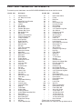
PART LIST . . . . . . . . . . . . . . . . . . . . . . . . . . . . . . . . . . . . . . . . . . . . . . . . . . . . . . . . . . . . . . . . . . . . . . . . . . . . . .23
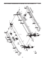
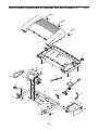
EXPLODED DRAWING . . . . . . . . . . . . . . . . . . . . . . . . . . . . . . . . . . . . . . . . . . . . . . . . . . . . . . . . . . . . . . . . . . . .24
ORDERING REPLACEMENT PARTS . . . . . . . . . . . . . . . . . . . . . . . . . . . . . . . . . . . . . . . . . . . . . . . . . .Back Cover
LIMITED WARRANTY . . . . . . . . . . . . . . . . . . . . . . . . . . . . . . . . . . . . . . . . . . . . . . . . . . . . . . . . . . . . . .Back Cover
2
WESLO is a registered trademark of ICON IP, Inc.
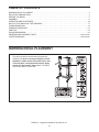
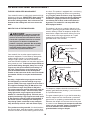
WARNING DECAL PLACEMENT
The decals shown here have been placed on the
treadmill. If a decal is missing or illegible, call the
telephone number on the front cover of this man-
ual and request a free replacement decal. Apply
the decal in the location shown. Note: The decals
may not be shown at actual size.

1. Before beginning any exercise program, con-
sult your physician. This is especially impor-
tant for persons over the age of 35 or persons
with pre-existing health problems.
2. It is the responsibility of the owner to ensure
that all users of this treadmill are adequately
informed of all warnings and precautions.
3. Use the treadmill only as described.
4. Place the treadmill on a level surface, with at
least 8 ft. (2.4 m) of clearance behind it and 2
ft. (0.6 m) on each side. Do not place the
treadmill on any surface that blocks air open-
ings. To protect the floor or carpet from dam-
age, place a mat under the treadmill.
5. Keep the treadmill indoors, away from mois-
ture and dust. Do not put the treadmill in a
garage or covered patio, or near water.
6. Do not operate the treadmill where aerosol
products are used or where oxygen is being
administered.
7. Keep children under the age of 12 and pets
away from the treadmill at all times.
8. The treadmill should be used only by persons
weighing 300 lbs. (136 kg) or less.
9.
Never allow more than one person on the
treadmill at a time.
10. Wear appropriate exercise clothes when
using the treadmill. Do not wear loose clothes
that could become caught in the treadmill.
Athletic support clothes are recommended for
both men and women.
Always wear athletic
shoes. Never use the treadmill with bare feet,
wearing only stockings, or in sandals.
11.
When connecting the power cord (see page
10), plug the power cord into a surge sup-
pressor (not included) and plug the surge
suppressor into a grounded circuit capable of
carrying 15 or more amps. No other appliance
should be on the same circuit. Do not use an
extension cord.
12. Use only a single-outlet surge suppressor
that meets all of the specifications described
on page 10. To purchase a surge suppressor,
see your local WESLO dealer or call the tele-
phone number on the front cover of this man-
ual and order part number 146148, or see
your local electronics store.
13.
Failure to use a properly functioning surge
suppressor could result in damage to the con-
trol system of the treadmill. If the control sys-
tem is damaged, the walking belt may change
speed, accelerate, or stop unexpectedly,
which may result in a fall and serious injury.
14. Keep the power cord and the surge suppres-
sor away from heated surfaces.
15. Never move the walking belt while the power
is turned off. Do not operate the treadmill if
the power cord or plug is damaged, or if the
treadmill is not working properly. (See TROU-
BLESHOOTING on page 19 if the treadmill is
not working properly.)
16. Read, understand, and test the emergency
stop procedure before using the treadmill (see
HOW TO TURN ON THE POWER on page 12
).
17. Never start the treadmill while you are stand-
ing on the walking belt. Always hold the
handrails while using the treadmill.
18. The treadmill is capable of high speeds.
Adjust the speed in small increments to avoid
sudden jumps in speed.
19.
The pulse sensor is not a medical device.
Various factors, including the user's move-
ment, may affect the accuracy of heart rate
readings. The pulse sensor is intended only
as an exercise aid in determining heart rate
trends in general.
WARNING: T
o reduce the risk of serious injury, read all important precautions and in-
structions in this manual and all warnings on your treadmill before using your treadmill. ICON as-
sumes no responsibility for personal injury or property damage sustained by or through the use of
this product.
IMPORTANT PRECAUTIONS
3

4
20. Use the dumbbells only as described in this
manual. Properly store the dumbbells in the
dumbbell holders on the console when you
are not using them. If the dumbbells are im-
properly stored, they may fall off the console,
c
ausing the user to trip.
2
1. Never leave the treadmill unattended while it
is running. Always remove the key, unplug
the power cord, and switch the reset/off cir-
cuit breaker to the off position when the
treadmill is not in use. (See the drawing on
page 5 for the location of the circuit breaker.)
22. Do not attempt to raise, lower, or move the
treadmill until it is properly assembled. (See
ASSEMBLY on page 6, and HOW TO FOLD
AND MOVE THE TREADMILL on page 17.)
You must be able to safely lift 45 lbs. (20 kg)
to raise, lower, or move the treadmill.
23. When folding or moving the treadmill, make
sure that the storage latch is fully closed.
24. Never insert any object into any opening on
the treadmill.
25. Inspect and properly tighten all parts of the
treadmill regularly.
26.
DANGER: Always unplug the power
c
ord immediately after use, before cleaning the
treadmill, and before performing the mainte-
nance and adjustment procedures described in
this manual. Never remove the motor hood un-
less instructed to do so by an authorized ser-
vice representative. Servicing other than the
procedures in this manual should be performed
by an authorized service representative only.
27. This treadmill is intended for in-home use
only. Do not use this treadmill in a commer
-
cial, rental, or institutional setting.
SAVE THESE INSTRUCTIONS

5
T
hank you for selecting the revolutionary WESLO
®
C
ADENCE 65 CROSSTRAINER treadmill. The
CADENCE 65 CROSSTRAINER treadmill offers an
impressive array of features designed to make your
workouts at home more enjoyable and effective. And
when you’re not exercising, the unique CADENCE 65
CROSSTRAINER treadmill can be folded up, requiring
less than half the floor space of other treadmills.
For your benefit, read this manual carefully before
using the treadmill. If you have questions after read-
ing this manual, please see the front cover of this man-
u
al. To help us assist you, note the product model
n
umber and serial number before contacting us. The
model number and the location of the serial number
decal are shown on the front cover of this manual.
To avoid a registration fee for any service needed
under warranty, you must register the treadmill at
www.wesloservice.com/registration.
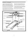
Before reading further, please review the drawing
below and familiarize yourself with the labeled parts.
BEFORE YOU BEGIN
Handrail
Upright
Storage Latch
Key/Clip
Reset/Off
Circuit Breaker
Walking Belt
Cushioned Walking Platform
Foot Rail
Power Cord
Rear Roller
Adjustment Bolts
Console
*To purchase dumbbells (not in-
cluded), call the telephone number
on the front cover of this manual.
Fan
Dumbbell/Water Bottle Holder*
Handgrip Pulse Sensor

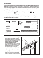
1. Make sure that the power cord is unplugged.
With the help of a second person, carefully tip
the treadmill onto its left side as shown. Partially
fold the Frame (58) so the treadmill is more sta-
ble. Do not fully fold the Frame until the
treadmill is completely assembled.
Insert an Extension Leg (89) into the base of the
Uprights (84). Hold an Extension Leg Nut (67) in
the bottom of the Extension Leg, and thread a
2.25" Extension Leg Bolt (92) with a Star
Washer (8) into the top of the Extension Leg.
Next, thread a 2.5" Extension Leg Bolt (65) with a
Star Washer (8) into the bottom of the Extension
Leg.
Firmly tighten the Extension Leg Bolts.
Slide a Front Endcap (44) onto the base of the
Upright (84). Partially tighten a Front Endcap
Screw (14) into the Front Endcap and the base.
6
ASSEMBLY
T
o hire an authorized service technician to assemble the treadmill, call 1-800-445-2480. Assembly requires
two persons. Set the treadmill in a cleared area and remove all packing materials. Do not dispose of the packing
materials until assembly is completed. Note: The underside of the treadmill walking belt is coated with high-perfor-
mance lubricant. During shipping, a small amount of lubricant may be transferred to the top of the walking belt or
the shipping carton. This is a normal condition and does not affect treadmill performance. If there is lubricant on
top of the walking belt, simply wipe off the lubricant with a soft cloth and a mild, non-abrasive cleaner.
Assembly requires the included hex key and your own Phillips screwdriver (with a shaft at
least 6" long) and wire cutters .
Use the drawings below to identify the assembly hardware. The number in parentheses below each drawing is
the key number of the part, from the PART LIST near the end of the manual. The number after the parentheses
shows the quantity needed for assembly. Note: If a part is not in the parts bag, check to see if it is preat-
tached to one of the parts to be assembled. Extra hardware may be included. To avoid damaging plastic
parts, do not use power tools for assembly.
89
58
44
84
92
8
8
14
67
65
Wheel Nut (13)–2
1
Wheel Nut (32)–2
1" Tek Screw (83)–2
2 1/2” Bolt (37)–2
Handrail Bolt (64)–4
Washer (38)–4
1
3
1/2” Bolt (45)–4
Star Washer
(106)–4
Extension Leg Bolt (96)–4
3 ( )
Star Washer
(84)–2
Star Washer (8)–8
Extension Leg Nut (67)–2
Screw (3)–11
Handrail Bolt (64)–4
Ground Screw
(33)–1
Front Endcap
Screw (14)–2
Extension Leg Bolt (96)–4
2.5" Extension Leg Bolt (65)–2
2.25" Extension Leg Bolt (92)–2
1

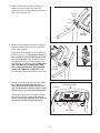
4. With the help of a second person, carefully raise
the Uprights (84) to a vertical position.
Have the second person hold the Handrail (20)
near the Uprights (84). Insert the Wire Harness
(77)
into the hole in the bottom of the Handrail
and out of the top as shown.
Next, set the Handrail (20) on the Uprights (84).
Do not let the Wire Harness (77) fall into the
right Upright.
Attach the Handrail (20) with four Handrail Bolts
(64) and four Star Washers (8); start all four
Handrail Bolts and then firmly tighten them.
See steps 1 and 2. Fully tighten the two
Front Endcap Screws (14).
7
84
20
8
8
77
64
64
2. With the help of a second person, carefully tip
the treadmill onto its right side. Do not fully fold
t
he Frame (58) until the treadmill is com-
pletely assembled.
Insert the other Extension Leg (89) into the base
of the Uprights (84). Hold an Extension Leg
Nut (67) in the bottom of the Extension Leg, and
thread a 2.25" Extension Leg Bolt (92) with a
Star Washer (8) into the top of the Extension
Leg. Next, thread a 2.5" Extension Leg Bolt (65)
with a Star Washer (8) into the bottom of the
Extension Leg.
Firmly tighten the Extension
Leg Bolts.
Slide the other Front Endcap (44) onto the base
of the Upright (84). Partially tighten a Front
Endcap Screw (14) into the Front Endcap and
the base.
89
65
44
84
14
8
8
92
67
2
3. Attach two Base Pads (82) to the base of the
Uprights (84) with two 1" Tek Screws (83).
84
83
83
82
82
3
4
58

7.
Set the console assembly on the Handrail (20).
Be careful to avoid pinching any of the
wires. Make sure that the ground wire (see
step 5) and the wire from the console assem
-
bly (see step 6) are in the indicated channel.
Hand tighten five Screws (3) into the Handrail
(20) and the console assembly. Do not put
Screws into the two indicated holes. Start all
five Screws, but do not tighten them yet.
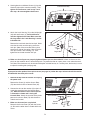
6. While the second person continues to hold the
console assembly, locate the wire underneath
the console assembly.
Connect the wire from the console assembly to
the Wire Harness (77).
See the inset drawing.
The connectors should slide together easily
and snap into place. If the connectors do not
slide together easily and snap into place, turn
one connector and then try again. IF THE CON-
NECTORS ARE NOT CONNECTED PROP-
ERLY, THE CONSOLE MAY BE DAMAGED
WHEN THE POWER IS TURNED ON. Insert
the connectors downward into the Handrail (20).
8
Console Assembly
3
3
No Screws
3
20
77
Console
Assembly
77
20
7
5. While a second person holds the console as-
sembly near the Handrail (20), attach the
g
round wire to the indicated hole in the Handrail
with a Ground Screw (33).
20
H
ole
Ground
Wire
Console
Assembly
33
5
6
Wire
Channel

1. Remove the key from the console and unplug
the power cord.
Remove the Screw (3) and the Access Door
(76) from the back of the Console Base (85).
2. Connect the wire on the receiver (A) to the indi-
cated wire extending from the Console Base
(85).
Hold the receiver so the small cylinder
is oriented as shown and is facing the
Console Base. Attach the receiver to the plastic
posts on the Access Door (76) with the two in
-
cluded small screws.
3. Make sure that no wires are pinched.
Reattach the Access Door (76) with the Screw
(3). Discard the other wires included with the re-
ceiver.
9. Attach the Latch Housing (73) to the left Upright
(84) with two Screws (3); start both Screws
and then tighten them. Note: Make sure that
the large hole in the Latch Housing is on the
indicated side.
Remove the latch knob from the latch pin. Make
sure that the collar and the spring are on the
latch pin. (Note: If there are two collars, place
one on each side of the spring.) Next, insert the
latch pin into the Latch Housing (73). Then,
tighten the latch knob onto the latch pin.
9
If you purchase the optional chest pulse sensor (see page 16), follow the steps below to install the receiver
included with the chest pulse sensor.
A
85
Small
Cylinder
3
76
Wire
Small Screws
3
Latch
Pin
Spring
Collar
Latch Knob
73
10. Make sure that all parts are properly tightened before you use the treadmill. If there are sheets of clear
plastic on the treadmill decals, remove the plastic. To protect the floor or carpet, place a mat under the tread-
mill. Note: Extra hardware may be included. Keep the included hex key in a secure place; the hex key is used
to adjust the walking belt (see page 20).
84
Large Hole
8. Hand tighten four additional Screws (3) into the
H
andrail (20) and the console assembly. Then,
tighten all nine Screws used in step 7 and
this step; do not overtighten the Screws.
Console Assembly
3
3
3
20
8
9

10
OPERATION AND ADJUSTMENT
T
HE PRE-LUBRICATED WALKING BELT
Your treadmill features a walking belt coated with high-
performance lubricant. IMPORTANT: Never apply sil-
icone spray or other substances to the walking
belt or the walking platform. Such substances will
deteriorate the walking belt and cause excessive
wear.
HOW TO PLUG IN THE POWER CORD
Your treadmill, like any other type of sophisticated
electronic equipment, can be seriously damaged by
sudden voltage changes in your home’s power.
Voltage surges, spikes, and noise interference can
result from weather conditions or from other appliances
being turned on or off. To decrease the possibility of
your treadmill being damaged, always use a surge
suppressor with your treadmill (see drawing 1 at
the right). To purchase a surge suppressor, see
your local WESLO dealer or call the telephone
number on the front cover of this manual and order
part number 146148, or see your local electronics
store.
Use only a single-outlet surge suppressor that is
UL 1449 listed as a transient voltage surge sup-
pressor (TVSS). The surge suppressor must have a
UL suppressed voltage rating of 400 volts or less
and a minimum surge dissipation of 450 joules.
The surge suppressor must be electrically rated for
120 volts AC and 15 amps. There must be a moni-
toring light on the surge suppressor to indicate
whether it is functioning properly. Failure to use a
properly functioning surge suppressor could result
in damage to the control system of the treadmill. If
the control system is damaged, the walking belt
may change speed, accelerate or stop unexpect-
edly, which may result in a fall and serious injury.
This product must be grounded.
If it should malfunc-
tion or break down, grounding provides a path of least
resistance for electric current, reducing the risk of elec-
t
ric shock. This product is equipped with a cord having
an equipment-grounding conductor and a grounding
plug.
Plug the power cord into a surge suppressor,
and plug the surge suppressor into an appropriate
outlet that is properly installed and grounded in
accordance with all local codes and ordinances.
Important: The treadmill is not compatible with
GFCI-equipped outlets.
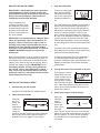
This product is for use on a nominal 120-volt circuit,
and has a grounding plug that looks like the plug illus-
trated in drawing 1 below. A temporary adapter that
looks like the adapter illustrated in drawing 2 may be
used to connect the surge suppressor to a 2-pole
receptacle as shown in drawing 2 if a properly
grounded outlet is not available.
The temporary adapter should be used only until a
properly grounded outlet (drawing 1) can be installed
by a qualified electrician.
The green-colored rigid ear, lug, or the like extending
from the adapter must be connected to a permanent
ground such as a properly grounded outlet box cover.
Whenever the adapter is used it must be held in place
by a metal screw.
Some 2-pole receptacle outlet box
covers are not grounded. Contact a qualified elec-
trician to determine if the outlet box cover is
grounded before using an adapter.
DANGER: Improper connection
of the equipment-grounding conductor can
result in an increased risk of electric shock.
Check with a qualified electrician or service-
man if you are in doubt as to whether the
product is properly grounded. Do not modify
the plug provided with the product—if it will
not fit the outlet, have a proper outlet
installed by a qualified electrician.
1
2
Grounded Outlet Box
Grounded Outlet Box
Grounding Plug
Surge Suppressor
Surge Suppressor
Grounding Pin
Adapter
Lug
Metal Screw
Grounded Outlet
Grounding Pin

1
1
ETPF59806
PFTL59806
FEATURES OF THE CONSOLE
The revolutionary treadmill console offers a selection
of features designed to make your workouts more
effective.
When you select the manual mode of the console, you
can change the speed and incline of the treadmill with
the touch of a button. As you exercise, the console will
display continuous exercise feedback. You can even
measure your heart rate using the handgrip pulse sen-
sor or the optional chest pulse sensor (see page 16 for
information about the optional chest pulse sensor).
The console also features six interactive cross trainer
programs designed to help you to burn calories and
enhance your cardiovascular system while toning and
strengthening your muscles. The cross trainer pro-
grams automatically control the speed and incline of
the treadmill and prompt you to perform a variety of
strength exercises during your workout. There are two
whole body, two upper body, and two lower body cross
trainer programs to choose among. Note: The strength
exercises require the use of dumbbells and an inflat-
able exercise ball (not included).
To purchase dumb-
bells or an exercise ball, call the telephone number
on the front cover of this manual.
To use the manual mode of the console, follow the
steps beginning on page 12. To use a cross trainer
program, see page 14.
IMPORTANT: If there is a sheet of clear plastic on
the face of the console, remove the plastic. To pre-
vent damage to the walking platform, wear clean
athletic shoes while using the treadmill.
The first
time the treadmill is used, observe the alignment of
the walking belt, and center the walking belt if nec-
essary (see page 20).
Note: The console can display speed and distance in
either miles or kilometers. To find out which unit of
measurement is selected or to change the unit of mea-
surement, see THE INFORMATION MODE on page
16
.
For simplicity, all instructions in this section refer to
miles.
Clip
CONSOLE DIAGRAM
Key

12
HOW TO TURN ON THE POWER
I
MPORTANT: If the treadmill has been exposed to
cold temperatures, allow it to warm to room tem-
p
erature before turning on the power. If you do not
do this, the console displays or other electrical
components may become damaged.
Plug in the power cord
(see page 10). Next, locate
the reset/off circuit breaker
on the treadmill frame near
the power cord. Make sure
that the circuit breaker is in
the “reset” position.
IMPORTANT: The console features a display demo
mode, designed to be used if the treadmill is dis-
played in a store. If the displays light as soon as
you plug in the power cord and switch the circuit
breaker to the reset position, the demo mode is
turned on. To turn off the demo mode, see THE IN-
FORMATION MODE on page 16 to turn off the
demo mode.
Next, stand on the foot rails of the treadmill. Locate the
clip attached to the key (see the drawing on page 11),
and slide the clip securely onto the waistband of your
clothes. Then, insert the key into the console. After a
moment, the displays will light. IMPORTANT: In an
emergency situation, the key can be pulled from
the console, causing the walking belt to slow to a
stop. Test the clip by carefully taking a few steps
backward; if the key is not pulled from the console,
adjust the position of the clip.
HOW TO USE THE MANUAL MODE
1. Insert the key into the console.
See HOW TO TURN ON THE POWER above.
2. Select the manual mode.
When the
key is in-
serted, the
manual
mode will be
selected. If
a program
has been selected, reselect the manual mode by
pressing any of the three Programs buttons re-
peatedly until a track appears in the display.
3. Start the walking belt.
T
o start the walking belt,
press the Start button,
t
he Speed increase but-
ton, or one of the speed
buttons numbered 1 to
10.
If the Start button or the Speed increase button is
pressed, the walking belt will begin to move at 1
mph. As you exercise, change the speed of the
walking belt as desired by pressing the Speed in-
crease and decrease buttons. Each time you
press a button, the speed setting will change by
0.1 mph; if you hold down a button, the speed set-
ting will change in increments of 0.5 mph. Note:
After you press the buttons, it may take a moment
for the walking belt to reach the selected speed set-
ting.
If you press one of the numbered speed buttons,
the walking belt will gradually change speed until it
reaches the selected speed setting.
To stop the walking belt, press the Stop button.
The time will begin to flash in the display. To
restart the walking belt, press the Start button, the
Speed increase button, or one of the numbered
speed buttons.
4. Change the incline of the treadmill as desired.
To change the incline of
the treadmill, press the
Incline increase and de-
crease buttons. Each
time you press a button,
the incline will change by
0.5%. Note: After you press the buttons, it may
take a moment for the treadmill to reach the se-
lected incline setting.
5.
Follow your progress with the display.
When you
select the
manual
mode, the
display will
show a track
that repre-
sents 1/4 mile. As you walk or run, indicators will
appear in succession around the track until the en
-
tire track appears. The track will then disappear
and the indicators will again begin to appear in
succession.
Track
Reset
Position
Track

13
The left side of the display
will show the elapsed
t
ime, the distance that
you have walked or run,
a
nd the incline level of the
treadmill. Note: When a
program is selected, the display will show the time
remaining in the program instead of the elapsed
time.
The right side of the dis-
play will show the ap-
proximate number of
calories you have
burned while walking or
running, the speed of the
walking belt, and your pace in minutes per mile.
The right side of the display will also show your
heart rate when you use the handgrip pulse sensor
or the optional chest pulse sensor.
To reset the display, press the Stop button, remove
the key, and then reinsert the key.
6. Measure your heart rate if desired.
Note: If you use the handgrip pulse sensor and
the optional chest pulse sensor at the same
time, the console will not display your heart
rate accurately.
Before using the handgrip pulse sensor, remove
the sheets of clear plastic from the metal contacts.
In addition, make sure that your hands are clean.
To measure
your heart
rate, stand
on the foot
rails
and
hold the
metal con-
tacts on the
handrail—avoid moving your hands. When your
pulse is detected, one or two dashes will appear in
t
he right side of the display and then your heart
rate will be shown.
For the most accurate heart
r
ate reading, continue to hold the contacts for
about 15 seconds.
7. Turn on the fan if desired.
The fan features low and high speed settings.
Press the Fan button repeatedly to select a fan
speed or to turn off the fan. Note: If the fan is on
when the walking belt is stopped, the fan will turn
off automatically after a few minutes.
8. When you are finished exercising, remove the
key from the console.
Step onto the foot rails, press the Stop button, and
adjust the incline of the treadmill to the lowest
setting. The incline must be at the lowest setting
when you fold the treadmill to the storage posi-
tion, or you may damage the treadmill.
Next, re-
move the key from the console and put it in a secure
place.
When you are finished using the treadmill, switch
the reset/off circuit breaker to the “off” position and
unplug the power cord. IMPORTANT: If you do
not do this, the treadmill’s electrical compo-
nents may wear prematurely.
Contacts

14
HOW TO USE A CROSS TRAINER PROGRAM
1
. Insert the key into the console.
S
ee HOW TO TURN ON THE POWER on page
12.
2. Select one of the six cross trainer programs.
To select a
cross trainer
program,
press one of
the three
Programs
buttons re-
peatedly
until “P 1,”
“P 2,” “P 3,” “P 4,” “P 5,” or “P 6” appears in the
display. When a cross trainer program is selected,
the program time will appear in the display, the
maximum incline setting of the program and the
maximum speed setting of the program will flash in
the display for a few seconds, and a profile of the
speed settings of the program will scroll across the
matrix in the display.
3. Press the Start button or the Speed increase
button to start the program.
A moment after you press the button, the treadmill
will automatically adjust to the first speed and in-
cline settings of the program. Hold the handrails
and begin walking.
Each program is divided into 25, 30, or 45 one-
minute segments. One speed setting and one in-
cline setting are programmed for most segments.
Note: The same speed setting and/or incline setting
may be programmed for two or more consecutive
segments. During other segments, the console will
prompt you to perform strength exercises.
During the
program, the
p
rofile will
show your
p
rogress. The
flashing seg-
ment of the
profile represents the current segment of the pro-
gram. The height of the flashing segment indicates
the speed setting for the current segment. At the
end of each segment, a series of tones will sound
and the next segment of the profile will begin to
flash. If a different speed or incline setting is pro-
grammed for the next segment, the speed or incline
setting will flash in the display to alert you.
The program will continue in this way until the last
segment of the profile flashes in the display and
the last segment ends. The walking belt will then
slow to a stop.
If the speed or incline setting for the current seg-
ment is too high or too low, you can manually over-
ride the setting by pressing the Speed and Incline
buttons. Every few times a Speed button is
pressed, an additional indicator will appear or dis-
appear in the Current Segment column.
However,
when the current segment of the program ends,
the treadmill will automatically adjust to the
speed and incline settings for the next segment.
To stop the program at any time, press the Stop
button. To restart the program, press the Start but-
ton or the Speed increase button. The walking belt
will begin to move at 1 mph. When the next seg-
ment of the program begins, the treadmill will auto-
matically adjust to the speed and incline settings for
that segment.
Current Segment

4. Perform the first strength exercise when
prompted.
When the
f
irst strength
exercise
segment be-
gins (only
one indicator
will flash in
the Current Segment column), the walking belt will
slow to a stop and the name of the first strength
exercise will appear in the display for a few sec-
onds.
Next, the
display will
show the
recom-
mended
number of
repetitions
for the first strength exercise.
Remove the clip from the waistband of your
clothes, step off the treadmill, and prepare to begin
the first strength exercise. Every few seconds, the
console will sound a tone; when a tone sounds,
perform one repetition of the exercise. Exercise
with a slow, steady motion; do not perform more
than one repetition each time a tone sounds. The
display will count down the repetitions as you per-
form them.
Note: Refer to the accompanying exercise chart to
see the correct form for each exercise. When per-
forming lunges, alternate legs with each repetition.
When performing dumbbell rows, perform half the
repetitions with your right arm and half the repeti-
tions with your left arm. The strength exercises re-
q
uire the use of dumbbells and an inflatable exer-
cise ball (not included).
To purchase dumbbells
o
r an exercise ball, call the telephone number
on the front cover of this manual.
5. Continue the cross trainer program.
When you have performed the recommended num-
ber of repetitions, the words PRESS START will
appear in the display. To continue the cross trainer
program, step onto the treadmill,
slide the clip
back onto the waistband of your clothes, and
press the Start button. The treadmill will automati-
cally adjust to the speed and incline settings for the
next segment.
The program will continue in this way until the last
segment ends. The walking belt will then slow to a
stop.
6.
Follow your progress with the display.
See step 5 on pages 12 and 13.
7.
Measure your heart rate if desired.
See step 6 on page 13.
8.
Turn on the fan if desired.
See step 7 on page 13.
9.
When you are finished exercising, remove the
key from the console.
See step 8 on page 13.
15

16
THE INFORMATION MODE
T
he console features an information mode that keeps
track of treadmill usage information. The information
m
ode also allows you to select miles or kilometers as
the unit of measurement and to turn on and turn off the
demo mode.
To select the information mode, hold down the Stop
button, insert the key into the console, and then release
the Stop button. When the information mode is se-
lected, the following information will appear in the dis-
play:
The center of
the display will
show the total
number of hours
that the treadmill
has been oper-
ated. The lower
part of the dis-
play will show
total number of miles or kilometers that the walking belt
has moved. In addition, an “E” for English miles or an
“M” for metric kilometers will appear in the lower part of
the display. To change the unit of measurement, press
the Speed increase button.
Note: The console features a display demo mode, de-
signed to be used if the treadmill is displayed in a
store. While the demo mode is turned on, the console
will function normally when you plug in the power cord,
switch the reset/off circuit breaker to the reset position,
and insert the key into the console. However, when
you remove the key, the displays will remain lit, al-
though the buttons will not function. If the demo mode
is turned on, a “d” will appear in the display while the in-
formation mode is selected. To turn on or turn off the
demo mode, press the Speed decrease button.
To exit the information mode, remove the key from the
console.
THE OPTIONAL CHEST PULSE SENSOR
A
n optional chest pulse sensor offers hands-free oper-
ation as it tracks your heart rate during your workouts.
T
o purchase the optional chest pulse sensor, call
the telephone number on the front cover of this
manual.

17
HOW TO FOLD AND MOVE THE TREADMILL
HOW TO FOLD THE TREADMILL FOR STORAGE
B
efore folding the treadmill, adjust the incline to the
lowest position. If you do not do this, you may damage the
treadmill when you fold it. Next, unplug the power cord.
CAUTION: You must be able to safely lift 45 lbs. (20 kg) to
raise, lower, or move the treadmill.
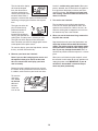
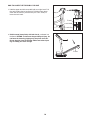
1. Hold the metal frame firmly in the location shown by the
arrow at the right. CAUTION: To decrease the possibility
of injury, do not lift the frame by the plastic foot rails.
Make sure to bend your legs and keep your back straight.
As you raise the frame, make sure to lift with your legs
rather than with your back.
Raise the frame about halfway
to the vertical position.
2. Move your right hand to the position shown and hold the
treadmill firmly. Using your left hand, pull the latch knob to
the left and hold it. Raise the frame until the latch pin is
aligned with the gap between the frame and the foot rail.
Slowly release the latch knob.
Make sure that the latch pin
is fully inserted between the frame and the foot rail.
To protect the floor or carpet from damage, place a mat
under the treadmill. Keep the treadmill out of direct sun-
light. Do not leave the treadmill in the storage position in
temperatures above 85° F (30° C).
HOW TO MOVE THE TREADMILL
Before moving the treadmill, convert the treadmill to the storage
position as described above. Make sure that the latch pin is
fully inserted between the frame and the foot rail.
1. Hold the upper ends of the handrails. Place one foot against
one of the wheels.
2. Tilt the treadmill backward until it rolls freely on the front
wheels. Carefully move the treadmill to the desired location.
To reduce the risk of injury, use extreme caution while
moving the treadmill. Do not move the treadmill over an
uneven surface.
3. Place one foot against one of the wheels, and carefully lower
the treadmill until it is resting in the storage position.
Engaged
Frame
Latch Knob
Latch Pin
Wheel
Handrail
Frame

18
HOW TO LOWER THE TREADMILL FOR USE
1. Hold the upper end of the treadmill with your right hand. Pull
the latch knob to the left and hold it. Pivot the frame down-
ward until the frame is past the latch pin. Then, slowly re-
lease the latch knob.
2. Hold the metal frame firmly with both hands, and lower it to
the floor. CAUTION: To decrease the possibility of injury, do
not lower the frame by gripping only the plastic foot rails.
Do not drop the frame to the floor. Make sure to bend your
legs and keep your back straight.
Open
Frame
Latch Knob
Latch Pin
Frame

19
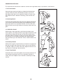
TROUBLESHOOTING
Most treadmill problems can be solved by following the steps below. Find the symptom that applies, and
follow the steps listed. If you need further assistance, please call the telephone number on the front
c
over of this manual.
PROBLEM: The power does not turn on
SOLUTION:
a. Make sure that the power cord is plugged into a surge suppressor, and that the surge suppressor
is plugged into a properly grounded outlet (see page 10). Use only a single-outlet surge suppres-
sor that meets all of the specifications described on page 10.
IMPORTANT: The treadmill is not
compatible with GFCI-equipped outlets.
b. After the power cord has been plugged in, make sure that the key is inserted into the console.
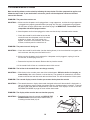
c. Check the reset/off circuit breaker located on the
treadmill frame near the power cord. If the switch
protrudes as shown, the circuit breaker has
tripped. To reset the circuit breaker, wait for five
minutes, and then press the switch back in.
PROBLEM: The power turns off during use
SOLUTION: a. Check the reset/off circuit breaker (see the drawing above). If the circuit breaker has tripped, wait
for five minutes and then press the switch back in.
b. Make sure that the power cord is plugged in. If the power cord is plugged in, unplug it, wait for
five minutes, and then plug it back in.
c. Remove the key from the console. Reinsert the key into the console.
d. If the treadmill still will not run, see the front cover of this manual.
PROBLEM: The incline of the treadmill does not change correctly
SOLUTION: a. With the key in the console, press one of the Incline buttons. While the incline is changing, re-
move the key. After a few seconds, re-insert the key. The treadmill will automatically rise to the
maximum incline level and then return to the minimum level. This will recalibrate the incline system.
PROBLEM: The console displays remain lit when you remove the key from the console
SOLUTION: a. The console features a display demo mode, designed to be used if the treadmill is displayed in a
store. If the displays remain lit when you remove the key, the demo mode is turned on. To turn off
the demo mode, hold down the Stop button for a few seconds. If the displays are still lit, see THE
INFORMATION MODE on page 16 to turn off the demo mode.
PROBLEM: The display of the console does not function properly
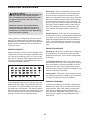
SOLUTION:
a. Remove the key from the console and UNPLUG THE
POWER CORD. Remove the three Hood Screws (7).
Carefully pivot the Hood (41) off.
Tripped
Reset
c
41
7
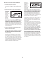
a

Locate the Reed Switch (63) and the Magnet (46) on
the left side of the Front Roller (47). Turn the Front
R
oller until the Magnet is aligned with the Reed Switch.
Make sure that the gap between the Magnet and
t
he Reed Switch is about 1/8 in. (3 mm).
I
f neces-
sary, loosen the 3/4" Screw (7), move the Reed Switch
slightly, and retighten the Screw. Reattach the Hood
(41) (not shown), making sure that the Hood Screws
(7) (not shown) are inserted into the same holes from
which they were removed. Run the treadmill for a few
minutes to check for a correct speed reading.
PROBLEM: The walking belt slows when walked on
SOLUTION: a. Use only a single-outlet surge suppressor that meets all the specifications described on page 10.
b. If the walking belt is overtightened, treadmill perfor-
mance may decrease and the walking belt may be-
come damaged. Remove the key and
UNPLUG THE
POWER CORD
. Using the hex key, turn both rear
roller bolts counterclockwise, 1/4 of a turn. When the
walking belt is properly tightened, you should be able
to lift each edge of the walking belt 2 to 3 in. (5 to 8
cm) above the walking platform. Be careful to keep
the walking belt centered. Then, plug in the power
cord, insert the key, and run the treadmill for a few
minutes. Repeat until the walking belt is properly tight-
ened.
c. If the walking belt still slows when walked on, please see the front cover of this manual.
PROBLEM: The walking belt is off-center or slips when walked on
SOLUTION:
a. If the walking belt is off-center, first remove the key
and UNPLUG THE POWER CORD. If the walking
belt has shifted to the left, use the hex key to turn
the left rear roller bolt clockwise 1/2 of a turn; if the
walking belt has shifted to the right, turn the left
bolt counterclockwise 1/2 of a turn.
Be careful not to
overtighten the walking belt. Then, plug in the power
cord, insert the key, and run the treadmill for a few
minutes. Repeat until the walking belt is centered.
b. If the walking belt slips when walked on, first re-
move the key and UNPLUG THE POWER CORD.
Using the hex key, turn both rear roller bolts clock
-
wise, 1/4 of a turn. When the walking belt is correctly
tightened, you should be able to lift each edge of the
walking belt 2 to 3 in. (5 to 8 cm) above the walking
platform. Be careful to keep the walking belt centered.
Then, plug in the power cord, insert the key, and care-
fully walk on the treadmill for a few minutes. Repeat
until the walking belt is properly tightened
.
b
a
46
6
3
7
T
op
View
1
/8 in.
47
20
Rear Roller Bolts
2–3 in.
b
Page is loading ...
Page is loading ...
Page is loading ...
Page is loading ...
Page is loading ...
Page is loading ...
Page is loading ...
Page is loading ...
-
 1
1
-
 2
2
-
 3
3
-
 4
4
-
 5
5
-
 6
6
-
 7
7
-
 8
8
-
 9
9
-
 10
10
-
 11
11
-
 12
12
-
 13
13
-
 14
14
-
 15
15
-
 16
16
-
 17
17
-
 18
18
-
 19
19
-
 20
20
-
 21
21
-
 22
22
-
 23
23
-
 24
24
-
 25
25
-
 26
26
-
 27
27
-
 28
28


Ask a question and I''ll find the answer in the document
Finding information in a document is now easier with AI
Related papers
-
Weslo Cadence 45 Treadmill User manual
-
Weslo WLTL21430 User manual
-
-
-
Pro-Form PFTL39110.1 User manual
-
-
-
-
-
Other documents
-
Kmart 43297818 User manual
-
ProForm 831.24646.0 User manual
-
-
-
-
-
-
-
NordicTrack NTL19010.0 Incline Trainer X9i User manual
-