Page is loading ...

Intel NetStructure
®
ZT 4807
Packet Switched Rear Panel
Transition Board
Technical Product Specification
Document Number: 302768

Revision History
Revision
Date
Revision History
11/16/01 Initial Release
1/17/02 Added note saying Ethernet is not functional on standard product.
Updated Functional Block Diagram.
Clarified power connector documentation.
Added floppy/IDE power cable descriptions.
CTs 6-16 have been removed from the product and documentation.
3/20/02 Documented IDE/floppy cable A86460-001. Removed references to obsolete cables
18031 and 19021.
1/08/03 Corrected Customer Support Information.
5/28/03 Added Warranty information.
7/04 Faceplate change to remove Ethernet ports.
3/24/06 Removed Ethernet connectors J3, J18 and J20.
INFORMATION IN THIS DOCUMENT IS PROVIDED IN CONNECTION WITH INTEL® PRODUCTS. EXCEPT AS PROVIDED IN INTEL’S TERMS
AND CONDITIONS OF SALE FOR SUCH PRODUCTS, INTEL ASSUMES NO LIABILITY WHATSOEVER, AND INTEL DISCLAIMS ANY EXPRESS
OR IMPLIED WARRANTY RELATING TO SALE AND/OR USE OF INTEL PRODUCTS, INCLUDING LIABILITY OR WARRANTIES RELATING TO
FITNESS FOR A PARTICULAR PURPOSE, MERCHANTABILITY, OR INFRINGEMENT OF ANY PATENT, COPYRIGHT, OR OTHER
INTELLECTUAL PROPERTY RIGHT.
Intel Corporation may have patents or pending patent applications, trademarks, copyrights, or other intellectual property rights that relate to the
presented subject matter. The furnishing of documents and other materials and information does not provide any license, express or implied, by
estoppel or otherwise, to any such patents, trademarks, copyrights, or other intellectual property rights.
Intel products are not intended for use in medical, life saving, life sustaining, critical control or safety systems, or in nuclear facility applications.
Intel may make changes to specifications and product descriptions at any time, without notice.
Designers must not rely on the absence or characteristics of any features or instructions marked “reserved” or “undefined.” Intel reserves these for
future definition and shall have no responsibility whatsoever for conflicts or incompatibilities arising from future changes to them.
The Intel NetStructure
®
ZT 4807 may contain design defects or errors known as errata which may cause the product to deviate from published
specifications. Current characterized errata are available on request.
This manual as well as the software described in it is furnished under license and may only be used or copied in accordance with the terms of the
license. The information in this manual is furnished for informational use only, is subject to change without notice, and should not be construed as a
commitment by Intel Corporation. Intel Corporation assumes no responsibility or liability for any errors or inaccuracies that may appear in this
document or any software that may be provided in association with this document.
Except as permitted by such license, no part of this document may be reproduced, stored in a retrieval system, or transmitted in any form or by any
means without the express written consent of Intel Corporation.
Contact your local Intel sales office or your distributor to obtain the latest specifications and before placing your product order.
Copies of documents which have an ordering number and are referenced in this document, or other Intel literature may be obtained by calling
1-800-548-4725 or by visiting Intel's website at http://www.intel.com.
Intel, Intel Centrino, Intel logo, Intel NetStructure, and Pentium III are trademarks or registered trademarks of Intel Corporation or its subsidiaries in the
United States and other countries.
*Other names and brands may be claimed as the property of others.
Copyright © 2001-2006, Intel Corporation
. All rights reserved.

Contents
1. INTRODUCTION....................................................................................................................................................8
UNPACKING...............................................................................................................................................................8
PRODUCT DEFINITION...............................................................................................................................................8
FEATURES OF THE ZT 4807.....................................................................................................................................9
FUNCTIONAL BLOCKS .............................................................................................................................................10
Rear-Panel I/O..................................................................................................................................................10
PS/2 Keyboard/Mouse Port............................................................................................................................10
Video Interface.................................................................................................................................................11
Universal Serial Bus........................................................................................................................................11
Serial Port Connectors (COM1 and COM2).................................................................................................11
EIDE Interface..................................................................................................................................................11
Speaker Connector..........................................................................................................................................12
Floppy Drive Interface and Power Connector..............................................................................................12
2. COMPACTFLASH OPTION...............................................................................................................................13
COMPACTFLASH INPUT CHARACTERISTICS ...........................................................................................................13
CompactFlash Card Installation and Removal............................................................................................14
3. CONFIGURATION...............................................................................................................................................15
ZT 4807 SWITCH OPTIONS AND LOCATIONS.........................................................................................................15
Switch Descriptions .........................................................................................................................................15
CUTTABLE TRACES.................................................................................................................................................17
Cuttable Trace Descriptions...........................................................................................................................17
A. SPECIFICATIONS ..............................................................................................................................................20
ELECTRICAL SPECIFICATIONS ................................................................................................................................20
ENVIRONMENTAL SPECIFICATIONS.........................................................................................................................20
MECHANICAL SPECIFICATIONS...............................................................................................................................20
Board Dimensions and Weight ......................................................................................................................21
Connectors........................................................................................................................................................22
Cables................................................................................................................................................................30
B. AGENCY APPROVALS.....................................................................................................................................31
CE CERTIFICATION.................................................................................................................................................31
SAFETY....................................................................................................................................................................31
EMISSIONS TEST REGULATIONS.............................................................................................................................31
EN 50081-1 Emissions....................................................................................................................................31
EN 55024 Immunity.........................................................................................................................................31
REGULATORY INFORMATION...................................................................................................................................32
FCC (USA)........................................................................................................................................................32
Industry Canada (Canada).............................................................................................................................32
PRODUCT SAFETY INFORMATION ...........................................................................................................................32
Safety Precautions...........................................................................................................................................32
AC and/or DC Power Safety Warning (AC and/or DC Powered Units) ...................................................34
Rack Mount Enclosure Safety........................................................................................................................34
D. INTEL NETSTRUCTURE
®
COMPUTE BOARDS & PLATFORM PRODUCTS.......................................35
LIMITED WARRANTY................................................................................................................................................35
3

Contents
C. CUSTOMER SUPPORT.....................................................................................................................................37 T
TECHNICAL SUPPORT AND RETURN FOR SERVICE ASSISTANCE...........................................................................37
SALES ASSISTANCE................................................................................................................................................37
4

Tables
Revision History............................................................................................................................2
CompactFlash Input Characteristics...........................................................................................13
Cuttable Trace Definitions...........................................................................................................17
Connector Assignments..............................................................................................................22
J5 Rear-Panel User I/O Connector Pinout..................................................................................24
J6 Speaker Connector Pinout.....................................................................................................25
J8/J9 Power Connector Pinout....................................................................................................25
J10 Floppy Drive Cable Connector Pinout..................................................................................26
J11 EIDE Connector Pinout........................................................................................................27
J13/J14 Universal Serial Bus Connector Pinout .........................................................................28
J15 Keyboard/Mouse Connector Pinout .....................................................................................28
J16/J17 COM1/COM2 Connectors Pinout..................................................................................29
J19 VGA Interface Connector Pinout..........................................................................................29
5

Figures
Functional Block Diagram...........................................................................................................10
Switch and Cuttable Trace Locations..........................................................................................18
Board Dimensions.......................................................................................................................21
Connector Locations...................................................................................................................23
Backplane Connectors—Pin Locations.......................................................................................23
6

Document Organization
This Technical Product Specification describes the operation and use of the Intel
NetStructure
®
ZT 4807 Packet Switched Rear Panel Transition Board. The following
summarizes the focus of each major section of this Specification.
Chapter 1, “
Introduction,” introduces the key features of the ZT 4807. It includes a
product definition, a list of product features, a functional block diagram, and a brief
description of each block.
Chapter 2, “
CompactFlash Option” details how to use a CompactFlash expansion card to
provide external solid-state secondary IDE channel capacity.
Chapter 3, “
Configuration,” describes factory default settings and board options
configurable through the ZT 4807’s switches and cuttable traces.
Appendix A, “
Specifications,” contains the electrical, environmental, and mechanical
specifications for the ZT 4807. It provides an illustration of connector locations, connector
descriptions, and tables of the connector pin assignments. It also presents information on
cabling recommended by Intel.
Appendix B, “
Agency Approvals,” presents agency approvals and certifications pending
for the ZT 4807.
Appendix C, “
Customer Support,” provides technical and sales assistance information.
7

1. Introduction
This chapter provides a brief introduction to the Intel NetStructure
®
ZT 4807 Packet
Switched Rear Panel Transition Board (RPIO). It includes a product definition, a list of
product features, a “
ZT 4807 Connector Plate” figure, a functional block diagram, and a
description of each block.
See Chapter 3, “
Configuration,” for factory default settings and board options configurable
through the ZT 4807’s switches and cuttable traces.
See Appendix A, “
Specifications,” for complete power and temperature requirements, as
well as connector locations, descriptions, pinout tables, and cable recommendations.
Unpacking
Please check the shipping carton for damage. If the shipping carton and contents are
damaged, notify the carrier and Intel for an insurance settlement. Retain the shipping carton
and packing material for inspection by the carrier. Do not return any product to Intel without
a Return Material Authorization (RMA) number. The "
Technical Support/Return for Service"
topic in Appendix A provides contact information for obtaining an RMA number from Intel.
Warning: Like all equipment utilizing MOS devices, the ZT 4807 must be protected from
static discharge. Never remove any of the socketed parts except at a static-free
workstation. Use the anti-static bag shipped with your order to handle the boards.
Product Definition
The ZT 4807 is a single slot, 6U board providing rear-panel access to the I/O functions of
an Intel NetStructure
®
processor board with RPIO pin compatibility (see the pin definitions
for connector
J5 in Appendix A). An example of a compatible board is the Intel
NetStructure
®
ZT 5504. The ZT 4807 is designed to function only in the RPIO slot of a
6U CompactPCI* system such as the Intel NetStructure
®
ZT 5090 4U General Purpose
Packet Switched Platform.
8

1. Introduction
Features of the ZT 4807
• Rear-panel interface connectors for host processor
board:
− USB 0 and USB1 ports
− VGA
− PS/2 Keyboard/Mouse
− COM 1
− COM 2
• Internal interfaces not on the connector plate:
− CompactFlash interface
− IDE interface (Host processor board secondary
channel)
− 4-pin power connector for external media
− Floppy interface
− PC speaker connector
• Reset Switch
• NMI Switch
9

1. Introduction
Functional Blocks
Below is a functional block diagram of the ZT 4807. The topics following the diagram
provide overviews of the ZT 4807's functional blocks.
Functional Block Diagram
ZT 4807
SPEAKER
J5
VIDEO
(J19)
USB 0
(J13)
USB 1
(J14)
COM2
(J17)
COM1
(J16)
(J10)
(J11-J12)
(J6)
KEYBOARD
& MOUSE
(J15)
FLOPPY
EIDE
(CompactFlash and
Secondary Channels)
POWER OUT
(J9)
Rear-Panel I/O
POWER IN
(J8)
Rear-Panel I/O
The ZT 4807 transitions signals from a pin-compatible processor board (such as the
ZT 5504 from Intel) through backplane connectors
J5.
PS/2 Keyboard/Mouse Port
The ZT 4807 provides rear-panel access to the host processor board keyboard/mouse
interface. The host processor board PS/2 style mouse/keyboard controller is connected via
RPIO connector
J5 to 6-pin DINN connector J15, labeled KY/MS on the ZT 4807 Connector
Plate
. Using J15 for both the PS/2 keyboard and PS/2 mouse connection requires use of a
PC keyboard/mouse ‘Y’ splitter cable. See the “
Cables” topic in Appendix A for cabling
recommendations.
Note: The keyboard and mouse do not function properly if devices are connected to both the Host
processor board and the ZT 4807.
10

1. Introduction
Video Interface
The ZT 4807 provides rear-panel access to the host processor board VGA accelerator. The
host processor board VGA accelerator is connected via RPIO connector
J5 to J19, a 15-pin
VGA connector on the
ZT 4807 Connector Plate.
Note: Video does not function properly if devices are connected to both the Host processor board
and the ZT 4807.
Universal Serial Bus
The ZT 4807 provides rear-panel access to the host processor board Universal Serial Bus
(USB) signals. The host processor board USB is connected via RPIO connector
J5 to USB
connectors
J13 and J14 on the ZT 4807 Connector Plate.
Serial Port Connectors (COM1 and COM2)
The ZT 4807 provides rear-panel access to the host processor board serial ports. The host
processor board COM1 and COM2 ports are connected via RPIO connector
J5 to 9-pin D-
shell connectors
J16 and J17, respectively, on the ZT 4807 Connector Plate.
Note: The COM Ports do not function properly if devices are connected to the same COM port
channel on both the host processor board and the ZT 4807.
EIDE Interface
The host processor board secondary channel is connected via RPIO connector J5 to
internal 40-pin 0.1” vertical header
J11 and to internal CompactFlash connector J12 on the
ZT 4807.
Only two IDE devices can be connected on any IDE channel. If the ZT 4807 has a
CompactFlash device installed, only a single IDE device can be connected to secondary
IDE channel connector J11. Refer to Chapter 2, “
CompactFlash Option,” for installation and
configuration of the ZT 4807 for operation with a CompactFlash device.
Caution: For proper operation, Intel recommends an ATA-5 compliant 80-conductor IDE
cable for external IDE connection. If the external IDE device is configured in a
master/slave combination with an on-board IDE device (CompactFlash or processor
board-mounted hard disk), a custom 80-conductor IDE cable must be used. Use of
industry standard 80-conductor IDE cables in this configuration can cause BIOS drive
detection and configuration errors. See the “
Cables” topic in Appendix A for cabling
recommendations.
An IDE drive that requires +12V/GND/+5V to operate can be connected to power output
connector
J9. Input power connector J8 must then be connected to a power source
supplying +12V/GND/+5V. Refer to the “
Cables” topic in Appendix A for more information.
11

1. Introduction
Speaker Connector
The host processor board speaker interface is connected via RPIO connector J5 to internal
speaker connector
J6, allowing connection of a PC speaker.
Floppy Drive Interface and Power Connector
The host processor board floppy drive controller is connected via RPIO connector J5 to
internal 34-pin floppy drive cable connector
J10. The ZT 4807 also provides a 4-pin power
connector (
J9) that provides +5V, GND, and +12V when input power connector J8 is
connected to an appropriate power source.
Caution: If power is supplied to J8 from the host processor board and the device connected
to J9 draws more power than the host processor board can provide, a power fault or other
problems may occur.
12

2. CompactFlash Option
CompactFlash connector J12 on the ZT 4807 provides external, solid state, secondary IDE
channel capability to a processor board such as the Intel NetStructure
®
ZT 5504 System
CPU Board with Intel Pentium
®
III processor. This connector is designed to accommodate
CompactFlash expansion cards operating in True IDE Mode, which appear to the system
as a hard drive and are automatically supported by most operating systems.
CompactFlash Input Characteristics
By default, the ZT 4807’s CompactFlash socket (J12) is set to 5.0V operation (CT5 is in
position B). This setting requires the CompactFlash card to have “Type 2” or “Type 3” input
characteristics, as shown in the “CompactFlash Input Characteristics” table below.
SanDisk* currently manufactures cards meeting these specifications.
CompactFlash Input Characteristics
Min Typ. Max Min Typ. Max
Type Parameter Symbol
VCC = 3.3 (CT5A)
1
VCC = 5.0 (CT5B)
2
Units
Input Vih 2.4 — — 4.0
3
— —
1
Voltage CMOS Vil — — 0.6
— — 0.8
Volts
Input Vih 1.5 — — 2.0 — —
2
Voltage CMOS Vil — — 0.6 — — 0.8
Volts
Input Vth — 1.8 — — 2.8 —
3
Voltage CMOS Vtl — 1.0 — — 2.0 —
Volts
Notes:
This table is based on one provided in the CompactFlash Specification Revision 1.3. The shaded area
represents operation not supported on the ZT 4807.
1. If the CompactFlash socket (J12) is set for VCC = 3.3V operation (CT5 is in the A position), do not connect
a disk drive on the EIDE connector J11. Doing so will damage the CompactFlash device!
2. Factory default configuration.
3. CompactFlash cards with “Type 1” input characteristics (operating from VCC = 5.0) should not be used
because the ZT 4807 does not meet the 4.0V minimum input voltage requirement (ZT 4807 EIDE channels
V
OH
= 2.8V).
13

2. CompactFlash Option
5.0V operation has the advantage of allowing master/slave operation, with an additional
drive connected to the secondary IDE connector
J11 on the ZT 4807. See the “SW4-1
(Secondary IDE Master/Slave Selection)” topic in Chapter 3, “Configuration,” for more
information about configuring the CompactFlash card as a master or slave IDE device on
the secondary channel.
Caution: If a CompactFlash device is present, and an IDE device is connected to J11, a
custom 80-conductor IDE cable must be used. Use of industry standard 80-conductor IDE
cables in this configuration can cause BIOS drive detection and configuration errors. See
the “
Cables” topic in Appendix A for cabling recommendations.
CompactFlash Card Installation and Removal
Perform the steps below to install or remove a CompactFlash card.
Caution: Perform the installation and removal at a static-free workstation to avoid damage
to the ZT 4807.
Installation
1. Make sure the system is powered off.
2. Put on an anti-static grounding strap.
3. Most CompactFlash cards have an arrow on the top label indicating correct orientation.
Align the arrow on the CompactFlash card with the arrow on the connector and slide the
card into place until the connection is snug. The dimensions of the grooves in the sides
of the CompactFlash card prevent incorrect installation.
Removal
1. Make sure the system is powered off.
2. Put on an anti-static grounding strap.
3. Grasp the card by the sides and pull it out of the connector. Do not apply pressure to
the top of the CompactFlash cards: this can damage some CompactFlash devices such
as the IBM Microdrive*.
14

3. Configuration
The ZT 4807 includes several options that tailor the operation of the board to requirements
of specific applications. Some options are configured with a switch or by cuttable traces.
Configure a switch option by closing or opening a DIP switch. Configure a cuttable trace
option by installing or removing a surface mount 0 Ω resistor.
ZT 4807 Switch Options and Locations
The ZT 4807 includes one bank of switches (SW4) located on the component side of the
board. See the “
Switch and Cuttable Trace Locations” figure for the location of the SW4.
SW1 is incorporated into the lower board ejector mechanism. SW2 and SW3 are push-
button switches located on the connector plate. See the “
ZT 4807 Connector Plate” figure in
Chapter 1 for the location of the SW2 and SW3.
Switch Descriptions
The following topics list the switches in numerical order and provide a detailed description
of each switch. Note that where switches are referenced in this Chapter, “SWx”
corresponds to the switch number and “-N” corresponds to the switch segment (for
example, SW2-1 means “switch number 2, segment 1”).
SW1 (Hot Swap Ejector)
The lower ejector incorporates an ejector switch, connected to the processor board’s
Baseboard Management Controller. This switch is used to notify the processor board of the
necessity to shut down so the ZT 4807 can be removed.
SW2 (Reset)
SW2 is a push-button on the ZT 4807's connector plate. See the “ZT 4807 Connector Plate”
figure in Chapter 1 for the location of the SW2. When pressed, SW2 issues a reset to the
host processor board. See the host processor board manual for a detailed description of the
reset feature.
SW3 (NMI)
SW3 is a push-button on the ZT 4807's connector plate. See the “ZT 4807 Connector Plate”
figure in Chapter 1 for the location of the SW3. When pressed, SW2 issues a non-maskable
interrupt to the host processor board. See the host processor board manual for a detailed
description of the reset feature.
15

3. Configuration
SW4-1 (Secondary IDE Master/Slave Selection)
SW4-1 configures the CompactFlash card (installed in J12) as a master or slave IDE device
on the secondary channel. This switch also changes the polarity of the “Cable Select” signal
available at connector
J11, pin 28.
If the CompactFlash card is the only device on the secondary IDE channel then it must be
configured as the master (SW4-1 = on).
If another IDE device is connected to the secondary IDE channel (cabled to connector J11)
then the CompactFlash should be configured as a slave (SW4-1 = off) and the other device
should be configured as the master. See the documentation supplied with your IDE device
to see how to configure it as a master.
If a CompactFlash card is not installed in J12, then SW4-1 should be off. SW4-1 affects the
“Cable Select” (J11 pin 28) signal on the IDE cable. For normal “cable select” operation
SW4-1 must be off.
A maximum of two IDE devices may be connected to the secondary channel. If you have a
CompactFlash card installed in J12 then you may have only one IDE device connected to
J11 and you must use a special cable to connect the external IDE device to J11. This cable
is available from Intel as part number ZT 90250. See the “
Cables” topic in Appendix A for
more information. If a CompactFlash card is not installed in J12 then two devices may be
installed on the cable connected to J11. A standard 80-pin (UDMA-66 compatible) cable
may be used in this case.
The ZT 4807 is supplied without a CompactFlash card installed in J12. Therefore SW4-1 is
off by default.
See the “
CompactFlash Input Characteristics” topic in Chapter 2 for more information.
SW4-2, SW4-3, SW4-4 (Reserved)
These switch segments are reserved for future use. Factory default is open.
16

3. Configuration
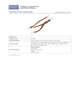
Cuttable Traces
The ZT 4807 includes several cuttable traces (0 Ω shorting resistors) that allow the user to
configure certain options not configurable through the processor board's BIOS Setup Utility.
In most cases, the default settings are appropriate for normal operation; however, some
applications may require different settings. The "
Switch and Cuttable Trace Locations"
figure shows the placement of the ZT 4807's cuttable traces.
There are two types of cuttable traces on the ZT 4807: single-option and double-option:
• Single option cuttable traces are implemented using 0603 and 1206 surface mount
pads. A 0 Ω shorting resistor is soldered between these pads to make the connection.
• Double option cuttable traces are implemented using three 0603 surface mount pads. A
0 Ω shorting resistor is soldered between one set of pads, depending on the chosen
option.
Caution: Only qualified technicians familiar with surface mount soldering techniques
should perform cuttable trace modifications. The product warranty is voided if the board is
damaged by customer modifications.
Cuttable Trace Descriptions
The “Cuttable Trace Definitions” table provides a quick cross-reference for the ZT 4807
cuttable trace descriptions that follow.
Cuttable Trace Definitions
CT# Default Description
CT1 Out Connect Top ESD Strip to Logic Ground
CT2 Out Connect Bottom ESD Strip to Logic Ground
CT3 Out Connect Reset Switch Case to Logic Ground
CT4 Out Connect NMI Switch Case to Logic Ground
CT5 B Connect Compact Flash Power to Switched 5V
17

3. Configuration
Switch and Cuttable Trace Locations
CT2
CT4
CT3
SW3
SW2
CT1
CT5
SW4
4
3
2
1
18

3. Configuration
CT1-CT4 (Connect Chassis GND to Logic GND)
The ZT 4807's switches and ejectors are on an isolated chassis ground. These components
can be connected to the ZT 4807 logic ground by installing these four cuttable traces. All
four cuttable traces should be installed or all four removed. The factory default is removed.
Position Function
All In Front panel connectors connected to logic ground
All Out Default Front-panel connectors not connected to logic ground
CT5 (CompactFlash Operating Voltage)
The factory default configuration sets the ZT 4807’s CompactFlash socket (J12) to 5.0V
operation (CT5 in position B). This setting requires the CompactFlash card to have “Type 2”
or “Type 3” input characteristics. See the “
CompactFlash Input Characteristics” table in
Chapter 3 for more information.
Caution: If the CompactFlash socket is set for VCC = 3.3V operation (CT5 is in the A
position), do not connect a disk drive on EIDE connector J11. Doing so will damage the
CompactFlash device!
Position Function
A Connects the Compact Flash Circuitry to Switched 3.3VDC.
B Default Connects the Compact Flash Circuitry to Switched 5VDC.
19

A. Specifications
This Appendix describes the electrical, environmental, and mechanical specifications of the
ZT 4807. It includes illustrations of the board dimensions and connector locations, as well
as connector pinout tables.
Electrical Specifications
Power Requirements Minimum Typical Maximum
Supply Voltage, VCC 4.75V 5.00V 5.25V
Supply Current, VCC = 5.0V 0mA -- 195mA
Environmental Specifications
Operating Temperature: 0° to +70° Celsius
Storage Temperature: -40° to +85° Celsius
Relative Humidity: < 95% at 40° Celsius, non-condensing
Mechanical Specifications
The topics listed below provide the following mechanical specifications:
• Board Dimensions and Weight
• Connectors (including connector locations, descriptions, and pinouts)
20
/