
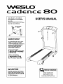
WESLO
c d nce BO
Sears Model No. 831.24602.0
Kmart Model No. WLTL29306.0
Serial No.
Write the serialnumber inthe space
above for future reference.
Serial Number
Decal
QUESTIONS?
As a manufacturer, we are com-
mitted to providing complete
customer satisfaction. If you have
questions, PLEASE CONTACT
OUR CUSTOMER SERVICE
DEPARTMENT DIRECTLY.
SEARS CUSTOMERS:
1-800-4-MY-HOME ®
(1-800-469-4663)
KMART CUSTOMERS:
1-866-699-3756
Mon.-Fri., 6 a.m.-6 p,m. MST
CAUTION
Read all precautions and Instruc-
tions in this manual before using
this equipment. Save this manual
for future reference,
USER'S MANUAL
www.weslo.com
new products, prizes,
fitness tips, and much more!

WESLO °
80
TABLE OF CONTENTS
IMPORTANT PRECAUTIONS ................................................................. 3
BEFORE YOU BEGIN ....................................................................... 5
ASSEMBLY ............................................................................... 6
OPERATION AND ADJUSTMENT ............................................................ 10
HOW TO FOLD AND MOVE THE TREADMILL .................................................. 13
MAINTENANCE AND TROUBLESHOOTING .................................................... 15
CONDITIONING GUIDELINES ............................................................... 17
ORDERING REPLACEMENT PARTS .................................................. Back Cover
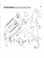
Note: A PART IDENTIFICATION CHART, an EXPLODED DRAWING, and a PART LIST are attached in the
center of this manual.
WESLO is a registered trademark of ICON IP, Inc.
2

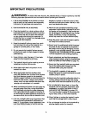
IMPORTANT PRECAUTIONS
WARNING: To reduce the risk of burns, fire, electdc shock, or injury to persons, read the
following important precautions and information before operating the treadmill.
1. It is the responsibility of the owner to ensure
that all users of this treadmill are adequately
informed of all warnings and precautions.
telephone number on the front cover of this
manual and order part number 146148, or see
your local electronics store....
2. Use the treadmill only as described.
3. Place the treadmill on a level surface, with at
least eight feet of clearance behind it and two
feet on each side. Do not place the treadmill
on any surface that blocks air openings. To
protect the floor or carpet from damage, place
a mat under the treadmill.
4. Keep the treadmill indoors, away from mois-
ture and dual Do not put the treadmill In a
garage or covered patio, or near water.
5. Do not operate the treadmill where aerosol
products are used or where oxygen is being
administered.
12. Failure to use a properly functioning surge
suppressor could result in damage to the con-
trol system of the treadmill. Ifthe control sys-
tem is damaged, the walking belt may change
speed, accelerate, or stop unexpectedly,
which may result in a fall and serious injury.
13. Keep the power cord and the surge suppres-
sor away from heated surfaces.
14. Never move the walking belt while the power
Is turned off. Do not operate the treadmill if
the power cord or plug is damaged, or if the
treadmill is not working properly. (See MAIN-
TENANCE AND TROUBLESHOOTING on page
15 if the treadmill is not working properly.)
6. Keep children under the age of 12 and pets
away from the treadmill at all times.
7. The treadmill should not be used by persons
weighing more than 250 pounds.
8. Never allow more than one person on the
treadmill at a time.
9, Wear appropdate exercise clothes when
using the treadmill. Do not wear loose clothes
that could become caught in the treadmill.
Athletic support clothes are recommended for
both men and women. Always wear athletic
shoes; never use the treadmill with bare feet,
wearing only stockings, or in sandals.
10. When connecting the power cord (see page 10),
plug the power cord into a surge suppreSsor
(not included) and plug the surge suppressor
into a grounded circuit capable of carrying 15
or more ampe. No other appliance should be on
the same circuit. Do not use an extension cord.
11. Use only a single-outlet surge suppressor that
meets all of the specifications described on
page 10. To purchase a surge suppressor, see
your local WESLO dealer or call the toll-free
15. Read, understand, and test the emergency
stop procedure before using the treadmill (see
HOW TO TURN ON THE POWER on page 11).
16. Never start the treadmill while you are stand-
ing on the walking belt. Always hold the
handrails while using the treadmill.
17. The treadmill is capable of high speeds.
Adjust the speed In small increments to avoid
sudden jumps in speed.
18. Never leave the treadmill unattended while it is
running. Always remove the key and unplug
the power cord when the treadmill is not in use.
19. Do not attempt to raise, lower, or move the
treadmill until it is propedy assembled. (See
ASSEMBLY on page 6 and HOW TO FOLD
AND MOVE THE TREADMILL on page 13.)
You must be able to safely lift 45 pounds (20
kg) to raise, lower, or move the treadmill.
20. When folding or moving the treadmill, make
sure that the storage latch is fully closed.
21. Do not change the incline of the treadmill by
placing objects under the treadmill.

22.Inspectandproperlytightenallpartsofthe scribedinthismanual.Neverremovethe
treadmillregularly, motorhoodunlessinstructedtodosobyan
authorizedservicerepresentative.Servicing
23.Neverdroporinsertanyobjectintoany otherthantheproceduresinthismanual
openingonthetreadmill, shouldbeperformedbyanauthorizedservice
representativeonly.
24DANG ER: Alwaysunplugthepower
cord immediately after use, before cleaning 25. This treadmill is intended for In-home use
the treadmill, and before performing the main- only. Do not use th s treadm I in any commer-
tenance and adjustment procedures de- clsl, rental, or institutional setting.
WARNING: Before beginning this or any exercise program, consult your physician. This
is especially important for persons over the age of 35 or persons with pre-existing health problems.
Read all Instructions before using. ICON assumes no responsibility for persona Injury or property
damage sustained by or through the use of this product.
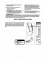
SAVE THESE INSTRUCTIONS
The decals shown here has been placed on the treadmill.
If a decal is missing, or if it is not legible, call the toll-free
telephone number on the front cover of this manual and
order a free replacement decal. Apply the decal in the lo-
cation shown. Note: The decals are not shown at actual
size.
Protect y0_rselland
o_Ps lrom nskofserious
injury R_adthe user's
manualar_ :
so_ raSt*h_
s'_i_J or ste_p_g
_dfnlL
_r_Ji roer_nts_
.H0_ ha_aib _
OOeta_l_ tread_L
.S_ _youleel_Jnt
d_z_,or shut0_
*FUI_ d0ra_
_ is rr_d _
i .K_ cl_lhi_ ¸
4

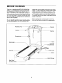
BEFORE YOU BEGIN
Thank you for selecting the WESLO _CADENCE 80
treadmill. The CADENCE 80 treadmillcombines ad-
vanced technology with innovative design to let you
enjoy an excellent form of cardiovascular exercise in
the convenience and privacy of your home. And when
you're not exercising, the unique CADENCE 80 tread-
mill can be folded up, requiring less than half the floor
space of other treadmills.
For your benefit, read this manual carefully before
you use the treadmill. If you have questions after
reading this manual, please see the front cover of this
manual. To help us assist you, note the product model
number and serial number before contacting us. The
model number is found on the front cover of this man-
ual. The serial number is found on a decal attached to
the treadmill (see the front cover of this manual for the
location of the decal).
Before reading further, please review the drawing
below and familiarize yourself with the labeled parts.
Accessory Tray
Handrail
Storage Latch
Consote
Key/Clip
Walking Belt
Hood
Reset/Off
eaker
Foot Rail
-- Power Cord
.Wheel
Rear Roller
Adjustment Bolts
Incline Pin/Leg
5

ASSEMBLY
Assembly requires two persons. Set the treadmill ina cleared area and remove all packing materials;do not
disposeofthe packingmaterialsuntilassembly iscompleted.
Note: The undersideof the treadmillwalking belt is coated with high-performance lubricant. During shipping, a
small amount of lubricant may be transferred to the top of the walking belt or the shipping carton. This does not
affect treadmill performance. If there is lubricant on top of the walking belt, simply wipe off the lubricant with a soft
cloth and a mild, non-abrasive cleaner.
In addition to the included hex key-_s , assembly requires a phillips screwdriver (_, an
adjustable wrench _, and wire cutters _.
To identify the assembly hardware, see the PART IDENTIFICATION CHART in the center of this manual.
Some parts may be preassembled. To avoid damaging plastic parts, do not use power tools for assembly.
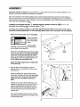
1. Make sure that the power cord is unplugged.
Have a second per-
son hold the Base
(52) in the position
shown.
Attach six Base
Pads (63) (three are shown) to the Base (52)
with six Base Pad Screws (26).
Identify the Left Upright (53), which has two small
holes near the upper end. Hold the Left Upright
so the small holes face the direction shown.
Attach the Left Uprightto the Base (52) withtwo
UprightBolts(2) and two UprightWashers (14),
Do not tighten the Upright Bolts yet.
Attach the Right Upright (54) to the Base (52)
in the same way.
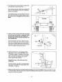
2. With the help of a second person, raise the
Uprights (53, 54) so the Base (52) is flat on the
floor as shown.
Attach the Wheels (70) (one is shown) to the
outer sides of the Base (52) with two Wheel Bolts
(35) and two Nuts (16) as shown. Do not over-
tighten the Nuts; the Wheels should turn
freely.
Position thefront end of the treadmill Frame (51)
between the Uprights (53, 54) as shown. Next, lo-
cate the long wire inside the lower end of the
Right Upright (see the inset drawing). Securely
tie the end of the wire to the end of the Wire
Harness (39).
Then, pull the opposite end ofthe wire until the
Wire Harness (39) extends from the upper end of
the Right Upright (54).
2
26
54
53
14
26
Small
Holes
51
6

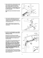
3. Have a second person lift and hold the front end
of the Frame (51). Hold a Frame Spacer (11) be-
tween the Right Upright (54) and the Frame.
Attach the Right Upright to the Frame with a
Frame Pivot Bolt (1), an Upright Washer (14), and
an Upright Star Washer (9). Do not tighten the
Frame Pivot Bolt yet.
Repeat this step on the left side of the tread-
mill.
51
4. Set the Console Assembly (91) face down on a
soft surface to avoid scratching the Console
Assembly. Set the Left Handrail (22) on the
Console as shown. Attach the Left Handrail with
two Console Screws (10).
Attach the Right Handrail (not shown) to the
other side of the Console Assembly (91) as de-
scribed above.
4
22
91
5. Hold the Console Assembly (91) near the Right
Upright (54). Touch the Right Handrail (33) to
discharge any static.
Remove the wire from the end of the Wire
Harness (39). Insert the end of the Wire Harness
through the large holes in the bottom and side of
the Right Handrail (33) and through the two
looped plasticties.
Then, press the end of the Wire Harness (39) into
the connector on the back of the Console
Assembly (91) in the location shown. See the
inset drawing. The end of the Wire Harness
should slide easily into the connector and
snap into place, Ifitdoes not, turnthe end ofthe
Wire Harness and then insert it. IF THE CONNEC-
TOR IS NOT INSERTED PROPERLY, THE
CONSOLE MAY BE DAMAGED WHEN THE
POWER IS TURNED ON.
Insert the excess Wire Harness (39) downward
into the Right Upright (54). Tighten the two plastic
ties around the Wire Harness, and then cut off the
ends of the plastic ties.
5
33
91
Connector
o
0%
39
Plastic
Ties
Connector
7

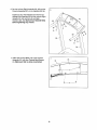
6. Set the Left and Right Handrails (22, 33) and the
Console Assembly (91) on the Uprights (53, 54).
Tighten the four Handrail Bolts (8) with the four
Handrail Star Washers (5) into the Left and Right
Uprights (53, 54) and the Left and Right
Handrails (22, 33). Start all four Handrail Bolts
before tightening any of them.
91
7. Attach the Console Back (73) to the Console
Assembly (91) withfour Console Back Screws
(4). Make sure that no wires are pinched.
7
73
91
ji /
8

8. Carefully lower the Left and Right Handrails (22,
33) until they are touching the floor.
See the lower drawing. Position the Uprights (53,
54) so that the treadmill Frame (51) is centered
between the Uprights.
Firmly tighten the four Handrail Bolts (2) and the
two Frame Pivot Bolts (1) used in steps 1 and 3.
Be careful not to overtighten the Frame Pivot
Bolts,
8
54
\
51
Top View o o
9. Attachthe Latch Housing (48) to the Left Upright
(53) with two Latch Screws (7); start both Latch
Screws before tightening them. Make sure
that the large hole in the Latch Housing is on
the indicated side,
Remove the knob from the pin. Make sure that
the collar and the spring are on the pin. (Note: If
there are two collars, place one on each side of
the spring.) Insert the pin intothe Latch Housing
(48). Then, tighten the knob onto the pin. Larg
48
10. Raise the Frame (51) to the storage position
(see HOW TO FOLD THE TREADMILL FOR
STORAGE on page 13). Attach an Incline Leg
(69) to the Frame (51) with an Incline Leg Bolt
(32), two Incline Leg Washers (43), and an
Incline Leg Nut (46) as shown.
Repeat this step on the other side of the
Frame (51),
Adjust the Incline Legs (69) to the desired level
(see HOW TO CHANGE THE INCLINE OF THE
TREADMILL on page 12).
10
11. Make sure that ell parts are properly tightened before you use the treadmill. Keep the included hex key
in a secure place. The hex key is used to adjust the walking belt (see page 16). To protect the floor or carpet,
place a mat under the treadmill.

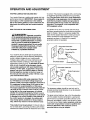
OPERATION AND ADJUSTMENT
THE PRE-LUBRICATED WALKING BELT
Your treadmillfeatures a walking belt coated with high-
performance lubricant. IMPORTANT: Never apply sil-
icone spray or other substances to the walking
belt or the walking platform. Such substances will
deteriorate the walking belt and cause excessive
wear.
HOW TO PLUG IN THE POWER CORD
DAN GER: Improper connection
of the equipment-grounding conductor can
result in an increased risk of electric shock.
Check with a qualified electrician or service-
man if you are in doubt as to whether the
product is properly grounded. Do not modify
the plug provided with the product--it it will
not fit the outlet, have a proper outlet
Installed by a qualified electrician.
Your treadmill, like any othertype of sophisticated
electronic equipment, can be seriously damaged by
sudden voltage changes in your home's power.
Voltage surges, spikes, and noise interference can
result from weather conditions or from other appli-
ances being turned on or off. To decrease the possi-
bility of your treadmill being damaged, always
use a surge suppressor with your treadmill (see
drawing 1 at the right). To purchase a surge sup-
pressor, see your local WESLO dealer or call the
toll-free telephone number on the front cover of
this manual and order part number 146148, or see
your local electronics store.
Use only a single-outlet surge suppressor that Is
UL 1449 listed as a transient voltage surge sup-
pressor (TVSS). The surge suppressor must have a
UL suppressed voltage rating of 400 volts or less
and a minimum surge dissipation of 450 joules.
The surge suppressor must be electrically rated for
120 volts AC and 15 amps. There must be a moni-
toring light on the surge suppressor to indicate
whether it is functioning properly. Failure to use a
properly functioning surge suppressor could result
in damage to the control system of the treadmill. If
the control system is damaged, the walking belt
may change speed, accelerate or stop unexpect-
edly, which may result in a fall and serious injury.
This product must be grounded. If it should malfunc-
tionor break down, groundingprovidesa path ofleast
resistancefor electriccurrent to reducethe riskofelec-
tric shock. This product isequipped with a cord having
an equipment-grounding conductor and a grounding
plug. Plug the power cord into a surge suppressor,
and plug the surge suppressor into an appropriate
outlet that is properly installed and grounded in
accordance with all local codes and ordinances.
Important: The treadmill is not compatible with
GFCI-equipped outlets.
This product is for use on a nominal 120-volt circuit,
and has a groundingplugthat looks like the plug illus-
trated indrawing 1 below. A temporary adapter that
lookslike the adapter illustratedin drawing2 may be
usedto connectthe surgesuppressor to a 2-pole
receptacleas shownin drawing 2 ifa properly
groundedoutletis not available.
_l_Grounded Outlet Box
_'-1 ._ Surge Suppressor
_p_J_.. Grounding Pin
Grounding Pin
Grounded Outlet
Grounding Plug
i_Grounded Outlet Box
Adapter ^
II ( _J _'_-_1 Surge suppressor
Metal Screw
The temporary adapter should be used only until a
properly grounded outlet (drawing 1) can be installed
by a qualified electrician.
The green-colored rigid ear, lug, or the like extending
from the adapter must be connected to a permanent
ground such as a properly grounded outlet box cover.
Whenever the adapter is used it must be held in place
by a metal screw. Some 2-pole receptacle outlet box
covers are not grounded. Contact a qualified elec-
trician to determine if the outlet box cover is
grounded before using an adapter.
10

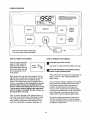
CONSOLE DIAGRAM
Note: Ifthere are sheets ofclear plas-
ticon the console,removethe plastic.
A WARNING:To_u_ ,skofs_cusinjury,
standon foot railsbefore startingt_e3dmifl,readand
_derstand the user's r_anual,aftinstructions,and the
warningsbefore use Keep childrenaway.
_ Speed
Increase
Button
HOW TO TURN ON THE POWER
Plug inthe power cord (see
page 10). Next, locate the
reset/off circuit breaker on
the treadmill frame near the
power cord. Make sure that
the circuit breaker is in the
reset position.
Reset %
Position
Next, stand on the foot rails of the treadmill. Find the
clip attached to the key (see the drawing above), and
slide the clip securely onto the waistband of your
clothes. Then, insert the key into the console. After a
moment, the displays willlight, Important: In an emer-
gency situation, the key can be pulled from the
console, causing the walking belt to slow to a stop.
Test the clip by carefully taking a few steps back-
ward; If the key is not pulled from the console, ad-
just the position of the clip.
Note: To prevent damage to the walking platform, al-
ways wear clean athletic shoes while using the tread-
mill. During the first few minutes that the treadmill is
used, inspectthe alignment of the walking belt, and
center the walking belt if necessary (see page 16).
HOW TO OPERATE THE CONSOLE
B Insert the key into the console.
See HOW TO TURN ON THE POWER at the left.
B Press the Start button or the Speed increase
button to start the walking belt.
When either button ispressed, thewalking belt will
begin to move at 1 mph. Hold the handrails and
begin walking.
As you exercise, change the speed of the walking
belt as desired by pressing the Speed Increase
and Decrease buttons. Each time a button is
pressed, the speed setting will change by 0.1
mph; if a button is held down, the speed setting
willchange in increments of 0.5 mph. Note: After a
button is pressed, it may take a moment for the
walking belt to reach the selected speed setting.
To stop the walking belt, press the Stop button.
The time will begin to flash in one of the displays.
To restart the walking belt, press the Start button or
the Speed Increase button.
11

[]
Follow your progress with the displays.
The lower left
/
display--As you exer- |
cise, the lower leftdis-
L
play can show the
elapsed time and the
distance thatyou have
walked or run.
The lower right dis-
play--The lower right
display can show the
approximatenumber of
caloriesthat you have
burnedand the speed
ofthe walking belt.
The upper
display--The
upper display
can showthe
elapsed time,
the distance
thatyou have walked or run,the approximatenum-
ber of caloriesthat you have burned, or the speed
ofthe walkingbelt. Pressthe Display buttonre-
peatedly untilthe upper displayshowsthe informa-
tionthatyou are mostinterestedinviewing. Note:
While informationisshown inthe upperdisplay,
the same information willnot be showninthe
lower leftor lowerrightdisplay.
To resetthe displays, pressthe Stop button,re-
move the key, and then reinsertthe key.
Note: The console can
display speed and dis- J_"
tance in either miles or I--
kilometers. To see
which unit of measure-
ment is selected, first
remove the key intothe console. Next, hold down
the Stop button, insert the key, wait until you hear
a tone, and then release the Stop button. An "E"
for English miles or an "M" for metric kilometers will
appear in the upper display. Press the Speed
Increase button to change the unit of measure-
ment, if desired. When the desired unit of mea-
surement is selected, remove the key and then
reinsert it into the console.
When you are finished exercising, remove the
key from the console.
Step onto the foot mils,press the Stop button, and
removethe key.Keep the key in a secure place.
Then, switch the reset/off circuit breaker to the
"off" position and unplug the power cord.
HOW TO CHANGE THE INCLINE OF THE TREADMILL
To vary the intensity of your exercise,you can change
the incline of the treadmill. There are three incline lev-
els. Before changing the incline, remove the key
and unplug the power cord. Next, fold the treadmill
tothe storageposition(see page 13).
To change the incline,first remove the inclinepin from
one of the incline legs. Adjust the incline leg to the de-
sired position, and then fully reinsert the incline pin.
Adjust the other incline leg in the same way. CAUTION;
Before using the treadmill, make sure that both in-
cline legs are at the same height and that both in-
cline pins are fully inserted into the incline legs.
Incline
Pin_
Pin
After you have adjusted the incline legs, lower the
treadmill (see page 14).
12

HOW TO FOLD AND MOVE THE TREADMILL
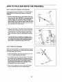
HOW TO FOLD THE TREADMILL FOR STORAGE
Unplug the power cord. CAUTION: You must be able to
safely lift 45 Ibs. (20 kg) to raise, lower, or move the
treadmill.
1. Hold the metal frame firmly in the location shown by
the arrow at the right. CAUTION: To decrease the pos-
sibility of injury, do not lift the frame by the plastic
foot rails. Make sure to bend your legs and keep your
back straight. As you raise the frame, make sure to lift
with your legs rather than your back. Raise the frame
about halfway tothe vertical position.
Frame
t
2. Move your right hand tothe position shownand hold the
treadmill firmly. Using your left hand, pull the latch knob
to the left and hold it. Raise the frame until the catch is
past the latch pin. Then, slowly release the latch knob;
make sure that the catch is resting against the latch
pin.
To protect the floor or carpet from damage, place a
mat under the treadmill. Keep the treadmill out of di-
rect sunlight, Do not leave the treadmill in the stor-
age position in temperatures above 85°F (30°C).
HOW TO MOVE THE TREADMILL
Before moving the treadmill, convert the treadmill to the stor-
age position as described above. Make sure that the catch
is resting against the latch pin.
1. Hold the handrails and place one foot against one ofthe
wheels. Do not pull back on the frame.
2. Tilt thetreadmillbackward until itmilsfreely on the wheels,
and carefully move the treadmill to the desired location.
Never move the treadmill without tipping it backward,
To reduce the risk of injury, use extreme caution
while moving the treadmill. Do not attempt to move
the treadmill over an uneven surface.
3. Place one foot against one of the wheels, and carefully
lower the treadmill until it is in the storage position.
Handrail /
13

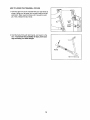
HOW TO LOWER THE TREADMILL FOR USE
1. Hold the upper end of the treadmill with your right hand as
shown. Using your left hand, pull the latch knob to the left
and hold it. Next, lower the frame until it is past the latch
pin. Then, release the latch knob.
Latch
2. Hold the frame firmly with both hands, and lower it to the
floor. To decrease the possibility of injury, bend your
legs and keep your back straight.
/
Frame
14

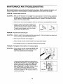
MAINTENANCE AND TROUBLESHOOTING
Most treadmill problems can be solved by following the steps below. Find the symptom that applies, and
follow the steps listed. If further assistance is needed, please see the front cover of this manual.
PROBLEM: The power does not turn on
SOLUTION: a. Make sure that the power cord isplugged intoa surge suppressor, and thatthe surge suppressor
isplugged intoa properlygroundedoutlet(see page 10). Use onlya single-outletsurgesuppres-
sorthat meets all ofthe specificationsdescribed on page 10. Important:The treadmill is not com-
patiblewith GFCI-equipped outlets.
b. After the power cord has been plugged in, make sure that the key isfully inserted intotheconsole.
c. Check the reset/off circuit breaker locatedon the
treadmillframe near the power cord. Ifthe switch
protrudesas shown, the circuitbreaker has tripped.
To resetthe circuitbreaker, wait for fiveminutes,
and then press the switch backin.
Tripped
PROBLEM: The power turns off during use
SOLUTION: a. Check the reset/offcircuitbreaker (see the drawingabove). If thecircuitbreaker has tripped,wait
forfive minutesand then press the switchback in.
b. Make sure thatthe powercord isplugged in.
c. Remove the key fromthe console. Reinsertthe key fullyintotheconsole.
d. Ifthe treadmillstillwillnot run, please see thefrontcoverofthismanual.
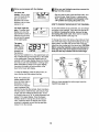
PROBLEM: The displays of the console do not function properly
SOLUTION: a. Remove the key fromthe console and UNPLUG THE
a 20
POWER CORD. Remove the five indicatedScrews 65
(20). Then, carefullyremove the Hood (65).
Locate the Reed Switch (89) and the Magnet (62) on
the left side of the Pulley (71). Turn the Pulley until the
Magnet is aligned with the Reed Switch. Make sure
that the gap between the Magnet and the Reed
Switch is about 1/8". If necessary, loosenthe Screw
(21), movethe Reed Switch slightly,and then
retightenthe Screw. Reattach the Hood (notshown),
and run the treadmill for a few minutes to check for a
correct speed reading.
TopveS l
15

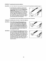
PROBLEM: The walking belt slows when walked on
SOLUTION: a. Use only a single-outlet surge suppressor that meets all of the specifications described on page 10.
b*
If the walking belt is overfightened, treadmill perfor-
mance may decrease and the walking belt may be-
come damaged. Remove the key and UNPLUG THE
POWER CORD. Using the hex key, turn both rear
roller bolts counterclockwise, 1/4 of a turn. When the
walking belt is properly tightened, you should be able
to lift each edge of the walking belt 2 to 3 inches off
the walking platform. Be careful to keep the walking
belt centered. Then, plug in the power cord, insert the
key, and run the treadmill for a few minutes. Repeat
until the walking belt is properly tightened.
Bolts
c. Ifthe walking belt still slows when walked on, see the front cover of this manual.
PROBLEM: The walking belt is oft-center or slips when walked on
SOLUTION: a.
If the walking belt has shifted to the left, first re-
move the key and UNPLUG THE POWER CORD.
Using the hex key,turnthe left rear roller boltclock-
wise 1/2 ofa turn. Be carefulnot toovertightenthe
walking belt. Ifthe walking belt has shifted to the
right, turnthe leftrear rollerboltcounterclockwise1/2
ofa turn.Then, plug inthe power cord, insert the key,
and run the treadmillfor a few minutes. Repeat until
the walkingbelt iscentered.
SOLUTION: a. If thewalking belt slips when walked on, first remove
the key and UNPLUG THE POWER CORD. Using the
hex key, turn both rear roller bolts clockwise, 1/4 of a
turn. When the walking belt is correctly tightened, you
should be able to lift each edge of the walking belt 2 to
3 inches off the walking platform. Be careful to keep
the walking belt centered. Then, plug in the power
cord, insert the key, and carefully walk on the treadmill
for a few minutes. Repeat until the walking belt is
properly tightened.
16

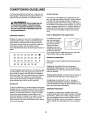
CONDITIONING GUIDELINES
The following guidelines willhelp you toplan your ex-
ercise program. Remember that proper nutrition and
adequate rest are essential for successful results.
WARNING: Beforebeginning this
or any exercise program, consult your physi-
cian. This is especially important for individu-
als over the age of 35 or individualswithpre-ex-
isting healthproblems.
EXERCISEINTENSITY
Whether your goal is to burn fat or tostrengthenyour
cardiovascular system, the key to achieving the de-
sired results is to exercise with the proper intensity.
The proper intensity level can be found by using your
heart rate as a guide. The chart below shows
recommended heart rates for fat burning and aerobic ex-
ercise.
165 155 145 140 130 125 115
145 138 130 125 118 110 103
125 120 115 110 105 95 90
20 30 40 50 60 70 80
To find the proper heart rate for you, first find your age
near the bottomofthe chart (ages are roundedoffto
the nearest tenyears). Next, find the three numbers
above your age. The three numbers are your "training
zone." The lowertwo numbers are recommended
heart ratesfor fat burning; the highestnumber isthe
recommended heart rate for aerobic exercise.
Burning Fat
To burn fat effectively, you must exercise at the proper
intensity level for a sustained period of time. During the
first few minutes of exercise, your body uses easily ac-
cessible cafbohydratecalories for energy. Only after
the first few minutes does your body begin to use
stored/a/calories for energy. If your goal isto burn fat,
adjust the intensity of your exercise until your heart
rate is between the lower two numbers in your training
zone as you exercise.
Aerobic Exercise
If your goal is to strengthen your cardiovascular sys-
tem, your exercise must be "aerobic." Aerobic exercise
is activity that requires large amounts of oxygen for
prolonged periods of time. This increases the demand
on the heart to pump blood to the muscles, and on the
lungs to oxygenate the blood. For effectiveaerobic ex-
ercise, adjust the intensity of your exercise until your
heart rate is near the highest number in your training
zone.
HOW TO MEASURE YOUR HEART RATE
To measure your heart
rate, stop exercising
and place two fingers on
your wristas shown.
Take a six-second
heartbeat count,and
multiply the resultby ten
to find your heart rate.
(A six-second count is used because your heart rate
drops quickly when you stop exercising.)
WORKOUT GUIDELINES
Each workout should include the following three impor-
tant parts:
A warm-up, consisting of five to ten minutes of
stretching and light exercise. This will increase your
body temperature, heart rate, and circulation in prepa-
ration for exercise.
Training zone exercise, including 20 to 30 minutesof
exercise withyour heart ratein yourtrainingzone.
A cool-down, consisting of five to ten minutes of
stretching. Stretchingafter exercise iseffectivefor in-
creasing flexibility and helpsto offsetproblems caused
when you stop exercisingsuddenly.
EXERCISE FREQUENCY
To maintain or improve your condition, plan three
workouts each week, with at least one day of rest after
each workout. After a few months of regularexercise,
you may complete up to five workouts each week, if
desired. Remember, the key to success is to make ex-
ercise a regular and enjoyable part of your everyday
life.
17

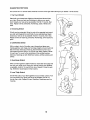
SUGGESTED STRETCHES
The correctform for several basic stretches isshown at the right. Move slowlyas you stretch--never bounce.
1. Toe Touch Stretch
Stand with your knees bent slightly and slowly bend forward from
your hips. Allow your back and shoulders to relax as you reach
down toward your toes as far as possible. Hold for 15 counts, then
relax. Repeat 3 times. Stretches: Hamstrings, back of knees and
back.
2. Hamstring Stretch
Sit with one leg extended. Bring the sole of the opposite foot toward
you and rest it against the inner thigh of your extended leg. Reach
toward your toes as far as possible. Hold for 15 counts, then relax.
Repeat 3 times for each leg. Stretches: Hamstrings, lower back and
groin.
3. Calf/Achilles Stretch
With one leg in front of the other, reach forward and place your
hands against a wall Keep your back leg straight and your back foot
flat on the floor. Bend your front leg, lean forward and move your
hips toward the wall. Hold for 15 counts, then relax. Repeat 3 times
for each leg. To cause further stretching of the achilles tendons,
bend your back leg as well. Stretches: Calves, achilles tendons and
ankles.
4. Quadriceps Stretch
With one hand against a wall for balance, reach back and grasp one
foot with your other hand. Bring your heel as close to your buttocks
as possible. Hold for 15 counts, then relax. Repeat 3 times for each
leg. Stretches: Quadriceps and hip muscles.
5. Inner Thigh Stretch
Sit with the soles of your feet together and your knees outward. Pull
your feet toward your groin area as far as possible. Hold for 15
counts, then relax. Repeat 3 times. Stretches: Quadriceps and hip
muscles.
2
18

NOTES
19

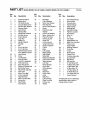
PART LIST SEARS MODEL NO. 831.24602.0; KMART MODEL NO. WLTL29306.O R0706A
Key Key Key
No. Qty. Description No. Qty. Description No. Qty. Description
1 2 Frame Pivot Bolt
2 4 UprightBolt
3 1 Tie Holder Screw
4 4 Console BackScrew
5 4 Handrail Star Washer
6 1 Warning Decal
7 2 Latch Screw
8 4 Handrail Bolt
9 2 Upright Star Washer
10 4 Console Screw
11 2 Frame Spacer
12 4 Cage Nut
13 2 incline Pin
14 6 Upright Washer
15 1 Key/Clip
16 2 Nut
17 1 6 mm Hex Key
18 1 4 mm Hex Key
19 4 Roller Bracket Screw/
Front Platform Screw
20 5 Hood Screw
21 18 Screw
22 1 Left Handrail
23 1 Ground Screw
24 1 Latch Pin Assembly
25 10 Foot Rail Screw
26 6 Base Pad Screw
27 2 Walking Platform Bolt
28 4 Belt Guide Screw
29 2 Rear Roller Adj. Bolt
30 2 Motor Bolt
31 1 Motor Pivot Bolt
32 2 Incline Leg Bolt
33 1 Right Handrail
34 2 Motor Tension Bolt
35 2 Wheel Bolt
36 2 Rear Roller
Star Washer
37 1 Reset]Off 71 1 Front Roller/Pulley
Circuit Breaker 72 1 Ground Wire
38 2 Motor Star Washer 73 1 Console Back
39 1 Wire Harness 74 2 Frame Endcap
40 1 Ground Star Washer 75 2 Base Endcap
41 11 Screw 76 1 Walking Belt
42 4 Electronics Star 77 4 Handrail Endcap
Washer 78 2 Platform Cushion
43 4 Incline Leg Washer 79 1 Drive Motor
44 2 Motor Tension Nut 80 4 Wire Tie
45 2 Frame Pivot Nut 81 4 8" Tie
46 2 Incline Leg Nut 82 2 Tie Holder
47 5 Hood Clip 83 1 Reed Switch Clip
48 1 Latch Housing 84 1 Belly Pan Grommet
49 1 Upright Grommet 85 1 Power Cord
50 2 isolator Fastener Strain Relief
51 1 Frame 86 1 Walking Platform
52 1 Base 87 1 Controller
53 1 Left Upright 88 1 Choke
54 1 Right Upright 89 1 Reed Switch
55 1 Rear Roller 90 1 Power Cord
56 1 Motor Belt 91 1 Console Assembly
57 1 Electronics Bracket 92 1 Ground Wire
58 2 Latch Catch Screw 93 2 Belt Guide
59 1 Motor Bracket 94 1 M5 Hex Key
60 1 Left Rear # 1 6" Red Wire, M/F
Roller Bracket # 1 4" Black Wire, M/F
61 1 Right Rear # 1 4" Blue Wire, M/F
Roller Bracket # 1 8" Blue Wire, 2F
62 1 Magnet # 1 10" Blue Wire, 2F
63 6 Base Pad # 1 6" White Wire, 2F
64 1 Latch Catch # 1 10" White Wire, 2F
65 1 Hood # 1 User's Manual
66 1 Belly Pan
67 1 Left Foot Rail # These parts are not illustrated.
68 1 Right Foot Rail Specifications are subject to
69 2 Incline Leg change without notice.
70 2 Wheel
Page is loading ...
Page is loading ...
Page is loading ...
-
 1
1
-
 2
2
-
 3
3
-
 4
4
-
 5
5
-
 6
6
-
 7
7
-
 8
8
-
 9
9
-
 10
10
-
 11
11
-
 12
12
-
 13
13
-
 14
14
-
 15
15
-
 16
16
-
 17
17
-
 18
18
-
 19
19
-
 20
20
-
 21
21
-
 22
22
-
 23
23


Ask a question and I''ll find the answer in the document
Finding information in a document is now easier with AI
Related papers
-
Weslo Treadmill WLTL29306.0 User manual
-
Weslo WLTL21430 User manual
-
-
-
-
Weslo G-30 Treadmill User manual
-
-
-
-
