Installation, Operating, Maintenance
and After Sales Manual.
Product Serial Number:
Please leave this manual with the end user.
Part Number: 1370056
Issue 5
heatingthroughinnovation.
HI-LINE RC & HI-LINE RC Heater/Cooler
Models: 7-4, 10-6, 15-10, 20-14
01.06.2011 ISSUE 5
23673 HiLine manual UK 27/06/2011 09:12 Page 2

1.0 General Information 03
2.0 Heating System Design 03
3.0 Unit Selection/Sizing 03
4.0 Location 03
5.0 Preparation 04
6.0 Fixing 04
7.0 Water Connections 05
8.0 Electrical Connection 06
9.0 Commissioning Procedure 06
10.0 Technical Data 08
11.0 Operating Instructions 09
12.0 Troubleshooting 10
13.0 Maintenance 11
Contents
23673 HiLine manual UK 27/06/2011 09:12 Page 3

03
HI-LINE RC & HI-LINE RC Heater/Cooler
1.0 General Information
2.0 Heating System Design
l This MYSON HI-LINE RC fan convector is designed for
wall-mounted installation with a maximum installation height
of 2.13m to the underside of the unit.
l The minimum installation height is 1.8m to the underside of
the unit.
l The minimum clearance between the top of the unit and the
ceiling should be 50mm.
l The minimum side clearance is 100mm.
l The HI-LINE RC should only be used on closed circulation,
two pipe, pump assisted central heating systems (HI-LINE) or
heating and cooling systems (HI-LINE Heater/Cooler).
l Before proceeding with the installation, the heating system
design must be considered and the unit correctly sized to
meet the heat loss requirements of the room at normal fan
speed.
l This unit is supplied with an infra red remote control system
and has 3 operating modes -
Automatic – the desired room temperature is programmed in
to the unit and the fan speed is automatically adjusted until
the desired room temperature is achieved.
Fan only – allows user selection of any of the 3 available
fan speeds irrespective of room temperature or water
temperature in the coil.
Fan only with water temperature control – allows the user to
select any of the available fan speeds, which will operate only
if the water temperature in the coil is above 32C. This enables
control of the unit via an externally mounted room thermostat
if desired.
l The appliance is not intended for use by persons (including
children) with reduced physical, sensory or mental capabilities,
or lack of experience and knowledge, unless they have been
given supervision or instruction concerning use of the
appliance by a person responsible for their safety.
Children should be supervised to ensure that they do not play
with the appliance.
This fan convector must be fitted on a two pipe, pumped
circulation heating system.
For optimum fan convector heating performance the system
must be capable of providing sufficient hot water through the
heat exchanger. This means that:
1. The minimum pipe size from boiler to fan convector must
be 15mm.
2. This unit is not suitable for use on microbore pipework.
3. Where the unit is fitted on to a system with other emitters a
separate circuit for the fan convector should be considered
to provide adequate water flow.
4. The system water must be above 32°C for heating mode.
5. For heat pump applications - see Commissioning Procedure.
6. This unit is NOT suitable for one-pipe systems.
7. Optimum performance will require effective balancing
of the whole system.
8. This unit should NOT be used to replace a radiator in an
existing system unless an adequate flow of water can be
guaranteed.
3.0 Unit Selection/Sizing
4.0 Location
l This HI-LINE RC unit may be fitted to any convenient wall at
a height from floor level that suits the application, providing
an unimpeded flow of warm air into the area to be heated.
l The maximum distance from the underside of the unit to floor
level is 2.13m.
l The minimum distance to the underside of the unit is 1.8m.
l This unit should not be installed in locations with ceiling
heights greater than 3m.
l The unit should be mounted on a flat wall, and stud or
partition walls should be avoided to minimise the possibility
of noise transmission.
l For cooling applications, the need for disposal of condensate
may influence the position of the unit.
1.02.03.04.0
This unit MUST NOT be installed in a bathroom or other similar high humidity area.
Heat output performance is given in the Technical Data section
of this manual. Outputs are shown for the 3 fan speeds,
however, it is important to size the unit to match the calculated
heat loss requirements of the room with the unit operating on
the low fan speed. The higher fan speeds are used in automatic
mode when the room temperature is significantly lower than the
preset temperature.
When establishing the temperature difference, ie mean water to
room temperature, allowance should be made for temperature
drop in the system. It is the water temperature at the unit which
dictates the output.
23673 HiLine manual UK 27/06/2011 09:12 Page 4

04
HI-LINE RC & HI-LINE RC Heater/Cooler
5.0 Preparation
Before proceeding with the installation, unpack the carton
contents and check against the checklist below:
1. HI-LINE RC fan convector.
2. 15mm isolating valves (1 pair).
3. Instruction manual.
4. Warranty card.
5. Fixing kit (rubber mounts and cable gland).
6. Remote control handset.
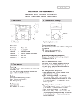
6.0 Fixing
Unit A B
Dimensions (mm)
20-14 1171 1039
15-10 887 754
10-6 682 550
7-4 554 422
A
277
59
73B
94
35
49
Fig. 1
Fig. 2 Case fixing screw positions
l Using the fixing dimensions below (see fig. 1), mark the fixing
hole positions on the wall.
l Drill and plug the wall for No. 8 x 40mm round head wood
screws ensuring that the wall plugs are suitable for the wall
type.
l Remove the backing from two of the self-adhesive washers
and place on two of the screws with adhesive side towards
the point.
l Tighten the screws into the top two fixing holes leaving about
9mm projecting.
l Press adhesive washers to the wall.
l Remove the backing from the last self-adhesive washer and
place centrally over the bottom fixing hole on the left hand
side.
Remove the outer casing as follows:
l
Remove the 2 screws at each end of the outlet grille (see fig. 2).
l Lift off the outer case.
l Fit chassis on to the top two mounting screws and tighten.
l Secure the bottom fixing point with the remaining screw.
Note: Before proceeding with pipe-work connections check that
the unit is level. If the right hand end is lower than the left then
the ability to vent the unit may be restricted.
When water connections and electrical connections have been
completed and the unit has been vented, fit the outer cover and
secure with fixing screws.
23673 HiLine manual UK 27/06/2011 09:12 Page 5

05
HI-LINE RC & HI-LINE RC Heater/Cooler
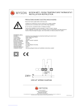
7.0 Water Connections
l Connect unit to system flow and return pipes using the two
15mm isolating valves (see fig. 3).
l Ensure system is flushed in accordance with recognised best
practice and a suitable inhibitor is added to the system as
necessary.
l Open valves fully, check pipe connections for leaks and vent
the heat exchanger - see Commissioning Procedure.
HI-LINE Heater/Cooler installations with chilled water will
require provision for condensate disposal in accordance with any
local regulations.
A drain tray is fitted for condensate collection within the unit.
This should be connected to a 15mm drain pipe.
Note: External pipe-work carrying chilled water must be
insulated. Use a suitable sealant as necessary to ensure that
condensate does not spill or leak.
202
247
79
96
56
42
170
100 min
each side
50 min
to ceiling
Fig. 3
5.0
6.07.0
23673 HiLine manual UK 27/06/2011 09:12 Page 6

06
HI-LINE RC & HI-LINE RC Heater/Cooler
8.0 Electrical Connection
WARNING: This appliance must be earthed. The electrical installation must comply with local or national
wiring regulations.
O O
LN
Brown
Blue
White
Yellow
Motor
Power Board
Control Board
Air Sensor
Water Sensor
O O
Wiring diagram
9.0 Commissioning Procedure
l Fill and vent the system.
l Open both valves fully and check for leaks at pipe
connections.
l Refit the outer case and secure using the 2 fixing screws.
l Switch on electrical supply.
l Check the operation of the unit by following the operating
instructions.
l When installation and commissioning are complete, hand over
instruction manual to end-user.
l This unit is supplied with factory fitted test leads. Remove
these and discard.
l A fused electrical spur with a maximum 3A fuse and a switch,
having 3mm separation on all poles, must be provided in an
easily accessible position adjacent to the unit.
l Electrical cable entry to the unit should be made through the
hole provided at the top left hand side of the unit, using the
cable gland provided.
l Connect live and neutral wires to the power board terminal
connections, and the earth wire to the chassis earth terminal.
23673 HiLine manual UK 27/06/2011 09:12 Page 7

07
HI-LINE RC & HI-LINE RC Heater/Cooler
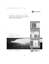
9.0 Commissioning Procedure (continued...)
1
2
3
4
Fig. 4
Switch Switch Down Switch Up
1 Auto Fan Speed Selection 2 Speed 3 Speed
2 Heating / Cooling Heating Heating & Cooling
3 Fan Pulse Off On
4 Temperature Display °F °C
8.09.0
Heat Pump and Low Water Temperature Systems
In heating mode, the control system brings the fan on when the
water in the coil reaches 32°C. For low water temperature systems,
eg heat pump systems, it is possible to switch off the boost speed
option in automatic mode so that the unit runs in medium or normal
fan speeds depending on demand. This means low outlet air
temperatures from the unit are avoided when the room temperature
is low in relation to the set temperature.
This facility can be switched on or off by following the instruction
below
l Isolate electrical supply.
l Remove outer cover.
l Change switch 1 position according to requirements
(see fig. 4).
l Refit outer cover.
l Switch on electrical supply.
Displayed Temperature Calibration
Depending on the location of the unit there may be a difference
between the temperature at the unit and the temperature in the
middle of the room being treated.
The displayed temperature calibration function enables
calibration in heating mode of the displayed temperature to the
actual room temperature using the following procedure:
l Press the On/Off key and + key simultaneously for 5 seconds.
The display will flash, alternating between ‘ro’ and the
calibration temperature.
l Calibrate the displayed temperature by using the + and – keys
with the fan running.
l Press the On/Off key to finish.
Fan Pulse
Fan pulse mode causes room air to be drawn over the air
temperature sensor periodically to maintain room temperatures
more effectively. In certain circumstances, for example when
units are over-sized in relation to the heat loss of the room, it
may be necessary to turn off this function. Use dipswitch 3
according to requirements.
23673 HiLine manual UK 27/06/2011 09:12 Page 8

08
HI-LINE RC & HI-LINE RC Heater/Cooler
10.0 Technical Data
Model Fan Speed
Heat Output (watts)
Temperature Difference (°C)
Heat Output (Btu/h)
Temperature Difference (°F)
2737 3101 3468 3836 4207 4579
3457 3917 4380 4845 5314 5784
3917 4436 4959 5485 6014 6545
1941 2199 2459 2721 2983 3248
2197 2489 2783 3079 3376 3675
2913 3300 3690 4082 4477 4873
1271 1440 1610 1781 1953 2126
1546 1752 1959 2167 2376 2587
1990 2255 2521 2789 3059 3330
734 831 930 1029 1128 1228
1020 1156 1292 1430 1568 1707
1344 1522 1702 1883 2065 2248
Normal
Medium
Boost
Normal
Medium
Boost
Normal
Medium
Boost
Normal
Medium
Boost
20-14
15-10
10-6
7-4
9339 10581 11831 13089 14354 15625
11796 13365 14944 16533 18130 19735
13363 15136 16920 18715 20518 22331
6625 7504 8391 9282 10179 11081
7495 8492 9495 10504 11519 12539
9939 11260 12591 13929 15275 16628
4336 4912 5493 6076 6664 7254
5276 5977 6684 7394 8109 8827
6971 7694 8603 9517 10437 11361
2504 2837 3172 3509 3848 4189
3481 3944 4410 4879 5350 5824
4584 5194 5807 6424 7045 7669
40° 45° 50° 55° 60° 65° 72° 81° 90° 99° 108° 117°
Cooling Performance Data
Noise Levels
Model Fan Speed
Cooling Performance (watts)
Air-Mean Water Temperature Difference (°C)
Cooling Performance (Btu/h)
Air-Mean Water Temperature Difference (°F)
1256 1034 1922 1291 2676 1421
1510 1241 2312 1597 3220 1759
1601 1363 2449 1770 3408 1879
886 761 1355 1002 1886 1091
958 815 1466 1058 2041 1123
1276 1093 1953 1434 2719 1549
578 490 884 635 1230 668
646 545 988 704 1375 736
780 638 1194 867 1662 1098
318 274 487 362 678 396
473 405 725 531 1009 574
574 459 878 623 1222 790
Normal
Medium
Boost
Normal
Medium
Boost
Normal
Medium
Boost
Normal
Medium
Boost
20-14
15-10
10-6
7-4
4284 3530 6557 4405 9131 4849
5153 4234 7887 5449 10985 6002
5462 4650 8354 6039 11628 6412
3022 2598 4624 3420 6435 3721
3268 2781 5001 3609 6965 3833
4354 3730 6664 4892 9276 5284
1971 1671 3016 2166 4195 2279
2202 1861 3370 2404 4690 2512
2662 2178 4074 2957 5671 3748
1085 936 1663 1237 2313 1352
1614 1383 2473 1813 3443 1959
1957 1567 2995 2126 4170 2695
Tot. Sens. Tot. Sens. Tot. Sens.
15° 20° 25° 27° 36° 45°
Tot. Sens. Tot. Sens. Tot. Sens.
Heat outputs tested in accordance with
BS 4856 Part 1.
Flow rate 340 ltr/h (75 gal/h).
Flow Rate Correction Factors:
455 ltr/h (100 gal/h) multiply by 1.06.
227 ltr/h (50 gal/h) multiply by 0.96.
113 ltr/h (25 gal/h) multiply by 0.85.
Noise levels tested in accordance with EN 23741.
Test Pressure 20bar (2 MPa)
Water connections 15mm
Maximum working pressure 10bar (1MPa)
Electrical supply 230V - 50Hz
Cooling performance tested in accordance with BS 4856 Part 2. Flow rate 340 ltr/h. Relative humidity 50%.
Model
Sound Pressures at 2.5m (dBA)
20-14 33.3 38.7 45.4
15-10 28.8 35.4 45.6
10-6 23.5 30.8 37.2
7-4 23.4 32.5 43.3
Normal Medium Boost
Weight, Water Content and Motor Power
Model
Motor
Power (W)
Water
Content (l)
Unpacked
Weight (kg)
20-14 80 0.30 7.4
15-10 62 0.32 8.9
10-6 35 0.56 11.3
7-4 35 0.77 14.7
Heating Performance Data
Approximate Hydraulic Resistance through Fan Convectors
Litres/h
7-4
1084
798
350
134
10-6
1240
657
327
105
15 -10
1500
905
450
157
20 -14
1774
1140
565
221
7-4
9.4
7.7
3.5
1.4
10-6
12.12
6.42
3.25
1.1
15 -10
14.7
8.9
4.37
1.57
20 -14
17.42
11.2
5.5
2.1
455
340
227
113
mm wg
kPa
23673 HiLine manual UK 27/06/2011 09:12 Page 9

09
HI-LINE RC & HI-LINE RC Heater/Cooler
11.0 Operating Instructions
Description
This HI-LINE unit is fitted with a control system that provides 3
different operating modes. In automatic mode the desired
temperature set point is selected and the unit will adjust the fan
speed according to the difference between the actual room
temperature and the set point. When the room temperature
reaches the set point the fan will switch off and thereafter will
continue to cycle on and off to maintain the room temperature.
The temperature set point range is 15 - 35°C.
In manual mode the automatic temperature control is over
ridden and any of the three fan speeds can be operated
inrespective of the water temperature in the unit. This means
that air circulation can be provided in summer for example, or
that heating performance can be controlled manually.
In manual mode, with water temperature control, any of the 3
fan speeds can be selected and the fan will operate when the
water temperature in the coil is greater than 32°C. This means
that heating performance can be controlled manually, and the
unit could be controlled via an external room thermostat.
The unit can be controlled using the infra red remote control
handset supplied with the unit (see fig. 5) and also using the
control panel on the unit (see fig. 6). If necessary, however, the
control panel can be locked electronically to prevent tampering
once the controls have been set (see over).
The remote control hand set takes 2 AAA batteries (not supplied).
Fig. 5 Fig. 6
Controls Display
Power button Switches unit on & off
‘+/-’ button Adjust temperature set point from
15 - 35°C
Scrolls into F1, F2 or F3 manual mode
Heating
The unit will only operate in heating mode when the central
heating boiler is on, the pump is running and the system
water temperature is greater than 32°C. Ensure the boiler is
on, and set timer, boiler controls and room thermostats as
necessary.
10.0
11.0
23673 HiLine manual UK 27/06/2011 09:12 Page 10

Manual
Manual mode can be used for air circulation without heat or for
manual control of the heating function.
Use ‘+’ to scroll beyond 35°C
Or use ‘-’ to scroll below 15°C
Selected fan speed displayed
Continuous
fan only
Fan & water
temperture
(water inlet >32°C)
Scrolling back out of manual using the ‘+’ or ‘–’ button will revert
the unit back to last temperature set point.
Cooling Mode
l Close the heating system and isolate any other heat emitters.
l Open the cooling water system.
l Ensure cooling is on, and set cooling unit timer and controls
as necessary.
Cooling operation works in exactly the same way as heating.
Follow the procedure above to set the unit controls.
Locking Unit Controls
The control panel on the main unit can be locked electronically
to prevent interference once the controls have been set. After
setting the unit to the desired temperature setting and with the
unit in running mode, press the On/Off button on the main unit
for about 6 seconds until the two middle horizontal bars appear
on the display. The horizontal bars will disappear after about 6
seconds and the unit is in key lock mode.
If any of the unit controls are pressed the horizontal bars will
reappear to show the key lock mode is activated, however,
during this mode the handset controls remain functional.
To unlock the system press the On/Off button for about 6
seconds until the horizontal bars disappear.
10
HI-LINE RC & HI-LINE RC Heater/Cooler
12.0 Troubleshooting
Once installed this fan convector becomes part of a complete
heating system that generally will include boiler, pump, other
emitters such as radiators and fan convectors, and a number of
heating controls, dependent on system complexity. An apparent
problem with this unit may be the result of system controls being
incorrectly set and can be solved easily without calling out your
installer or MYSON Service. Before calling your installer or
MYSON Service, please carry out the checks listed opposite.
Note: If you call out MYSON Service to a fault detailed opposite,
or to repair a fault caused by incorrect use, a call out charge will
be made.
11.0 Operating Instructions (continued...)
Operation Display
Power off No Display
Switch on supply to unit for 30 seconds
(unit off)
Supply on / unit off
Switch on unit Set point flashes for
approx 5 secs, then
Ambient temperature
displayed
Use ‘+/-’ to adjust Set point flashes for
set point approx 5 secs, then
Ambient temperature
The ambient temperature is always displayed unless the water
temperature falls below 32°C*, or if the set point is being
adjusted.
Water temp <32°C Shows both power
& unit on
*32°C in heating and above 20°C in cooling.
23673 HiLine manual UK 27/06/2011 09:12 Page 11

11
HI-LINE RC & HI-LINE RC Heater/Cooler
12.0 Troubleshooting (continued...)
Common Installation Faults
For optimum performance, this unit must be correctly sized to
match the heat loss requirements of the space it is required to
heat, and the heating system must be correctly designed to
provide adequate flow of hot water to the unit (see Section 2).
If the recommendations in Section 2 are not followed,
problems may arise as detailed below.
Heating Mode -
No Fan
Heating Mode
(Heater model only)
poor heating
performance and/or
unit cycles on
water sensor
Possible Causes
Unit switched off
Temperature set point reached
Unit not switched on at fused spur
Fuse blown at fused spur
Unit isolating valves shut
Water temperature reaching fan
convector below 32°C
(Heater model only)
Problem Remedy
Low water temperature to unit Turn up boiler thermostat
Poor water flow Vent air from heating system
Note: Operation of the fan convector can be
checked by switching to manual for setting.
Turn on
Increase temperature set point
Switch on at spur
Replace fuse
Open valves
Check boiler -
Programmer ON
Boiler ON and set to high with central
heating pump running
Note: Operation of fan convector can be checked by
switching to manual fan setting
Heating Mode
(Heater model only)
poor heating
performance and/or
unit cycles on
water sensor
Possible Causes
Boiler thermostat set too low
Lack of flow to fan convector -
Pump set on low setting
Isolating valves not fully open
System incorrectly balanced with unit starved of hot water flow
Pipe sizing to unit too small
Problem
Poor heating performance
(Heater model only)
Unit incorrectly sized for heat loss of room
13.0 Maintenance
Before undertaking any maintenance activity isolate the
electrical supply.
Maintenance should be restricted to occasional removal of dust
and lint around the unit. The outer surface may be wiped over
with warm water and mild detergent taking care to avoid water
entering the grille areas.
If the fan convector is still faulty after checking the above, call your installer or MYSON Service.
11.0
12.013.0
23673 HiLine manual UK 27/06/2011 09:12 Page 12

heatingthroughinnovation.
01.06.2011 ISSUE 5
After Sales Service:
MYSON Service, Somerden Road, Hull, East Yorkshire HU9 5PE
T: 01482 713927, F: 01482 789056, [email protected]
Spare parts and technical help on all Convector products are available from MYSON Service.
MYSON Eastern Avenue, Team Valley, Gateshead, Tyne & Wear NE11 0PG, UK
Serial Number Location:
Lower/inner chassis position facing wall
23673 HiLine manual UK 27/06/2011 09:12 Page 1
/