Page is loading ...

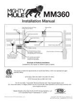
Driveway Alarm
INSTALLATION MANUAL
Rev. 1/06/10 • Printed in China for GTO, Inc.
How it works:
The Transmitter - Sensor:
The operating voltage for the transmitter is 3V from two alkaline ‘AA Size’ batteries (not included) inside
the transmitter. In cold weather lithium-alkaline batteries will perform best. There is no power switch for
this unit. Once the batteries are installed, the unit starts to function. IMPORTANT: Batteries should be installed
at the mounting location to ensure proper calibration of the sensor. You should install the batteries at the location by removing the
transmitter cover and then replacing it.
The approximate transmitting range from the transmitter to the receiver is
400 ft. (at 433MHz). The range may vary depending on environmental conditions such as RF interference,
topography and construction of the building.
The Receiver:
The receiver is powered by an external power adaptor (AC120V 60Hz / DC 12V 100 mA). A rotary switch
controls the alert buzzer’s volume on the receiver. There are three LEDs on the front panel of the cabinet,
representing power (red), visitor alert (green) and low battery (red). A “RESET” button on the front panel is
used to clear the alert LED after it has registered passing vehicles.
Thank you for purchasing the GTO Driveway Alarm. Please read the directions carefully and completely
before installing.
For more information on GTO's full line of automatic gate openers and access controls visit our web site at www.gtoinc.com
WIRELESS
Kit Includes:
• TransmitterModule
• Sensor
• Receiver
• Transformer
• Mountingpost(3pieces)
• Installationmanual
Sensor
Mounting
post
Receiver
Transformer
Transmitter

2
Driveway Alarm
Place the SENSOR immediately next to the driveway to
maximize the sensing range, but at least 25 feet from
roadways, neighbor’s driveways or large moving metal
objects.
The 15 ft. cable connecting the SENSOR and
TRANSMITTER allows for the placement of the
TRANSMITTER away from the driveway in the concealment
of landscape or closer to the RECEIVER.
The approximate transmitting range from the
TRANSMITTER to the RECEIVER is 400 ft. Range can
vary depending on environmental conditions such as RF
interference and topography. Some adjustment may be
required.
NOTE: DO NOT place the TRANSMITTER in the
direct path of a sprinkler. The module is water
resistant but not waterproof.
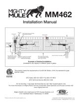
Installation Overview
Place Driveway Sensor at least
25 feet from roadways, neighbor’s
driveways to prevent false signals
Senses vehicles and
large moving metal objects
within a 12 foot radius
ROADWAY
Up to 400 foot range
from transmitter to receiver
For Optimum Performance:
• LocatetheSENSORasfaraspossibleawayfrompowertransformers,powerlines,
underground gas line, and telephone lines.
• LocatetheSENSORawayfromgeneralmovingtrafctopreventunwantedactivation.
RememberthattheSENSORdetectsMAGNETICDISTURBANCEScausedbyavehicle’s
mass and velocity.
• Rangedistanceisapproximateandwillvaryduetooutsideinterference,typeofsoil,
vehicle mass, speed, etc.
• ItisrecommendedthatyouruntheSignalCableinsidePVCconduittoprevent
accidental damage.
• DonotruntheSignalCableinconduitwithotherwiressuchasACpowerorother
control wires.
•TheSIGNALCABLECANNOTBESPLICED.Ifyouneedmorewire,contacttheGTO
SalesDepartmentat1-800-543-GATE(4283).

Driveway Alarm
3
IMPORTANT: Clear an area 25 feet in all directions
of metal tools, toys and automobiles, to prevent
magnetic disturbance during testing and installation.
•DeterminetheoptimumlocationfortheSENSOR
using the information found in “Installation
Overview.”
•Digaholeapproximately10-12inchesdeepand24
inches long within 2 feet and parallel to the edge of
the driveway.
•KeeptheSENSORandthecableuncoveredatthis
time.
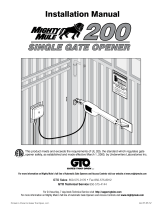
DRIVEWAY
HOUSE or BUILDING
where RECEIVER is located
ROADWAY
TRANSMITTER
400’ Max
Wireless
SENSOR RANGE:
12 ft. radius (max)
SENSOR:
2 feet from
driveway (max)
and 12” deep
25 ft. from
neighbor’s
driveway
25 ft. from
roadway
Signal Cable
Transmitter Placement
Determining Transmitter Location
Sensor Placement
Determining Sensor Location
• ChoosealocationfortheTRANSMITTERmodulethatisfar
enough from the driveway edge that vehicles are unlikely to
hit it.
• FifteenfeetofwireisincludedtoallowtheTRANSMITTERto
be 12 to 15 feet from the driveway.
• RuntheSENSORcablethroughthePVCmountingpostand
plug it into the connector at the bottom of the Transmitter
module.
•Leave2”to3”ofslackinthecabletopreventdamagetothe
connector when the transmitter is removed.
• Testthechosenlocationbeforepermanentlytrenching
andsettingtheTRANSMITTER(see“PlacingReceiverand
Testing System” section).
Connect Sensor Cable
to Transmitter Module
Leave 2” to 3” of slack
in the Sensor Cable

4
Driveway Alarm
Placing Receiver and Testing System
Receiver Placement
RESET BUTTON
LOW BATTERY LED
TRANSFORMER INPUT
VOLUMN CONTROL
VISITOR LED
POWER LED
• PlacetheindoorRECEIVERinaconvenientlocationthatis
approximately 3 ft. above the floor level.
• PlugtheACtransformerintoa110VACoutletandthe
charger cable into the receiver.
•ThepowerLEDonthefrontpanelwilllightup,andthere
willbeaconrmation“beep”tone.
• WhenacarpassestheSENSOR,asignalistransmitted
totheRECEIVERfromtheTRANSMITTERbymeansofa
433MHz carrier frequency. After the RECEIVER receives the
signal, the buzzer will “beep” twice, and the visit alert LED
(green) will flash 3 times and remain lit, until the RESET
button is pressed.
• TheLOWBATTERYLEDalertsyouwhenthetwo(2)“AA”
batteriesintheTRANSMITTERneedtobereplaced.
•TesttherangeandsystembyhavingsomeonedriveanautomobilepasttheSENSORtobesurethe
RECEIVERisactivatedwhenthevehiclehaspassedtheSENSOR.Itmaybenecessarytoadjustthe
positionoftheTRANSMITTERforoptimumresults.
Testing the System
•TemporarilyplaceTRANSMITTERonthemountingpostinground.
• WithTRANSMITTERindesiredlocationinstalltwo(2)“AA”batteries.
Installing Transmitter Batteries
IMPORTANT: “AA” batteries must be installed at the site where the TRANSMITTER will be located to ensure
proper calibration of the transmitter.
Insert
“AA” Batteries

Driveway Alarm
5
Permanently Install Sensor and Transmitter
Sensitivity Adjustment
•Oncethesystemistestedandworking,removethe
batteriesandpermanentlyinstalltheSENSOR,SIGNAL
CABLEandTRANSMITTER.
• BurytheSENSORapproximately10”-12”deep,flat
and parallel, next to the driveway.
•DiganarrowtrenchorslitfromtheSENSORtothe
TRANSMITTERlocationusingaatspadeorother
tool.ThewirefromtheSENSORtotheTRANSMITTER
should be at least six inches deep to avoid possible
damage from edgers, or lawn aerators.
• SecuretheTransmitterModuleonthesupplied3piece
PVCpipebyburyingthebottomthirdofthepipeinthe
soilandtampingthegroundaroundthepipe.DONOT
cover the electronics module with a metal cover as this
will cause signal interference.
• SecuretheTRANSMITTERmountingpostinthe
groundsothattheTRANSMITTERisuprightand
approximately 12” above ground.
• ReplacethebatteriessotheTRANSMITTERcanre-
calibrate.
Transmitter approximately
12 inches above ground
Edge of Driveway
Bury Sensor 10-12 inches deep
flat and parallel to driveway
• TheRANGEdistancecanbeadjustedfroma3to12foot
radiusfromtheSENSOR.
•Thepotentiometervariesthesensitivityrangeofthe
SENSORtoavoidunwantedmovingmetalobjectsfrom
activating the ALARM, such as: moving gates, metal play
equipment,garagedoors,othervehiculartrafc,etc.
• WiththeRANGEadjustedtothemaximumof12feet,a
largemetalobjectmovingslowlywillbedetectedupto12
feetfromtheSENSOR,whileasmallmetalobjectmoving
slowly might not be detected at the same distance. As you
moveclosertowardtheSENSOR,thesmallmovingmetal
objectwillatsomepointcauseaDISTURBANCEinthe
MAGNETICFIELDandactivatetheALARM.
MIN MAX
SENSITIVITY
TRANSMITTER CODE
TRANSMITTING
1 2 3 4
INSIDE TRANSMITTER
Sensitivity
Adjustment
Potentiometer

6
Driveway Alarm
Trouble Shooting
System not detecting vehicles:
• AretheDIPswitchesontheindoorandoutdoorunits
both set the same?
• Isthesensorinstalledclosetodrivewayasshown?
• Isthedistancetothebaseunitwellwithinmaxrange?
Remember that foliage, trees, and buildings in the
line from transmitter to indoor unit will reduce the
transmitting range.
• Metalbuildingssuchasmobilehomescanblockthe
signal. Try placing the indoor unit close to a window
facing the outdoor sensor.
• Removetheoutercoverfromtransmitterandcheck
to see if LED blinks when a vehicle passes the sensor.
The LED indicates that a vehicle was detected and it is
transmitting.
• Removethe“AA”batteries-makesurethereareno
largemetalobjectsorvehicleswithin12feetofthe
SENSOR-replacethe“AA”batteriesandallow60
seconds for it to recalibrate.
-ReplaceTRANSMITTERbatterieswhenindoor
RECEIVER’s low battery light comes on.
- In locations where weather varies extremely use
Lithium-Alkaline “AA” batteries for best performance.
Sensor detecting vehicles on the street:
• Isthesensorprobeatleast25feetfromtheedgeof
the road? Try moving the sensor farther from the road.
Remember to keep it close to the edge of the driveway.
• Adjustthesensitivitycontroltoreducesensitivity.Make
small changes until street vehicles are not detected.
Counterclockwiseadjustmentsmakethesensorless
sensitive
Indoor base unit detecting a neighbor’s driveway alert:
• SelectadifferentTRANSMITTER/RECEIVERcodeusing
the4positionDIPswitchonthetransmitterandthe
indoorunit.Bothsetsofswitchesmustbesetexactly
the same.
1 2 3 41 2 3 4
FACTORY CODE YOUR CODE
If you change your DIP switch settings make note
here for future reference.
MIN MAX
SENSITIVITY
TRANSMITTER CODE
TRANSMITTING
1 2 3 4
TRANSMITTER CODE
1 2 3 4
Code Setting
DIP Switches
INSIDE TRANSMITTER
BOTTOM OF RECEIVER
Sensitivity
Adjustment
Potentiometer
Transmitting LED
Place Driveway Sensor at least
25 feet from roadways, neighbor’s
driveways to prevent false signals
Senses vehicles and
large moving metal objects
within a 12 foot radius
ROADWAY
Up to 400 foot range
from transmitter to receiver

FCC WARNING: Changes or modications to this unit not expressly approved by the party responsible for compliance
could void the user’s authority to operate the equipment. In accordance with FCC Part 15, Section 15.21, the manufac-
turer is not responsible for any radio or TV interference caused by unauthorized modications to this equipment. Such
modications could VOID the user authority to operate the equipment.
NOTE: This equipment has been tested and found to comply with the limits for a Class B digital device, pursuant to Part
15 of the FCC Rules. These limits are designed to provide reasonable protection against harmful interference in a resi-
dential installation. This equipment generates, uses and can radiate radio frequency energy and, if not installed and used
in accordance with the instructions, may cause harmful interference to radio communications.
However, there is no guarantee that interference will not occur in particular installations. If this equipment does cause
harmful interference to radio or television reception, which can be determined by turning the equipment off and on, the
user is encouraged to try to correct the interference by one or more of the following measures: • Reorient or replace
the receiver antenna. • Increase the separation between the equipment and the receiver. • Connect the equipment into an
outlet on a circuit different from that which the receiver is connected. • Consult the dealer or an experienced radio/TV
technician for help.
GTO Limited One Year Warranty
GTO,Inc.,gateopenersandaccessoriesarecoveredunderwarrantybythemanufactureragainstdefectsinmaterialsand
manufacturer workmanship for a period of one (1) year from date of purchase, provided the recommended installation procedures
have been followed.
In the case of product failure due to defective material or manufacturer workmanship within the one (1) year warranty period, the
productwillberepairedorreplaced(atthemanufacturer’soption)atnochargetothecustomer,ifreturnedfreightprepaidtoGTO,
Inc.,3121HartseldRoad,Tallahassee,Florida,USA32303.IMPORTANT: Call (800) 543-1236 for a Return Goods Authorization
(RGA) number before returning accessory to factory. ProductsreceivedatthefactorywithoutanRGAnumberwillnotbe
accepted. Replacement or repaired parts are covered by this warranty for the remainder of the one (1) year warranty period or six (6)
months,whicheverisgreater.GTO,Inc.willpaytheshippingcharges(equaltoUnitedParcelServiceGROUNDrate)forreturntothe
owner of items repaired under warranty.
The manufacturer will not be responsible for any charges or damages incurred in the removal of the defective parts for repair, or for
the reinstallation of those parts after repair. This warranty shall be considered void if damage to the product(s) was due to improper
installationoruse,connectiontoanimproperpowersource,orifdamagewascausedbyelectricalpowersurge,lightning,wind,re,
flood, insects or other natural agent.
Aftertheone(1)yearwarrantyperiod,GTO,Inc.willmakeanynecessaryrepairsforanominalfee.CallGTOat(800)543-1236
formoreinformation.Thiswarrantygivesyouspeciclegalrights,andyoumayalsohaveotherrightswhichmayvaryfromstate
to state. This warranty is in lieu of all other warranties, expressed or implied. NOTE: Verification of the warranty period requires
copies of receipts or other proof of purchase. Please retain these records.
GTO,Inc.•3121HartseldRoad•Tallahassee,Florida32303
1-800-543-GATE(4283)•TechnicalSupport1-800-543-1236
www.gtoinc.com
For online Technical Support visit the Online Troubleshooter Wizard 24 hrs/day 7 days/week at
http://support.gtoinc.com/support/troubleshooter.aspx
and open a Tech Ticket
TechnicalSupportHours:MON-FRI8:00AM-7:00PM(ET)
(800) 543-1236
/