
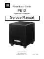
PowerBass
™
Series
PB12
Powered Subwoofer
Service Manual
JBL Consumer Products
250 Crossways Park Dr.
Woodbury, New York 11797 Rev10 2/2004

PB12 TABLE OF CONTENTS
Safety Information ………………………………………………….……….3
Basic Specifications ……………………………..………………………….4
Detailed Specifications ……………………………………….…………….5
Controls and their Function………….……..……………………………….6
Connections …………………….……………………………………………7
Operation ……………………………………………………………………10
Troubleshooting…………………………………………….……………….11
Test Setup and Procedure …………………………………………..…….12
Service Bulletin JBL 2001-03 ……………………….…………………….13
Service Bulletin JBL 2001-04 …………………………………….……….14
Service Bulletin JBL 2001-05 ……………………………….…………….17
Service Bulletin JBL 2001-07 ……………………………….…………….18
Service Bulletin JBL 2001-08 ……………………………….…………….19
Tech Tip JBLTT2003-04…………………………………..……………….20
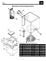
Exploded View/Packaging.……………………………………………..….21
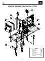
Amplifier Exploded View ………………………………………….……….22
Amplifier Faceplate/Access…………………………………………..……23
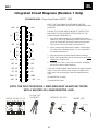
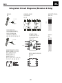
Integrated Circuit Diagrams……………………………………………….24
Testing Procedures..…………… …………………………………………26
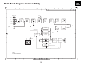
Block Diagram Revision 2…………………………………………………32
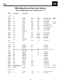
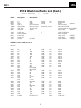
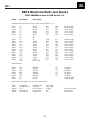
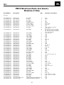
Electrical Parts List (PCB version 6.3 – 7.0)…………………………… 33
Electrical Parts List (PCB version 7.2) ……………………………..……37
Electrical Parts List Revision 2…………………………………………….41
Printed Circuit Boards (PCB version 6.3)…………………...……..…….44
Printed Circuit Boards (PCB version 6.4)………..…..……………….….47
Printed Circuit Boards (PCB version 7.2)… …………………………….48
Schematics Version 1
Preamp (PCB version 6.3)…………………………… …….……….51
Power Amp (PCB version 6.0 -6.3)…….. ………………………….52
Power Amp (PCB version 7.0)…………… …………………..…….53
Preamp (PCB version 7.2)…………………………… ……….…….54
Power Amp (PCB version 7.2)……………………………. …… ….55
Schematics Version 2……………………………………………..…….…56
PB12 – DIFFERENCES IN REVISION 1 AND REVISION 2
REVISION 1 REVISION 2
Amplifier faceplate says “Made in Canada”
Amplifier serial number starts with “AM”
Black (or silver) potted, non-serviceable output module
Amplifier serial number starts with “HA”
Output transistors in the open, on a large black heatsink
Large plastic cup enclosing the rear of the amp assembly
Main PCB, bottom, solder-side contains all SMD devices
“Made in Mexico” label on outer part of cabinet
BOTH VERSIONS OF THESE AMPLIFIERS ARE NOT CONSIDERED INTERCHANGEABLE; THEY ARE
NOT A DROP-IN REPLACEMENT IN THE CABINET OF THE OTHER VERSION.
2

PB12
3
Warning
Any person performing service of this unit will be exposed
to hazardous voltages and the risk of electric shock. It is
assumed that any person who removes the amplifier from
this cabinet has been properly trained in protecting
against avoidable injury and shock. Therefore, any service
procedures are to be performed by qualified service
personal ONLY!
Caution
Before the amplifier is plugged in, be sure its rated
voltage corresponds to the voltage of the AC power
source to be used. Incorrect voltage could cause damage
to the amplifier when the AC power cord is plugged in. Do
not exceed rated voltage by more than 10%: operation
below 90% of rated voltage will cause poor performance
or may shut the unit off.
Leakage/Resistance Check
Before returning the unit to the customer, perform a
leakage or resistance test as follows:
Leakage Current. Connect the unit to its rated power
source. Using an ammeter, measure the current between
the neutral side of the AC supply and chassis ground of
the unit under test. If leakage current exceeds 0.5mA, the
unit is defective. Reverse the polarity of the AC supply
and repeat.
Resistance. Measure the resistance from either side of the
line cord to chassis ground, If it is less than 500k ohms,
the unit is defective.
WARNING! DO NOT return the unit to the customer if it
fails one of these tests until the problem is located and
corrected.
Critical Components
All components identified with the IEC
symbol in the parts list and schematic
diagram designate components in which
safety can be of special significance when
replacing a component identified with. Use
only the replacement parts designated in the parts list or
parts with the same rating of resistance, wattage or voltage.
SAFETY INFORMATION
List of Safety Components
Requiring Exact Replacements
Revision 1 Revision 2 Description
F1 - 80117 093-105202-300 Line Fuse Slo Blo 2.0A
PWRCORD 083-041802-009 250V UL approved
80105 SPT-2 or better with
polarized plug, UL
approved wired with the
hot side to fused side.
Use with factory
replacement panel strain
relief (70305) only.
TRX 042-010053-003 Power Transformer. Use
80116 only factory replacement.
BR RECT BR1 Bridge diode. Use only
50100 052-400080-000 factory replacement.
C1,2 C6,8 Large electrolytic filter
(2200uF 100V) (3300uf 80v) caps. Be sure
30710 034-470745-200 replacement part is at
least the same working
voltage and capacitance
rating.
Also the lead spacing is
important. Incorrect
spacing may cause
premature failure due to
internal cabinet pressure
and vibration.
C10 Does not apply 4.7uF, 100 volt NPE low
30718 df radial.
(On Power amp PCB)
S64AMI Does not apply Power output module.
60302 Use only factory
replacement
Faceplate n/a Use only factory
70325 replacement
Rear Amp Cover 063-531808-000 Use only factory
Does not apply replacement
Inductor Does not apply CMC - Use only factory
80100 replacement
Inductor Does not apply L1 - Use only factory
80121 replacement
Does not apply Inductor L2 - Use only factory
043-300101-000 replacement
Does not apply Inductor L3 - Use only factory
043-700101-000 replacement

PB12
4
Output Power
250 watts RMS
Driver
12" Woofer
Frequency Response
25Hz – Low-Pass Frequency setting
Inputs
Line Level (option: LFE); Speaker Level
Outputs
Speaker level fixed frequency 150Hz
Low-Pass Frequency
Variable from 50Hz – 150Hz
High-Pass Frequency
150Hz when using Speaker Level Output
Dimensions (H x W x D)
15 1/2" x 15" x 16"
394mm x 381mm x 406mm
(with feet) 17 1/2" x 15" x 16"
445mm x 381mm x 406mm
Weight
40 lb/18.2kg
Refinements may be made on occasion to existing products without notice but will always meet or exceed original
specifications unless otherwise stated.
PowerBass is a re
g
istered trademark of JBL, Incorporated.
00261-1
BASIC SPECIFICATIONS PB12 Subwoofer

PB12
5
JBL PB12 250W Powered Sub Amp
LINE VOLTAGE Yes/No Hi/Lo Line Nom. Unit Notes
US 120vac/60Hz Yes 108-132 120 Vrms Normal Operation
EU 230vac/50-60Hz Yes 207-264 230 Vrms Normal operation, MOMS required
Parameter Specification Unit
QA Test
Li
m
i
ts
Conditions Notes
Amp Section
Type (Class AB, D, other) D n/a
n/a
Load Impedance (speaker) 5.6 Ohms
n/a
Nominal
Rated Output Power (120VAC) 250 Watts
140 Domestic version onl
y
120 VAC-60 Hz
Rated Output Power (230VAC) 250 Watts
130 EU Version onl
y
230 VAC-50 Hz
THD @ Rated Power 0.3 %
1
22k filter 145 Watts
THD @ 1 Watt 0.1 %
0.5
22k filter
DC Offset 10 mV-DC
20
@
S
p
eaker Out
p
uts
Damping factor >50 DF
35
Measured at amplifier board
At spkr cable. 150 Watts @ THD < 0.1 % @ 50 Hz
Input Sensitivity
Input Frequency 50 Hz
50
Nominal Fre
q
.
L&R 240 mVrms
±2dB
To 150 Watts Sin
g
le in
p
ut driven
LFE input 240 mVrms
±2dB
To 150 Watts Sin
g
le in
p
ut driven, LFE switch ON
Speaker/Hi Level Input 2.4 Vrms
±2dB
To 150 Watts Sin
g
le in
p
ut driven
Signal to Noise
SNR-A-Weighted 90 dBA
70
relative to rated
p
ower A-Wei
g
htin
g
filter
SNR-unweighted 85 dBr
70
relative to rated
p
ower 22k filter
SNR rel. 1W-unweighted 65 dBr
60
relative to 1W Out
p
ut 22k filter
Residual Noise Floor 1 mVrms
3 Volume @max, using RMS reading
DMM/VOM (or A/P) BW=20 Khz.
Line level inputs must be terminated using 1KOHM
Residual Noise Floor 1.5 mVrms(max)
3 Volume @max, w/ A/P Swept
Bandpass Measurement (Line freq.+
harmonics) (BW
=
20 Khz)
Line level inputs must be terminated using 1KOHM
Input Impedance
Line Input (L, R,LFE) 20K ohms
n/a
Nominal
Speaker/Hi Level Input 4.7K ohms
n/a
Nominal
Filters
LP filter 4th order fixed 60-180 Hz
± 10 2nd order variable + 2nd order fix-24 db/Octave
Subsonic filter (HPF) 3rd Order Fixed
LFE Low pass 2nd order 200>LP<1K Hz
LFE in
p
ut driven onl
y
HP speaker out connector 200 Hz
± 10 S
p
eaker in
p
ut driven - 4 Ohms
100 Hz
± 10 S
p
eaker in
p
ut driven - 8 Ohms
Features --
Volume pot Taper (lin/log) LOG --
functional
A Ta
p
er
HP Speaker out YES
functional Refer to Filter section
Phase switch 0-180 deg
functional
LP Filter defeat switch YES
functional Disables LP filter, intended for LFE
Input Configuration
Line In (L,R) & LFE
YES -- functional Dual RCA jack
Spkr/Hi Level In YES --
functional
Bindin
g
p
ost connector L&R
Signal Sensing (ATO)
Auto-Turn-On (yes/no) YES
functional
ATO Input test frequency 50 Hz
functional
"
ATO Level LFE Input 4 mV
functional
" Maximum acce
p
table level.
ATO Level Speaker in 50 mV
functional
" Maximum acce
p
table level.
ATO Turn-on time 5 ms
functional Amp connected and AC on, then input
s
i
gna
l
app
li
ed
Auto Mute/ Turn-OFF Time 15 minutes
15 T before muting, after signal is
r
emo
v
ed
Auto turn of time (T) must be 5 > T < 15 Minutes
Power on Delay time 3 sec.
4
AC Power A
pp
lied
Transients/Pops
ATO Transient 5 mV-peak
n/a
@
S
p
eaker Out
p
uts
Turn-on Transient 50 mV-peak
2v-
pp
@
S
p
eaker Out
p
uts AC Line c
y
cled from OFF to ON
Turn-off Transient 50 mV-peak
2v-
pp
@
S
p
eaker Out
p
uts AC Line c
y
cled from ON to OFF
Efficiency 65 %
64
Nominal Line volta
g
e 120 VAC
Stand-by Input Power 24 Watts
26
@ nom. line voltage
Maximum allowable input power under nominal
Input voltage and frequency, HOT or COLD
operation.
Power Cons. @ rated power 234 Watts
240
@
nom. line volta
g
e 150 Watts
@
5.6 Ohms nominal line volta
g
e
Protection
Short Circuit Protection YES
functional
Direct short at output
Amplifier should resume operation after short circuit
cond
i
t
i
on
r
emo
v
a
l
Thermal Protection YES
functional @1/8 max unclipped Power at 1.06
t
i
mes
the
i
nput
v
o
l
tage
DC Offset Protection YES
-
DC
p
resent at S
p
eaker Out leads
Line Fuse Rating
USA-Domestic 2 Amps Type-T or Slo Blo-250 V
EU 1.25 Am
p
sT
yp
e-T or Slo Blo-250 V External fuse with UL/SEMKO rated holder
DETAILED SPECIFICATIONS PB12 Subwoofer

PB12
6
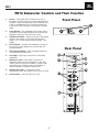
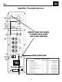
PB12 Subwoofer Controls and Their Function
1. Power - These lights will be red when the unit is
plugged in and not receiving a signal; when the PB12
receives a signal, the lights will cycle to GREEN. If no
signal is received after 10-15 minutes the lights will
cycle back to RED (standby) until a signal is present
again.
2. Level Control - The subwoofer Level Control, PB12,
(located on the rear panel) adjusts the volume of the
subwoofer relative to the rest of the system.
3. LFE/Normal Switch - Ordinarily placed in the Normal
position - but switch to LFE when playing Dolby
®
Digital, DTS
®
or other digital surround modes - see
page 9.
4. Phase Switch - Changes the subwoofer’s output to
be in phase or 180 degrees out of phase with the
program material.
5. Crossover Frequency - Sets the highest frequency
the subwoofer will reproduce.
6. Line Input - Main Input connection to subwoofer
(preferred).
7. Speaker In Jacks - Main Input connection to
subwoofer when line level, subwoofer, or pre-amp
output connectors are not available, or when a high
pass filter (set at 150Hz) to main loudspeakers is
desired through the Speaker Output Jacks.
8. Speaker Out Jacks - Connected to main
loudspeakers when the Speaker Input Jacks are used.
9. Power Switch - Turns the PB12 on or off.
Rear Panel
Front Panel
R

PB12
7
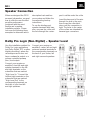
Speaker Connection
When we designed the PB12
powered subwoofers, our goal
was to offer the user the best
possible performance
combined with the most
flexible and complete
installation options. Please
look over the following three
examples to determine which
description best matches
your system and follow the
corresponding hookup
instructions.
To use the binding-post
speaker terminals with bare
wire, unscrew the collar until
the hole through the center-
post is visible under the collar.
Insert the bare end of the wire
through the hole in the post,
then screw the collar back
down until the connection is
tight. The holes in the center
of the collars are intended for
banana-type connectors.
Dolby Pro Logic (Non-Digital) – Speaker Level
Use this installation method for
Dolby Pro Logic applications
(not Dolby Digital, DTS or other
digital processing), where the
receiver/processor does not
have a subwoofer output or a
volume-controlled preamp
(line-) level output:
Connect your receiver or
amplifier’s front left and right
speaker terminals to the left
and right terminals on the
subwoofer that are marked
“High Level In.” Connect the
left and right terminals on the
subwoofer that are marked
“High Level Out” to the
corresponding terminals on
the back of your front left
and right speakers.
Connect your receiver or
amplifier’s center, left and right
surround-speaker terminals to
the corresponding terminals on
the back of your center, left
and right surround speakers.

PB12
8
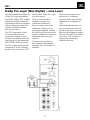
Dolby Pro Logic (Non-Digital) – Line Level
Use this installation method for
Dolby Pro Logic applications
(not Dolby Digital, DTS or other
digital processing), where the
receiver/processor is equipped
with a subwoofer output or a
volume-controlled preamp
(line-) level output:
Use RCA-type patch cords
to connect the line-level
subwoofer outputs on your
receiver or amplifier to the line-
level inputs on the subwoofer.
IMPORTANT: Make sure that
the LFE toggle switch on the
subwoofer is in the “Normal”
position. Do not use the “LFE”
position with Dolby Pro Logic-
only processors.
Note: If your receiver or
amplifier only has one
subwoofer output jack,
then you may connect the
subwoofer output on your
receiver/preamplifier to either
the left or right line-level input
on the subwoofer. It makes no
difference which jack you
choose.
Connect each speaker to
the corresponding speaker
terminals on your receiver or
amplifier.
Make sure your receiver or
processor is configured
cor
rectly: Make sure that the
sub
woofer is configured as
“On.”
Note for advanced users: If
your receiver/processor has
a built-in low-pass crossover
filter for the subwoofer output,
then the LFE switch should be
set to the “LFE” position to
bypass the subwoofer’s
internal crossover.

PB12
9
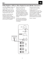
Dolby Digital or DTS (or Other Digital Surround Mode) Connection
Use this installation method for
Dolby Digital, DTS or other
digital surround processors:
IMPORTANT: Make sure that
the LFE toggle switch on the
subwoofer is in the “LFE”
position. Use the line-level
input jacks for the Low-
Frequency Effects channel.
Connect these jacks to the LFE
output or subwoofer output on
your receiver or amplifier.
Note: If your receiver or
amplifier only has one
subwoofer output jack,
then you may connect the
subwoofer output on your
receiver/preamplifier to either
the left or right line-level input
on the subwoofer. It makes no
difference which jack you
choose.
Connect each speaker to
the corresponding speaker
terminals on your receiver
or amplifier.
Make sure that you have
configured your surround-
sound processor for
“Subwoofer On” or “LFE On.”
The front left, front right, center
and rear speakers should be
set to “Small” or “Large”
depending on their size and
frequency response. Consult
your receiver’s or processor’s
owner’s manual.

PB12
10
OPERATION
Power
When the unit is plugged in
and the power switch is on and
no signal is received, the LEDs
on the front of the unit will turn
red. When a signal is present,
the LEDs will turn green.
Note: It will take several
minutes for the LEDs to turn
from green to red after the
input signal to the subwoofer is
removed. Due to JBL’s unique,
high-output,
high-efficiency
amplifier design, power
consumption is minimal when
the subwoofer is not receiving
a signal.
PowerBass PB12
CAUTION
RISK OF ELECTRIC SHOCK
DO NOT OPEN
120V
60Hz
CROSSOVER
FREQUENCY
LEVEL
LINE LEVEL IN
PHASE
Min
Max
L
R
L R
For LFE use L or R
LFE NORMAL
PowerBass PB12
HIGH
LEVEL
IN
L
R
HIGH
LEVEL
OUT
+ –
50Hz
0º 180º
150Hz
POWER
ON OFF
The subwoofer Level Control
adjusts the volume of the
subwoofer relative to the rest
of the system. Proper level
adjustments depend on several
variables such as room size,
subwoofer placement, type of
main speakers and listener
position. Adjust the subwoofer
level so that the volume of the
bass information is pleasing
to you.
Level Control
Crossover Adjustments
The Crossover Frequency
Control determines the highest
frequency at
which the
subwoofer reproduces
sounds.
If your main speakers can
comfortably reproduce some
low-frequency sounds, set this
control to a lower frequency
setting, between 50Hz – 100Hz.
This will concentrate the
subwoofer’s efforts on the
ultradeep bass sounds required
by today’s films and music. If
you are using smaller bookshelf
speakers that do not extend to
the lower bass frequencies, set
the low-pass crossover control
to a higher setting, between
120Hz – 150Hz. This control is
not used when the LFE switch
is in the “LFE” position.

PB12
11
Phase Control
The Phase Control determines
whether the subwoofer’s
piston-like action moves in and
out in phase with the main
speakers or opposite the main
speakers. There is no correct
or incorrect setting. Proper
phase adjustment depends on
several variables such as
subwoofer placement and
listener position. Adjust the
phase switch to maximize bass
output at the listening position.
Remember, every system,
room and listener is different.
There are no right or wrong
settings; this switch offers the
added flexibility to adjust your
subwoofer for optimum
performance for your specific
listening conditions without
having to move your speakers.
If at some time in the future
you happen to rearrange your
listening room and move
your speakers, you should
experiment with the phase
switch in both positions, and
leave it in the position that
maximizes bass performance.
TROUBLESHOOTING
If you used the high-level
(speaker) inputs and there
is no sound from any of the
speakers:
•
Check that receiver/amplifier
is on and a source is playing.
• Check that powered
subwoofer is plugged into
an active electrical outlet
and is switched on.
• Check all wires and
connections between
receiver/amplifier and
speakers. Make sure all wires
are connected. Make sure
none of the speaker wires are
frayed, cut or punctured.
• Review proper operation
of your receiver/amplifier.
If there is low (or no) bass
output:
• Make sure the connections to
the left and right “Speaker
Inputs” have the correct
polarity (+ and –).
• Make sure that the
subwoofer is plugged into an
active electrical outlet and
switched on.
• Adjust the crossover point.
• Flip the Phase Control switch
to the opposite position.
• If you are using a Dolby
Digital/DTS receiver or
processor, make sure that the
subwoofer adjustments on
the receiver/processor are
set up correctly.
• Slowly turn the Level
Control clockwise until you
begin to hear the desired
amount of bass.
If you used the line-level
inputs and there is no sound
from the subwoofer:
•
Check that receiver/amplifier
is on and a source is playing.
• Check that powered
subwoofer is plugged into an
active electrical outlet and is
switched on.
• Check all wires and
connections between
receiver/ amplifier and
subwoofer. Make sure all
wires are connected. Make
sure none of the wires are
frayed, cut or punctured.
• Review proper operation of
your receiver/amplifier.
• Slowly turn the Level
Control clockwise until you
begin to hear the desired
amount of bass.
• Make sure that you have
configured your receiver/
processor so that the
subwoofer/LFE output is on.

PB12
12
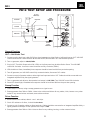
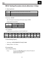
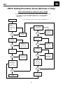
PB12 TEST SETUP AND PROCEDURE
Min Max
LEVEL
50 Hz 150 Hz
LFE
NORMAL
PHASE
180
0
CROSSOVER
FREQUENCY
LINE LEVEL IN
LR
FOR LFE USE L or R
L
HIGH
LIVEL
IN
R
L
HIGH
LIVEL
OUT
R
00229
CD PLAYER
PRE AMP
AMPLIFIER
AC VOLT
METER (6V)
LINE LEVEL
PB12
UNDER TEST
SPEAKER
LEVEL
FROM
LINE-LEVEL
SOURCE
SPEAKER
OUTPUT
FROM
AMPLIFIER
PowerBass PB12
General Function
UUT = Unit Under Test
1. Connect one line level input cable (RCA) from signal generator to either Right or Left Level input on UUT. VOLUME
control should be full conterclockwise. Make sure the LFE/Normal switch is in the NORMAL position.
2. Turn on generator, adjust to
100mV, 50Hz.
3. Plug in UUT; Turn Main Power switch ON. LED’s on the front panel may be either Red or Green. Turn VOLUME
control full clockwise. Low Pass control should be set fully clockwise (150Hz).
4. LED should turn Green; immediately bass response should be heard and felt from port tube opening.
5. Turn off generator, turn VOLUME control fully counterclockwise, disconnect RCA cables.
6. Connect one pair of speaker cables to either high level input terminal on UUT. Cables should be connected to an
integrated amplifier fed by the signal generator.
7. Turn on generator and adjust so that speaker level output is
1.0V, 50Hz. Turn VOLUME control full clockwise.
8. Green LED should light, immediate bass response should be heard and felt from the port tube opening.
Sweep Function
1. Follow steps 1-4 above, using a sweep generator as a signal source.
2. Sweep generator from 20Hz to 300Hz. Listen to the cabinet and drivers for any rattles, clicks, buzzes or any other
noises. If any unusual noises are heard, remove driver and test.
Driver Function
1. Remove driver from cabinet; detach + and – wire clips.
2. Check DC resistance of driver; it should be 4.8 ohms.
3. Connect a pair of speaker cables to driver terminals. Cables should be connected to an integrated amplifier fed by a
signal generator and adjust so that speaker level output is 5.0V.
4. Sweep generator from 20Hz to 1kHz. Listen to driver for any rubbing, buzzing, or other unusual noises.

PB12
13
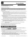
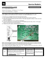
Service Bulletin
Service Bulletin JBL2001-03 Rev1 – January 2002 This is considered a Minor repair
To: All JBL Service Centers
Models: PB10, PB12 (Revision 1 only)*
Subject: Unit Will Not Switch to Standby Mode
When the power cord of the PB series subwoofer is plugged into a wall outlet (and for the PB12 only, the power
switch is on), and an audio signal is present, the LED’s on the cabinet face will turn green, indicating the
subwoofer is in the ON mode. With the audio signal removed, it will take 10 - 15 minutes for the LEDs to turn
from green to red, indicating the subwoofer is now in the STANDBY mode. Power consumption is minimal in this
mode.
In the event you receive a PB10 or PB12 subwoofer with the complaint: “The unit will not switch to
standby mode, even when the audio signal is removed” (indicated by the subwoofer’s green LED’s
remaining on), perform the following modification:
1) Set the unit on a padded surface and remove all external cables.
2) On the amplifier faceplate, remove the (10) Phillips mounting screws around the perimeter.
3) Remove the amplifier assembly from the enclosure. If the amp is turned and supported correctly, no other
connectors need to be unplugged.
4) Locate Zener Diode D10 and Resistor R42 (22kΩ). See illustration. These parts must be “swapped”, i.e.,
R42 soldered into the D10 location, and D10 soldered into the R42 location. VERY IMPORTANT: Observe
polarity on D10 in new location.
5) Replace amplifier; test subwoofer to assure the unit goes into the standby mode 10 - 15 minutes after
removing the Audio input signal.
Mode l S e r i al num be r S ta tus Ac ti on
PB10 *
PB12 *
Al l ser i al number s
af f ect ed
Unit may not switch to Standby mode
Swap locations:
Zener Diode D10,
Resistor R42 (22kΩ).
Observe D10 polarity.
* Revision 1 of the PB10/12: Amplifier faceplate says “Made in Canada”; Amplifier serial number starts with “AM”
Black (or silver) potted, non-serviceable S53/64AMI output module. PB10 only – No Power switch

JBL Incorporated 250 Crossways Park Dr. Woodbury, New York 11797 (516) 496-3400
Service Bulletin
Service Bulletin JBL2001-04 Rev2 – February 2003 This is considered a Minor repair
To: All JBL Service Centers
Models: PB10, PB12 (Revision 1 only)*
Subject: Hum, Buzz or “Thumping”
In the event you receive a PB10 or PB12 subwoofer complaint: “There is an audible hum or buzz”, or the
subwoofer “thumps” or “pops” every 10 seconds, then review the conditions below to determine the most
effective solution:
A) Audible Hum with unit on, Green LED is ON, hum disappears completely when the connecting input cables (RCA or
Speaker-Level) are disconnected:
Very long runs of line-level input cables, particularly in parallel with AC power cords, may induce hum in the
audio cables. Check audio cables for defects, broken ground connections, or replace low quality cables. Try
plugging the AC power cord from the subwoofer into a different AC service outlet other than the outlet the rest
of the audio equipment is plugged into.
B) Mild Audible Hum under all circumstances when power cord is plugged in outlet. Hum level does not change
whether the LED’s are Red or Green, or input cables are connected or disconnected. Level control adjustments do
not change the hum level.
This may be a mechanical hum caused by the power transformer. Note that a slight hum, within design limits,
may be noticeable in a very quiet room, when you are close to the unit. This is acceptable within the PB10/12’s
product and price category to most customers, but not to others. If the mechanical hum is unacceptable to the
customer, then replace Power Transformer. PB10: JBL part# 80135. PB12: JBL part# 80116
C) Loud Hum, under all circumstances. It may be louder when LED’s are Green vs. Red ; it may be affected by the
position of the Level control. The subwoofer may “thump” or “pop” approximately every 10 seconds.
Reset the digital subwoofer amplifier by unplugging the AC power cord. Wait 30 seconds, then plug the cord
back in. Repeat this 2-3 times if necessary.
For #B only - If the unit still does not function correctly, then check and replace main Power Supply
capacitors C1 and C2.
Both Value and df should be checked, with a GenRad model 1657 Digibridge or equivalent
Value should be the rating listed below, within this tolerance:
+80/-20 %
A df value of higher than 15% (.15) should be considered defective.
PB10
4700 µF 50v 105c
JBL part# 30706
PB12
2200 µF 100v 105c
JBL part# 30710
For #C only - If the unit still does not function correctly, then replace Power Amp Module S53/64AMI as per
instructions below: PB10: JBL part# 60301
PB12: JBL part# 60302
1) Set the unit on a padded surface and remove all external cables.
2) On the amplifier faceplate, remove the (10) Phillips mounting screws around the perimeter.
3) Remove the amplifier assembly from the enclosure. If the amp is supported correctly, no other connectors need to
be unplugged.
4) Locate the Power Amp Module S53/64AMI, see location on the following page. It is the large black or gray
component with a metal case. On the solder side of the circuit board are 28 soldered connections. NOTE: See
special handling instructions for S53/64AMI on the following page.
5) Replace the amplifier assembly back into the cabinet; replace the screws.
6) Test the unit and confirm the original problem has been corrected. NOTE: THE PB10/12 REVISION 1 AMPLIFIER
MUST ALWAYS BE TESTED WITH A WOOFER OR 4 OHM RESISTIVE LOAD.
14

JBL Incorporated 250 Crossways Park Dr. Woodbury, New York 11797 (516) 496-3400
PB10/12 Revision 1 Only
MODEL
Serial Number (120v)
Serial numbers are located on the cabinet directly below
the amplifier faceplate.
STATUS ACTION
PB10
See serial numbers on Page 3 for factory
modified units
Hum, Buzz or “Thumping”
Replace Power Amp Module S53AMI
for symptoms described in #C only
PB12 Hum, Buzz or “Thumping”
Replace Power Amp Module S64AMI
for symptoms described in #C only
* Revision 1 of the PB10/12: Amplifier faceplate says “Made in Canada”; Amplifier serial number starts with “AM”
Black (or silver) potted, non-serviceable S53/64AMI output module. PB10 only – No Power switch
15

JBL Incorporated 250 Crossways Park Dr. Woodbury, New York 11797 (516) 496-3400
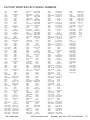
FACTORY MODIFIED PB-10 SERIAL NUMBERS
1953 23000
7720 23896
8579 23904-23905
10145 23989
10448 23991
10458 23993
11772 23997
11792 24004
11939 24010
13128 24166
13296 24230
14371 24874-24875
14508 24888
14510 24902
14519 24905-24907
14674 24909
14822 24913-24914
15092 24919
15525 24924
15634 24926
15644-15645 24928-24929
15649 24931-24932
15654 24934
15657 24936
15659 24939
15662 24944
15673-15674 24948
15676-15677 24950
15679 24960
15681 24986
15683 24988
15692 24991
15696 24994
15702 24996
15705 24998
16413 25001
17723 25003-25005
17740 25007
18274 25015
19665 25018
20470 25020
21026 25025
21124 25029-25030
21126 25033
21637 25037
22892 25039
22894-22895 25041
22901 25043-25056
22905-22906 25058-25115
22908 25117
22913 25119-25142
22917 25144-25147
22927 25149-25152
22933 25154-25156
25158-25159 25436
25161 25691
25164 25694
25168 25698-25699
25171 25704
25174 25706
25179 25710
25185 25712-25713
25187 25715-25719
25189 25721-25730
25194 25732
25214 25734
25218-25219 25735
25229 25737-25739
25234-25236 25742-25745
25238-25243 25747-25770
25247-25249 25772-25777
25251-25252 25779-25791
25256-25257 25793-25833
25261-25263 25835-25845
25265-25267 25847-25850
25270-25272 25852-25864
25276 25866-25868
25278-25291 25870
25294-25297 25874-25881
25300 25883-25886
25302-25303 25888
25306-25307 25890-25891
25309 25893-25894
25311 25896-26000
25313-25314 26002-26012
25333-25334 26014-26076
25341 26079
25345 26081
25347-25348 26083
25351-25352 26086-26087
25358 26089-26091
25360-25361 26093-26094
25363-25364 26096-26097
2536825369 26099-26101
25371 26103-26104
25375 26106
25384-25386 26108
25391-25392 26110
25394 26112
25396 26115
25399 26118-26119
25402 26121-26124
25406 26126
25408 26128
25416 26130-26131
25419 26133-26134
25421 26136-26137
25426 26139
26141-26150 26522
26152- 26172 26525
26174 26528
26176-26185 26531
26187-26197 26533
26198-26201 26536
26203 26540-26541
26206 26543-26544
26209 26546-26554
26211 26556-26557
26213-26214 26560
26217 26565
26235 26568
26238 26573
26242 26587
26244 26599
26246 26604
26251-26252 26614-26615
26254-26255 26624-26625
26266 26627
26273 26629
26278 26632
26282 26638
26286 26641-26643
26384 26645
26388 26655
26390-26391 26658
26399-26400 26662
26402 26665
26405-26406 26669
26408-26409 26671
26411 26673
26413-26415 26675-26677
26417 26680
26419 26686
26421 26692-26694
26432 26696-26697
26438-26439 26700
26443 26702
26451-26452 26706
26457-26458 26708
26460-26462 26713-26716
26465 26718-26720
26474 26722-26725
26477 26729-26730
26479-26480 26732-26743
26483 26745-26747
26486 26750
26498 26752-26753
26503 26755
26510-26512 26757-26759
26514 26762-26768
26517 26770-26771
26520 26773-26778
26781 27376-27399
26783 27401-27503
26786 27532
26789 27553
26791 27624-27647
26793 27649-27698
26795-26797 27701-27720
26799-26801 27722-27769
26804 27771-27774
26807 27776-27852
26810 27854-27866
26813 27868-27911
26815-26816 27913-27999
26820 28001-28067
26822 28069
26825 28070
26827 28072-28073
26829 28075
26833-26834 28078
26838 28087
26840 28092-28094
26843 28096-28097
26844 28099
26846 28101-28102
26850 28105
26857 28108
26874 28110-28114
26876-26880 28116-28117
26882 28119-28120
26885-26886 28122-28123
26888-26894 28125
26913 28130-28131
26915-26917 28133
26922-26935 28137
26967 28140-28150
26984-27001 28152-28158
27010-27033 28160-28161
27100 28167
27103-27104 28172
27122-27126 28177
27142-27143 28181
27148-27149 28184
27151 28186-28187
27153 28193
27190 28196
27192 28202-28203
27196-27273 28207
27275-27277 28211
27279-27312 28215
27314-27329 28217-28218
27331-27351 28220-28221
27353-27370 28223
27372 28227
27374 28231-28234
28236-28237 29792-29860
28239-28241 29862-29915
28243 29917-30062
28245 30064-30133
28250 30152-30288
28256 30290-30345
28259 30347-30413
28264-28267 30415-30490
28270-28271 30492-30524
28283 30526-30533
28286 30535-30625
28288 30627-30649
28291 30651-30686
28293-28294 30688-30748
28296 30750-30930
28298 30932-31025
28300 31027-31072
28302-28303 31074-31123
28305-28331 31125
28333-28343 31127-31139
28345-28354 31256
28369 31771
28379-28689 35089
28691-28697 35733
28699-28708 36186
28710-28715 37400
28717-28720 39339
28722-28724 80749
28726-28731
28734
28736
28738-28740
28742-28744
28746-28750
28752-28754
28756-28821
28823-29130
29132-29142
29144-29219
29221-29276
29278-29280
29282-29327
29329-29338
29340-29379
29381-29389
29391-29451
29453-29455
29457
29459-29528
29530-29531
29533-29605
29607-29624
29626-29634
29636-29790
16

17
Service Bulletin
Service Bulletin JBL2001-05 Rev2 - February 2002 This is considered a Minor repair
To: All JBL Service Centers
Models: PB12 (Revision 1 only)*
Subject: Popping Every Few Seconds During Play
In the event you receive a PB12 subwoofer with the complaint: “The subwoofer “thumps” or “pops”
every few seconds of play”, follow the procedure below:
Probable Cause:
Inductor L1 (220uH) may be damaged.
Check and Replace L1 if necessary:
1) Set the unit on a padded surface and remove all external cables.
2) On the amplifier faceplate, remove the (10) Phillips mounting screws around the perimeter.
3) Remove the amplifier assembly from the enclosure. If the amp is supported correctly, no other
connectors need to be unplugged.
4) Locate Inductor L1 on the main PCB. If the windings appear charred or burnt, it must be replaced.
5) Order JBL part# 80121 and replace L1.
6) Replace the amplifier assembly back into the cabinet; replace the screws.
7) Test the unit and confirm the original problem has been corrected.
Model Serial number (120V) Status Action
PB12 * AM0035-24318 and below L1 may be damaged
if experiencing above symptoms
Replace L1
with JBL part# 80121
PB12 * AM0035-24319 and above Modified by factory None required
* Revision 1 of the PB12: Amplifier faceplate says “Made in Canada”; Amplifier serial number starts with “AM”
Black (or silver) potted, non-serviceable S64AMI output module.

PB12
18
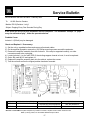
Service Bulletin
Service Bulletin JBL2001-07 Rev1 - February 2002 This is considered a Minor repair
To: All JBL Service Centers
Model: PB12 (Revision 1 only)*
Subject: Possible Missing Diode D4
In the event you receive a PB12 subwoofer for any servicing reason, check for the presence of
diode D4 on the Main PCB close to the Power Amp Module (see illustration). If D4 is missing or
has been “cut out” of the circuit, it should be replaced; add JBL part# 50115. Observe polarity.
Note: The presence or absence of D4, in itself, does not contribute to, or solve, an amplifer failure.
Purpose of D4 is to reduce the possibility of an occasional Turn-OFF pop noise.
Reference for general location only; all parts or designators may not conform exactly to this drawing.
* Revision 1 of the PB12:
Amplifier faceplate says “Made in Canada”; Amplifier serial number starts with “AM”
Black (or silver) potted, non-serviceable S64AMI output module.

Service Bulletin
Service Bulletin JBL2003-08 – July 2003 This is considered a Minor repair
To: All JBL Service Centers
Models: PB12 (Revision 2, PCB Revision “C” or “D” only) *
Subject: Service Modification – L5 Bypass
In the event you receive a PB12 subwoofer for servicing, the following modification should be performed
to the amplifier, after identification that it is Revision 2, and with PCB Revision “C” or “D”:
1) Set the unit on a padded surface and remove all external cables.
2) On the amplifier faceplate, remove the (10) Phillips mounting screws around the perimeter.
3)
Remove the amplifier assembly from the enclosure. If the amp is supported correctly, no other connectors
need to be unplugged.
4)
Remove the plastic rear cover to access the components.
5) Locate L5 Ferrite Bead; on the opposite side of the PCB (SMD component side), solder a 16-18 gauge
jumper or buss wire across its two connections.
6) Complete any other repairs; reassemble and test the unit.
NOTE: Some woofers that were used in the PB12 had similar terminals (both .205") so there is no polarity-keying if the
woofer wires are unplugged for any reason, (even though the amp output terminals themselves are dissimilar (.205 and
.250). In this case, assure the polarity is correct if the woofer wires have been unplugged.
Green = Positive (.250”), Black = Negative (.205”). The “+” and “-“ markings are on the woofer terminal block. Assure the
Faston connectors are tight and crimped on the terminals.
MODEL
* Identification of the PB12 Revision 2: (120v)
STATUS ACTION
PB12
1) Amplifier serial number starts with “HA”
Output transistors in the open, on a large black heatsink
Large plastic cup enclosing the rear of the amp assembly
Main PCB, bottom, solder-side contains all SMD devices
“Made in Mexico” label on outer part of cabinet
2) PCB Revision “C” and “D”
– Revision silkscreen can be
found on the long outer edge of the PCB
All PB12 amplifiers
Revision 2 and PCB
Revision “C” and “D”
should be modified during
any service procedure to
avoid Q18,Q22 damage
Solder a jumper or buss
wire across L5 to bypass it.
19

TECH TIPS
Troubleshooting tips and solutions to common service problems
For models: PB10, PB12 (Revision 2) * TIP# JBLTT2003-04
Subject: Replacing MOSFETS Q18, Q22
In the event you need to replace MOSFET transistors Q18 or Q22 as part of a repair, it is important to use
ONLY the JBL part# FE106401110 or only the brands: International Rectifier, or Fairchild.
Replace both
Q18 and Q22 MOSFET’s in the circuit, even if only one seems to be damaged.
Do NOT mix & match these components from different manufacturers, or batches. They should be
identical.
* Late version PB10 or PB12 subwoofers (Revision 2 in the service manual) can be identified by:
• Amplifier serial number starts with “HA”
• Output transistors in the open, on a large black heatsink
• Large plastic cup enclosing the rear of the amp assembly
• Main PCB, bottom, solder-side contains all SMD devices
20
Page is loading ...
Page is loading ...
Page is loading ...
Page is loading ...
Page is loading ...
Page is loading ...
Page is loading ...
Page is loading ...
Page is loading ...
Page is loading ...
Page is loading ...
Page is loading ...
Page is loading ...
Page is loading ...
Page is loading ...
Page is loading ...
Page is loading ...
Page is loading ...
Page is loading ...
Page is loading ...
Page is loading ...
Page is loading ...
Page is loading ...
Page is loading ...
Page is loading ...
Page is loading ...
Page is loading ...
Page is loading ...
Page is loading ...
Page is loading ...
Page is loading ...
Page is loading ...
Page is loading ...
Page is loading ...
Page is loading ...
Page is loading ...
Page is loading ...
-
 1
1
-
 2
2
-
 3
3
-
 4
4
-
 5
5
-
 6
6
-
 7
7
-
 8
8
-
 9
9
-
 10
10
-
 11
11
-
 12
12
-
 13
13
-
 14
14
-
 15
15
-
 16
16
-
 17
17
-
 18
18
-
 19
19
-
 20
20
-
 21
21
-
 22
22
-
 23
23
-
 24
24
-
 25
25
-
 26
26
-
 27
27
-
 28
28
-
 29
29
-
 30
30
-
 31
31
-
 32
32
-
 33
33
-
 34
34
-
 35
35
-
 36
36
-
 37
37
-
 38
38
-
 39
39
-
 40
40
-
 41
41
-
 42
42
-
 43
43
-
 44
44
-
 45
45
-
 46
46
-
 47
47
-
 48
48
-
 49
49
-
 50
50
-
 51
51
-
 52
52
-
 53
53
-
 54
54
-
 55
55
-
 56
56
-
 57
57


Ask a question and I''ll find the answer in the document
Finding information in a document is now easier with AI
Related papers
-
JBL PowerBass PB12 User manual
-
-
-
-
-
-
-
-
-
Other documents
-
KRAFTWERK 32018 User manual
-
Morel SUB-8 Owner's manual
-
AVLink AMP-25 Owner's manual
-
Cambridge SoundWorks Newton P500 User manual
-
 PYLE Audio PSL142X User manual
-
 Pinnacle Speakers PIN AMP 800 User manual
-
Infinity BU-150 User manual
-
 PYLE Audio PSL212X User manual
-
SV Sound PB12-NSD User manual
-


