Page is loading ...

17291 Mt. Herrmann Street
Fountain Valley, CA 92708
Printed in Taiwan
Instruction MRP
Copyright © 2008 IEC. All Rights Reserved.
#93-0099 Rev. C

Table of Contents
i OBD2
INTRODUCTION
WHAT IS OBD?
..................................................................................... 1
YOU CAN DO IT! ............................................................................................ 2
SAFETY PRECAUTIONS
SAFETY FIRST!
..................................................................................... 3
ABOUT THE SCAN TOOL
VEHICLES COVERED
......................................................................... 5
BATTERY REPLACEMENT ............................................................... 6
ADJUSTMENTS AND SETTINGS .................................................... 7
SCAN TOOL CONTROLS
CONTROLS AND INDICATORS
...................................................... 11
DISPLAY FUNCTIONS ........................................................................ 12
ONBOARD DIAGNOSTICS
DIAGNOSTIC TROUBLE CODES (DTCs)
..................................... 15
PREPARATION FOR TESTING
PRELIMINARY VEHICLE DIAGNOSTIC WORKSHEET
........... 17
BEFORE YOU BEGIN ......................................................................... 20
VEHICLE SERVICE MANUALS ........................................................ 21
USING THE SCAN TOOL
CODE RETRIEVAL PROCEDURE
.................................................. 22
THE ENHANCED MAIN MENU ......................................................... 28
VIEWING ABS DTCs ............................................................................ 29
VIEWING ENHANCED DTCs ............................................................ 32
ERASING DIAGNOSTIC TROUBLE CODES (DTCs)................. 40
I/M READINESS TESTING ................................................................ 41
LIVE DATA MODE
VIEWING LIVE DATA
.......................................................................... 47
CUSTOMIZING LIVE DATA (PIDs) .................................................. 48
RECORDING (CAPTURING) LIVE DATA ..................................... 49
LIVE DATA PLAYBACK ...................................................................... 53
O2 SENSOR TEST ............................................................................... 55
NON-CONTINUOUS TEST ................................................................ 57
SYSTEM TEST ...................................................................................... 58
VEHICLE INFORMATION ................................................................... 59
GENERIC (GLOBAL) OBD2 PID LIST ..................................................... 61
GLOSSARY
GLOSSARY OF TERMS AND ABBREVIATIONS
....................... 66
WARRANTY AND SERVICING
LIMITED ONE YEAR WARRANTY
.................................................. 69
SERVICE PROCEDURES .................................................................. 69

Introduction
WHAT IS OBD?
OBD2 1
WHAT IS OBD?
The Enhanced OBD2 Scan Tool is designed to work on all OBD2
compliant vehicles. All 1996 and newer vehicles (cars, light trucks
and SUVs) sold in the United States are OBD2 compliant.
One of the most exciting improvements in the
automobile industry was the addition of on-
board diagnostics (OBD) on vehicles, or in more
basic terms, the computer that activates the
vehicle’s “CHECK ENGINE” light. OBD1 was
designed to monitor manufacturer-specific
systems on vehicles built from 1981 to 1995.
Then came the development of OBD2, which is
on all 1996 cars and light trucks sold in the U.S. Like its predecessor,
OBD2 was adopted as part of a government mandate to lower vehicle
emissions. But what makes OBD2 unique is its universal application for
all late model cars and trucks - domestic and import. This sophisticated
program in the vehicle’s main computer system is designed to detect
failures in a range of systems, and can be accessed through a universal
OBD2 port, which is usually found under the dashboard. For all OBD
systems, if a problem is found, the computer turns on the “CHECK
ENGINE” light to warn the driver, and sets a Diagnostic Trouble Code
(DTC) to identify where the problem occurred. A special diagnostic tool,
such as the Enhanced OBD2 Scan Tool, is required to retrieve these
codes, which consumers and professionals use as a starting point for
repairs.
The Enhanced OBD2 Scan Tool provides the additional ability to
retrieve enhanced DTCs from most Chrysler/Jeep, General Motors,
Ford, Mazda and Isuzu vehicles. The types of enhanced data available
depends on the vehicle make. Chrysler/Jeep, Ford/Mazda, GM/Izusu,
Honda/Acura and Toyota/Lexus vehicles, as well as Anti-Lock Brake
System (ABS) DTCs and vehicle information. The types of enhanced
data available depends on the vehicle make.

You Can Do It!
EASY TO USE - EASY TO VIEW - EASY TO DEFINE
2 OBD2
Easy To Use . . . .
Connect the Scan Tool to the vehicle’s
test connector.
Turn the ignition key "On.”
Press the LINK button.
Easy To View . . . .
The Scan Tool retrieves stored codes,
Freeze Frame data and I/M Readiness
status.
Codes, I/M Readiness status and
Freeze Frame data are displayed on the
Scan Tool’s display screen. System
status is indicated by LED indicators.
Easy To Define . . . .
Read code definitions from the Scan
Tool’s display.
View Freeze Frame data.
View Live Data.

Safety Precautions
SAFETY FIRST!
OBD2 3
SAFETY FIRST!
This manual describes common test procedures used
by experienced service technicians. Many test procedures
require precautions to avoid accidents that can result in
personal injury, and/or damage to your vehicle or test
equipment. Always read your vehicle's service manual and
follow its safety precautions before and during any test or
service procedure. ALWAYS observe the following general
safety precautions:
When an engine is running, it produces carbon monoxide,
a toxic and poisonous gas. To prevent serious injury or
death from carbon monoxide poisoning, operate the
vehicle ONLY in a well-ventilated area.
To protect your eyes from propelled objects as well as hot
or caustic liquids, always wear approved safety eye
protection.
When an engine is running, many parts (such as the
coolant fan, pulleys, fan belt etc.) turn at high speed. To
avoid serious injury, always be aware of moving parts.
Keep a safe distance from these parts as well as other
potentially moving objects.
Engine parts become very hot when the engine is running.
To prevent severe burns, avoid contact with hot engine
parts.
Before starting an engine for testing or troubleshooting,
make sure the parking brake is engaged. Put the
transmission in park (for automatic transmission) or
neutral (for manual transmission). Block the drive wheels
with suitable blocks.
Connecting or disconnecting test equipment when the
ignition is ON can damage test equipment and the
vehicle's electronic components. Turn the ignition OFF
before connecting the Scan Tool to or disconnecting the
Scan Tool from the vehicle’s Data Link Connector (DLC).
To avoid pe
r
sonal injury, instrument damage and/or
damage to your vehicle; do not use the OBD2 Scan Tool
before reading this manual.
N
L
D
R
P

Safety Precautions
SAFETY FIRST!
4 OBD2
To prevent damage to the on-board computer when taking
vehicle electrical measurements, always use a digital
multimeter with at least 10 megOhms of impedance.
Fuel and battery vapors are highly flammable. To prevent
an explosion, keep all sparks, heated items and open
flames away from the battery and fuel / fuel vapors. DO
NOT SMOKE NEAR THE VEHICLE DURING TESTING.
Don't wear loose clothing or jewelry when working on an
engine. Loose clothing can become caught in the fan,
pulleys, belts, etc. Jewelry is highly conductive, and can
cause a severe burn if it makes contact between a power
source and ground.

About the Scan Tool
VEHICLES COVERED
OBD2 5
VEHICLE EMISSION CONTROL INFORMATION
VEHICLE
MANUFACTURER
OBD II
CERTIFIED
ENGINE FAMILY EFN2.6YBT2BA
DISPLACEMENT 2.6L
THIS VEHICLE CONFORMS TO U.S. EPA AND STATE
OF CALIFORNIA REGULATIONS APPLICABLE TO
1999 MODEL YEAR NEW TLEV PASSENGER CARS.
REFER TO SERVICE MANUAL FOR ADDITIONAL INFORMATION
TUNE-UP CONDITIONS: NORMAL OPERATING ENGINE TEMPERATURE,
ACCESSORIES OFF, COOLING FAN OFF, TRANSMISSION IN NEUTRAL
SPARK PLUG
TYPE NGK BPRE-11
GAP: 1.1MM
CATALYST
EXHAUST EMISSIONS STANDARDS STANDARD CATEGORY
CERTIFICATION
IN-USE
TLEV
TLEV INTERMEDIATE
OBD II
CERTIFIED
VEHICLES COVERED
The Enhanced OBD2 Scan Tool is designed to work on all OBD2
compliant vehicles. All 1996 and newer vehicles (cars and light trucks)
sold in the United States are OBD2 compliant.
Federal law requires that all 1996 and newer cars and light
trucks sold in the United States must be OBD2 compliant; this
includes all Domestic, Asian and European vehicles.
Some 1994 and 1995 vehicles are OBD2 compliant. To find out if a
1994 or 1995 vehicle is OBD2 compliant, check the following:
1. The Vehicle Emissions Control Information (VECI) Label. This
label is located under the hood or by the radiator of most vehicles. If
the vehicle is OBD2 compliant, the label will state “OBD II
Certified.”
2. Government Regulations require that all
OBD2 compliant vehicles must have a
“common” sixteen-pin Data Link
Connector (DLC).
Some 1994 and 1995 vehicles have 16-pin connectors but are
not OBD2 compliant. Only those vehicles with a Vehicle
Emissions Control Label stating “OBD II Certified” are OBD2
compliant.
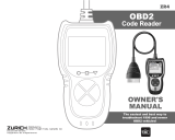
Data Link Connector (DLC) Location
The 16-pin DLC is usually
located under the instrument
panel (dash), within 12 inches
(300 mm) of center of the panel,
on the driver’s side of most
vehicles. It should be easily
accessible and visible from a
kneeling position outside the
vehicle with the door open.
12345678
9 10111213141516
NEAR
CENTER
OF DASH
BEHIND
ASHTRAY
LEFT CORNER
OF DASH

About the Scan Tool
BATTERY REPLACEMENT
6 OBD2
On some Asian and European vehicles the DLC is located
behind the “ashtray” (the ashtray must be removed to
access it) or on the far left corner of the dash. If the DLC
cannot be located, consult the vehicle’s service manual for
the location.
BATTERY REPLACEMENT
Replace batteries when the battery symbol is visible on display
and/or the 3 LEDS are all lit and no other data is visible on screen.
1. Locate the battery cover on the back of the Scan Tool.
2. Slide the battery cover off (use your fingers).
3. Replace batteries with three AA-size batteries (for longer life, use
Alkaline-type batteries).
4. Reinstall the battery cover on the back of the Scan Tool.
Language Selection After Battery Installation
The first time the Scan Tool is turned on, you must select the desired
display language (English, French or Spanish). Select the display
language as follows:
1. Press and hold the POWER/LINK
button for approximately 3 seconds to
turn the Scan Tool “ON.”
The Select Language screen dis-
plays.
2. Use the UP
and DOWN buttons,
as necessary, to highlight the desired
display language.
3. When the desired display language is selected, press the
ENTER/LD
button to confirm your selection.
The display shows the "To Link" message in the selected display
language. Press the POWER/LINK
button to turn the Scan
Tool "off."
After the initial language selection is performed, it as well as
other settings can be changed as desired. See ADJUSTMENTS
AND SETTINGS on page 7 for further instructions.

About the Scan Tool
ADJUSTMENTS AND SETTINGS
OBD2 7
ADJUSTMENTS AND SETTINGS
The OBD2 Scan Tool lets you make several adjustments and settings to
configure the Scan Tool for your particular needs. The following
adjustments and settings are available:
Adjust Brightness: Adjusts the brightness of the display screen.
DTC Library - Library of OBD2 DTC definitions.
Display Backlight: Turns the display backlight on and off.
Select Language: Sets the display language for the Scan Tool to
English, French or Spanish.
Unit of Measurement: Sets the Unit of Measurement for the Scan
Tool’s display to USA or metric.
Adjustments and settings can be made only when the Scan
Tool is NOT connected to a vehicle.
To enter the MENU Mode:
1. With the Scan Tool “off”, press and hold
the UP
button, then press and
release the POWER/LINK
button.
The adjustments and setting MENU
displays.
2. Release the UP
button.
DO NOT release the UP
button until the adjustments and
settings MENU is visible on the display.
3. Make adjustments and settings as described in the following
paragraphs.
Adjusting Display Brightness
1. Use the UP
and DOWN buttons,
as necessary, to highlight Adjust
Brightness in the MENU, then press
the ENTER/LD
button.
The Adjust Brightness screen
displays.
The Brightness field shows the
current brightness setting, from 0 to
43.
2. Press the UP
button to decrease the
brightness of the display (make the
display darker).

About the Scan Tool
ADJUSTMENTS AND SETTINGS
8 OBD2
3. Press the DOWN button to increase the brightness of the display
(make the display lighter).
4. When the desired brightness is obtained, press the ENTER/LD
button to save your changes and return to the MENU.
Searching for a DTC Definition Using the DTC Library
1. Use the UP
and DOWN buttons,
as necessary, to highlight DTC Library
in the MENU, then press the ENTER/LD
button.
The Enter DTC screen displays. The
screen shows the code “P0001”,
with the “P” flashing.
2. Use the UP
and DOWN buttons,
as necessary, to scroll to the desired
DTC type (P=Powertrain, U=Network,
B=Body, C=Chassis), then press the
DTC SCROLL
button.
The selected character displays “solid”,
and the next character begins flashing.
3. Select the remaining characters in the DTC in the same way,
pressing the DTC SCROLL button to confirm each character.
When you have selected all the DTC characters, press the
ENTER/LD
button to view the DTC definition.
If you entered a “Generic” DTC
(DTCs that start with “P0”, “P2” and
some “P3”):
- The selected DTC and DTC
definition (if available) show on
the Scan Tool’s display.
If a definition for the DTC you
entered is not available, the “To
Link” screen displays.
If you entered a “Manufacturer-Specific” DTC (DTCs that start
with “P1” and some “P3”):
- The “Select Manufacturer” screen
displays.
- Use the UP
and DOWN
buttons, as necessary, to high-
light the appropriate manufacturer,
then press the ENTER/LD
button to display the correct DTC
for your vehicle.

About the Scan Tool
ADJUSTMENTS AND SETTINGS
OBD2 9
If a definition for the DTC you
entered is not available, an
advisory message shows on the
CanOBD2 Scan Tool’s display.
4. If you wish to view definitions for
additional DTCs, press the ENTER/LD
button to return to the Enter DTC
screen, and repeat steps 2 and 3.
5. When all desired DTCs have been viewed, press the ERASE
button to exit the DTC Library.
Using the Backlight
1. Use the UP
and DOWN buttons,
as necessary, to highlight Display
Backlight in the MENU, then press the
ENTER/LD
button.
The Display Backlight screen dis-
plays.
2. Press the UP
or DOWN button,
as necessary, to select the desired
backlight mode, either ON or OFF.
3. When the desired backlight mode is
selected, press the ENTER/LD
button to save your changes.
The display returns to the MENU,
and the backlight turns “on” or “off”
as selected.
Selecting the Display Language
1. Use the UP
and DOWN buttons,
as necessary, to highlight Select
Language in the MENU, then press the
ENTER/LD button.
The Select Language screen dis-
plays.
The currently selected display
Language is highlighted.
2. Press the UP
or DOWN button,
as necessary, to highlight the desired
display language.
3. When the desired display language is
highlighted, press the ENTER/LD
button to save your changes and return
to the MENU (shown in the selected
display language).

About the Scan Tool
ADJUSTMENTS AND SETTINGS
10 OBD2
Setting the Unit of Measurement
1. Use the UP
and DOWN buttons,
as necessary, to highlight Unit of
Measurement in the MENU, then press
the ENTER/LD
button.
2. Press the UP
or DOWN button,
as necessary, to highlight the desired
Unit of Measurement.
3. When the desired Unit of Measurement
value is selected, press the ENTER/LD
button to save your changes.
Exiting the MENU Mode
1. Use the UP
and DOWN buttons, as necessary, to highlight
Menu Exit in the MENU, then press the ENTER/LD
button.
The display returns to the DTC screen (if data is currently stored
in the Scan Tool) or to the "To Link" message (if no data is
currently stored in the Scan Tool).

Scan Tool Controls
CONTROLS AND INDICATORS
OBD2 11
CONTROLS AND INDICATORS
Figure 1. Controls and Indicators
See Figure 1 for the locations of items 1 through 11, below.
1.
ERASE button - Erases Diagnostic Trouble Codes (DTCs), and
“Freeze Frame” data from your vehicle’s computer, and resets
Monitor status.
2.
DTC SCROLL button - Displays the DTC View screen and/or
scrolls the display to view DTCs when more than one DTC is
present.
3.
POWER/LINK button - When the Scan Tool IS NOT connected
to a vehicle, turns the Scan Tool “On” and “Off”. When the Scan
Tool is connected to a vehicle, links the Scan Tool to the vehicle’s
PCM to retrieve diagnostic data from the computer’s memory.
To turn the Scan Tool "On", you must press and hold the
POWER/LINK
button for approximately 3 seconds.
4.
ENTER/LIVE DATA button - When in MENU mode, confirms
the selected option or value. When linked to a vehicle, places the
Scan Tool in "Live Data" mode.
1
6
7
2
5
3
9
8
4
10
11

Scan Tool Controls
DISPLAY FUNCTIONS
12 OBD2
5. DOWN button - When in MENU mode, scrolls DOWN through
the menu and submenu selection options. When LINKED to a
vehicle, scrolls DOWN through the current display screen to display
any additional data.
6.
UP button - When in MENU mode, scrolls UP through the menu
and submenu selection options. When LINKED to a vehicle, scrolls
UP through the current display screen to display any additional data.
7. GREEN LED - Indicates that all engine systems are running
normally (all Monitors on the vehicle are active and performing their
diagnostic testing, and no DTCs are present).
8. YELLOW LED - Indicates there is a possible problem. A “Pending”
DTC is present and/or some of the vehicle’s emission monitors have
not run their diagnostic testing.
9. RED LED - Indicates there is a problem in one or more of the
vehicle’s systems. The red LED is also used to show that DTC(s)
are present. DTCs are shown on the Scan Tool’s display. In this
case, the Multifunction Indicator (“Check Engine”) lamp on the
vehicle’s instrument panel will light steady on.
10. Display - Displays settings Menu and submenus, test results, Scan
Tool functions and Monitor status information. See DISPLAY
FUNCTIONS, following, for more details.
11. CABLE - Connects the Scan Tool to the vehicle’s Data Link
Connector (DLC).
DISPLAY FUNCTIONS
Figure 2. Display Functions
See Figure 2 for the locations of items 1 through 16, following.
1. I/M MONITOR STATUS field - Identifies the I/M Monitor status area.
4
3
21
11
12 13
5
8
9
10
14
16
15
6
7

Scan Tool Controls
DISPLAY FUNCTIONS
OBD2 13
2. Monitor icons - Indicate which Monitors are supported by the
vehicle under test, and whether or not the associated Monitor has
run its diagnostic testing (Monitor status). When a Monitor icon is
solid, it indicates that the associated Monitor has completed its
diagnostic testing. When a Monitor icon is flashing, it indicates that
the vehicle supports the associated Monitor, but the Monitor has not
yet run its diagnostic testing.
3.
Vehicle icon - Indicates whether or not the Scan Tool is being
properly powered through the vehicle’s Data Link Connector (DLC).
A visible icon indicates that the Scan Tool is being powered through
the vehicle’s DLC connector.
4.
Link icon - Indicates whether or not the Scan Tool is
communicating (linked) with the vehicle’s on-board computer. When
visible, the Scan Tool is communicating with the computer. If the
Link icon is not visible, the Scan Tool is not communicating with the
computer.
5.
Computer icon - When this icon is visible it indicates that the
Scan Tool is linked to a personal computer. An optional “PC Link
Kit” is available that makes it possible to upload retrieved data to a
personal computer.
6.
Scan Tool Internal Battery icon - When visible, indicates the
Scan Tool batteries are “low” and should be replaced. If the
batteries are not replaced when the battery symbol
is "on", all 3
LEDs will light up as a last resort indicator to warn you that the
batteries need replacement. No data will be displayed on screen
when all 3 LEDs are lit.
7. DTC Display Area - Displays the Diagnostic Trouble Code (DTC)
number. Each fault is assigned a code number that is specific to that
fault.
8. Test Data Display Area - Displays DTC definitions, Freeze Frame
data, Live Data and other pertinent test information messages.
9. FREEZE FRAME icon - Indicates that there is Freeze Frame data
from “Priority Code” (Code #1) stored in the vehicle’s computer
memory.
10. HISTORY icon - Indicates the currently displayed DTC is a “History”
code.
11. PENDING icon - Indicates the currently displayed DTC is a
“Pending” code.
12. MIL icon - Indicates the status of the Malfunction Indicator Lamp
(MIL). The MIL icon is visible only when a DTC has commanded the
MIL on the vehicle’s dashboard to light.
13. Code Number Sequence - The Scan Tool assigns a sequence
number to each DTC that is present in the computer’s memory,
starting with “01.” This number indicates which code is currently
displayed. Code number “01” is always the highest priority code,
and the one for which “Freeze Frame” data has been stored.

Scan Tool Controls
DISPLAY FUNCTIONS
14 OBD2
If “01” is a “Pending” code, there may or may not be “Freeze
Frame” data stored in memory.
14. Code Enumerator - Indicates the total number of codes retrieved
from the vehicle’s computer.
15.
Generic DTC icon - When visible, indicates that the currently
displayed DTC is a “generic” or universal code.
16.
Manufacturer Specific DTC icon - When visible, indicates that
the currently displayed DTC is a Manufacturer Specific Code.

Onboard Diagnostics
DIAGNOSTIC TROUBLE CODES (DTCs)
OBD2 15
Diagnostic Trouble
Codes (DTCs) are
codes that identify a
specific problem area.
DIAGNOSTIC TROUBLE CODES (DTCs)
Diagnostic Trouble Codes (DTCs) are
meant to guide you to the proper
service procedure in the vehicle’s
service manual. DO NOT replace parts
based only on DTCs without first
consulting the vehicle’s service manual
for proper testing procedures for that
particular system, circuit or component.
DTCs are alphanumeric codes that are used to identify a
problem that is present in any of the systems that are
monitored by the on-board computer (PCM). Each trouble
code has an assigned message that identifies the circuit,
component or system area where the problem was found.
OBD2 diagnostic trouble codes are made up of five characters:
The 1st character is a letter. It identifies the “main system” where
the fault occurred (Body, Chassis, Powertrain, or Network).
The 2nd character is a numeric digit. It identifies the “type” of code
(Generic or Manufacturer-Specific).
Generic DTCs are codes that are used by all vehicle
manufacturers. The standards for generic DTCs, as well as
their definitions, are set by the Society of Automotive
Engineers (SAE).
Manufacturer-Specific DTCs are codes that are controlled by
the vehicle manufacturers. The Federal Government does not
require vehicle manufacturers to go beyond the standardized
generic DTCs in order to comply with the new OBD2
emissions standards. However, manufacturers are free to
expand beyond the standardized codes to make their systems
easier to diagnose.
The 3rd character is a numeric digit. It identifies the specific
system or sub-system where the problem is located.
The 4th and 5th characters are numeric digits. They identify the
section of the system that is malfunctioning.
DTCs and MIL Status
When the vehicle’s on-board computer detects
a failure in an emissions-related component or
system, the computer’s internal diagnostic
program assigns a diagnostic trouble code
(DTC) that points to the system (and subsystem)
where the fault was found. The diagnostic
program saves the code in the computer’s
memory. It records a “Freeze Frame” of
conditions present when the fault was found, and lights the Malfunction
Indicator Lamp (MIL). Some faults require detection for two trips in a row
before the MIL is turned on.

Onboard Diagnostics
DIAGNOSTIC TROUBLE CODES (DTCs)
16 OBD2
The “Malfunction Indicator Lamp” (MIL) is the accepted term
used to describe the lamp on the dashboard that lights to warn
the driver that an emissions-related fault has been found.
Some manufacturers may still call this lamp a “Check Engine”
or “Service Engine Soon” light.
P 0 2 0 1
B
C
P
U
-
-
-
-
Body
Chassis
Powertrain
Network
-
-
-
-
Generic
Manufacturer Specific
Generic
Includes both Generic and Manufacturer
Specific Codes
0
1
2
3
Identifies what section of the system
is malfunctioning
Identifies the system where the
problem is located:
1
2
3
4
5
6
7
8
-
-
-
-
-
-
-
-
Fuel and Air Metering
Fuel and Air Metering (injector circuit
malfunction only)
Ignition System or Misfire
Auxiliary Emission Control System
Vehicle Speed Control and Idle Control
System
Computer Output Circuits
Transmission
Transmission
OBD2 DTC EXAMPLE
P0201 - Injector Circuit Malfunction, Cylinder 1

Preparation for Testing
PRELIMINARY VEHICLE DIAGNOSTIC WORKSHEET
OBD2 17
PRELIMINARY VEHICLE DIAGNOSTIC WORKSHEET
The purpose of this form is to help you gather preliminary information on
your vehicle before you retrieve codes. By having a complete account of
your vehicle's current problem(s), you will be able to systematically
pinpoint the problem(s) by comparing your answers to the fault codes
you retrieve. You can also provide this information to your mechanic to
assist in diagnosis and help avoid costly and unnecessary repairs. It is
important for you to complete this form to help you and/or your
mechanic have a clear understanding of your vehicle's problems.
NAME:
DATE:
VIN*:
YEAR:
MAKE:
MODEL:
ENGINE SIZE:
VEHICLE MILEAGE:
*VIN: Vehicle Identification Number, found at the base of the windshield
on a metallic plate, or at the driver door latch area (consult your vehicle
owner's manual for location).
TRANSMISSION:
❏ Automatic
❏ Manual
Please check all applicable items in each category.
DESCRIBE THE PROBLEM:

Preparation for Testing
PRELIMINARY VEHICLE DIAGNOSTIC WORKSHEET
18 OBD2
WHEN DID YOU FIRST NOTICE THE PROBLEM:
❏ Just Started
❏ Started Last Week
❏ Started Last Month
❏ Other:
m
LIST ANY REPAIRS DONE IN THE PAST SIX MONTHS:
PROBLEMS STARTING
❏ No symptoms
❏ Will not crank
❏ Cranks, but will not start
❏ Starts, but takes a long
time
ENGINE QUITS OR STALLS
❏ No symptoms
❏ Right after starting
❏ When shifting into gear
❏ During steady-speed
driving
❏ Right after vehicle
comes to a stop
❏ While idling
❏ During acceleration
❏ When parking
IDLING CONDITIONS
❏ No symptoms
❏ Is too slow at all times
❏ Is too fast
❏ Is sometimes too fast or
too slow
❏ Is rough or uneven
❏ Fluctuates up and down
RUNNING CONDITIONS
❏ No symptoms
❏ Runs rough
❏ Lacks power
❏ Bucks and jerks
❏ Poor fuel economy
❏ Hesitates or stumbles on
accelerations
❏ Backfires
❏ Misfires or cuts out
❏ Engine knocks, pings or
rattles
❏ Surges
❏ Dieseling or run-on
/