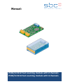
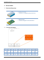
The SBC PCD2/3.H112/H114 modules are fast counting modules that offer a range of features for precise and efficient counting applications. With two or four channels, these modules can handle counting tasks up to 150 kHz. The modules provide two inputs (A and B) for each counter, enabling the determination of the direction of rotation of incremental shaft encoders. A configurable input C per counter allows for additional control options. With a counting range of 0 to 16,777,215, these modules can accommodate a wide range of counting requirements.
The SBC PCD2/3.H112/H114 modules are fast counting modules that offer a range of features for precise and efficient counting applications. With two or four channels, these modules can handle counting tasks up to 150 kHz. The modules provide two inputs (A and B) for each counter, enabling the determination of the direction of rotation of incremental shaft encoders. A configurable input C per counter allows for additional control options. With a counting range of 0 to 16,777,215, these modules can accommodate a wide range of counting requirements.


-
 1
1
-
 2
2
-
 3
3
-
 4
4
-
 5
5
-
 6
6
-
 7
7
-
 8
8
-
 9
9
-
 10
10
-
 11
11
-
 12
12
-
 13
13
-
 14
14
-
 15
15
-
 16
16
-
 17
17
-
 18
18
-
 19
19
-
 20
20
-
 21
21
-
 22
22
-
 23
23


The SBC PCD2/3.H112/H114 modules are fast counting modules that offer a range of features for precise and efficient counting applications. With two or four channels, these modules can handle counting tasks up to 150 kHz. The modules provide two inputs (A and B) for each counter, enabling the determination of the direction of rotation of incremental shaft encoders. A configurable input C per counter allows for additional control options. With a counting range of 0 to 16,777,215, these modules can accommodate a wide range of counting requirements.
Ask a question and I''ll find the answer in the document
Finding information in a document is now easier with AI
Related papers
-
SBC IO-Modules Owner's manual
-
-
-
-
-
-
-
-
-
Other documents
-
Samsung A400 User manual
-
iO HVAC Controls iO-WRP-B User manual
-
CyberResearch STH 15B Series User manual
-
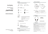 Jumper AngelSounds JPD-100S User manual
-
Iadea PRB-101 User guide
-
-
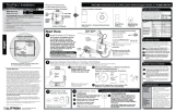 Lutron Electronics PowPak RMK-CCO1-24-B Installation guide
-
A.O. Smith Custom Commercial Solar Water Heating Systems Technical Documents

