Page is loading ...

DOTX-45
Dissolved Oxygen Transmitter


DOTX-45 - 2 -
Table of Contents
PART 1 - INTRODUCTION ............................................................................................................................... 4
1.1 General ................................................................................................................................................... 4
1.2 Standard System ..................................................................................................................................... 4
1.3 Features .................................................................................................................................................. 4
1.4 System Specifications ............................................................................................................................. 6
1.5 Performance Specifications ..................................................................................................................... 8
PART 2 – ANALYZER MOUNTING ................................................................................................................. 9
2.1 General ................................................................................................................................................... 9
Figure 2-1 Enclosure Dimensions, AC Powered Units ............................................................................. 10
Figure 2-2 Enclosure Dimensions, 2-Wire Units ...................................................................................... 11
2.2 Wall or Pipe Mount ............................................................................................................................... 12
Figure 2-3 Wall or Pipe mount Bracket.................................................................................................... 12
Figure 2-4 Wall Mounting Diagram ........................................................................................................ 13
Figure 2-5 Pipe Mounting Diagram ......................................................................................................... 13
2.4 Panel Mount, AC Powered Monitor ....................................................................................................... 14
Figure 2-6 115/230 VAC Panel Mount and Cut-out ................................................................................. 14
PART 3 – SENSOR MOUNTING ..................................................................................................................... 15
3.1 General ................................................................................................................................................. 15
3.2 Submersion Mounting ........................................................................................................................... 15
PART 4 – ELECTRICAL INSTALLATION .................................................................................................... 16
4.1 General ................................................................................................................................................. 16
4.2 Two-Wire ............................................................................................................................................. 16
Figure 4-1 Loop-Power Connection ........................................................................................................ 17
Figure 4-2 Submersible Sensor Connection ............................................................................................ 18
4.21 Load Drive ........................................................................................................................................ 18
4.3 115 VAC w/Relays ............................................................................................................................... 19
Figure 4-3 Line Power Connection .......................................................................................................... 20
Figure 4-4 Relay Contacts ...................................................................................................................... 21
4.4 Sensor Wiring ....................................................................................................................................... 21
4.5 Direct Sensor Connection ...................................................................................................................... 21
Figure 4-5 Sensor Cable Preparation....................................................................................................... 22
PART 5 – SENSOR ASSEMBLY ...................................................................................................................... 23
5.1 Oxygen Sensor Preparation ................................................................................................................... 23
Figure 5-1 Submersible Oxygen Sensor Assembly .................................................................................. 23
Figure 5-2 Submersible Sensing Module Assembly ................................................................................ 24
PART 6 – CONFIGURATION .......................................................................................................................... 26
6.1 User Interface ....................................................................................................................................... 26
Figure 6-1 User Interface........................................................................................................................ 26
6.11 Keys ................................................................................................................................................. 27
6.12 Display ............................................................................................................................................. 27
6.2 Software ............................................................................................................................................... 29
6.21 Software Navigation ......................................................................................................................... 29
Figure 6-2 Software Map ....................................................................................................................... 31
6.22 Measure Menu [MEASURE] ............................................................................................................. 32
6.23 Calibration Menu [CAL] ...................................................................................................................... 33

DOTX-45 3 -
6.24 Configuration Menu [CONFIG] ........................................................................................................ 34
6.25 Control Menu [CONTROL].............................................................................................................. 37
Figure 6-3 Control Relay Example, Hysteresis and Two opposite Phase Options ..................................... 40
Figure 6-4 Alarm Relay Example ........................................................................................................... 41
6.26 Diagnostics Menu [DIAG] .................................................................................................................. 42
PART 7 – CALIBRATION ................................................................................................................................ 46
7.1 Oxygen Calibration ............................................................................................................................... 46
7.11 Oxygen Span Cal .............................................................................................................................. 46
7.12 Dissolved Oxygen Span Cal (1-spl) ................................................................................................... 46
7.13 Dissolved Oxygen Air Span Cal (% sat) ............................................................................................. 47
7.14 Dissolved Oxygen Zero Cal ............................................................................................................... 48
7.2 Temperature Calibration........................................................................................................................ 50
PART 8 – PID CONTROLLER DETAILS ....................................................................................................... 51
8.1 PID Description .................................................................................................................................... 51
8.2 PID Algorithm ...................................................................................................................................... 51
Figure 8-1 ISA (Ideal) PID Equation ...................................................................................................... 52
8.3 Classical PID Tuning ............................................................................................................................ 53
8.4 Manual PID Override Control ............................................................................................................... 54
8.5 Common PID Pitfalls ............................................................................................................................ 54
PART 9 – SYSTEM MAINTENANCE .............................................................................................................. 56
9.1 General ................................................................................................................................................. 56
9.2 Analyzer Maintenance........................................................................................................................... 56
9.3 Sensor Maintenance .............................................................................................................................. 56
9.31 Lead Anode Replacement .................................................................................................................. 57
PART 10 – TROUBLESHOOTING .................................................................................................................. 58
10.1 General ................................................................................................................................................. 58
10.2 External ................................................................................................................................................ 58
10.3 Analyzer ............................................................................................................................................... 59
10.31 Display ............................................................................................................................................. 60
Figure 10-1 Display Messages .................................................................................................................. 61
Figure 10-1 Display Messages (continued) .............................................................................................. 62
10.4 Sensor ................................................................................................................................................... 62
Figure 10-2 Pt1000 RTD Table ............................................................................................................... 63
Figure 10-3 Reference – Barometric Pressure Conversion ........................................................................ 64
Figure 10-4 Reference – Water Saturated Concentration of Oxygen ......................................................... 65
SPARE PARTS .................................................................................................................................................. 66

DOTX-45 - 4 -
Part 1 - Introduction
1.1 General
The Model DOTX-45 is a highly versatile on-line monitoring system designed for
the continuous measurement of dissolved oxygen in solution. The full scale
operating range of the system 0-40 ppm, and the sensing system will operate on
water streams with temperatures ranging from 0 to 50°C.
The basic sensing element used in the dissolved oxygen monitor is a galvanic
membrane sensor which measures oxygen directly.
Monitors are available in two electronic versions, a loop-powered 2-wire
transmitter or an AC powered monitor with integral alarm relays and dual 4-20
mA output capability.
1.2 Standard System
The standard model DOTX-45 system includes two components, the dissolved
oxygen analyzer and a dissolved oxygen sensor. For connection of the sensor to
the electronics, a 25' cable is supplied. Up to an additional 1000 feet of
interconnect cable may be added using a junction box. All required spare parts
are also provided with the basic system, including spare membranes, electrolyte,
and o-rings.
1.3 Features
• Standard electronic transmitters are designed to be a fully isolated, loop powered
instruments for 2-wire DC applications. Optional integral power supply card for
115 VAC operation is available.
• High accuracy, high sensitivity system, measures from 0.1 ppm to 40.0 ppm
through 2 internal automatic ranges.
• Output Hold, Output Simulate, Output Alarm, and Output Delay Functions. All
forced changes in output condition include bumpless transfer to provide gradual
return to on-line signal levels and to avoid system control shocks on both analog
outputs.

DOE-45PA/DOTX-45 Dissolved Oxygen System Part 1 – Introduction
DOTX-45 5 -
• AC power option provides dual SPDT relay operation and one additional isolated
analog output. Software settings for relay control include setpoint, deadband,
phase, delay, and failsafe. Software controls automatically appear in menu list
when hardware option card is plugged in and system power is applied.
• Selectable PID controller on main analog output. PID controller can operate with
instrument configured as loop-power transmitter, or as one of the two outputs on
the AC powered instrument. PID includes manual operation feature, and
diagnostic “stuck-controller” timer feature for relay notification of control
problems.
• Two analog outputs on the relay version may be configured to track oxygen and
temperature, or oxygen and oxygen. Both analog outputs can be individually
programmed to fail to specific values.
• Selectable Output Fail Alarm feature on Relay B allows system diagnostic
failures to be sent to external monitoring systems.
• Large, high contrast, custom LCD display with LED back light provides excellent
readability in any light conditions. The secondary line of display utilizes 5x7 dot
matrix characters for clear message display two of four measured parameters
may be on the display simultaneously.
• Diagnostic messages provide a clear description of any problem with no
confusing error codes to look up. Messages are also included for diagnosing
calibration problems.
• Quick and easy one-point calibration method, air calibration method, and sensor
zero-cal. To provide high accuracy, all calibration methods include stability
monitors that check temperature and main parameter stability before accepting
data.
• High accuracy three-wire Pt100 temperature input. Temperature element can be
user calibrated.
• Security lock feature to prevent unauthorized tampering with transmitter settings.
All settings can be viewed while locked, but they cannot be changed.
• High reliability, microprocessor-based system with non-volatile memory back-up
that utilizes no batteries. Low mass, surface mount PCB construction containing
no adjustment potentiometers. All factory calibrations stored in non-volatile
EEPROM.

DOE-45PA/DOTX-45 Dissolved Oxygen System Part 1 – Introduction
DOTX-45 6 -
1.4 System Specifications
(Common to all variations)
Displayed Parameters Main input, 0.1 ppm to 40.0 ppm
%Saturation, 0 to 999.9%
Sensor temperature, -10.0 to 50.0°C (23 to 122ºF)
Sensor signal, -40 to +2000 mVDC
Loop current, 4.00 to 20.00 mA
Sensor slope/offset
Model number and software version
PID Controller Status
Main Parameter Ranges Manual selection of one of the following display ranges,
0.00 to 40.00 ppm
0.00 to 40.00 mg/l
0.0 to 999.9% Saturation
Display 0.75” (19.1 mm) high 4-digit main display with sign
12-digit secondary display, 0.3" (7.6 mm) 5x7 dot matrix.
Integral LED back-light for visibility in the dark.
Keypad 4-key membrane type with tactile feedback, polycarbonate
with UV coating
Weight DC transmitter configuration: 1 lb. (0.45 kg)
Line powered unit: 1.5 lb. (0.68 kg)
Ambient Temperature Analyzer Service, -20 to 60 °C (-4 to 140 ºF)
Sensor Service, -5 to 55°C (23 to 131 °F)
Storage, -5 to 70 °C (-22 to 158 ºF)
Ambient Humidity 0 to 95%, indoor/outdoor use, non-condensing to rated
ambient temperature range
Altitude Up to 2000 m (6562 ft)
EMI/RFI Influence Designed to EN 61326-1
Output Isolation 600 V galvanic isolation
Filter Adjustable 0-9.9 minutes additional damping to 90% step
input
Temperature Input Pt1000 RTD with automatic compensation

DOE-45PA/DOTX-45 Dissolved Oxygen System Part 1 – Introduction
DOTX-45 7 -
Sensor 2-electrode galvanic membrane sensor for direct
measurement of oxygen,
Sensor Materials Noryl, PVC, and stainless steel
Sensor Cable Submersible: 15 ft. (4.6 m) or 30 ft. (9.1 m)
Flow Sensor: 25 ft. (7.6 m) cable with 6-pin plug.
Max. Sensor-to-Analyzer
Distance 1000 feet (305 m), with junction box
(NOT common to all variations)
Standard 2-Wire (Loop-powered) Transmitter:
Power 16-35 VDC (2-wire device)
Enclosure: NEMA 4X, polycarbonate, stainless steel hardware,
weatherproof and corrosion resistant,
HWD: 4.4" (112 mm) x 4.4" (112 mm) x 3.5" (89 mm)
Mounting Options Wall or pipe mount bracket standard. Bracket suitable for
either 1.5” or 2” I.D. U-Bolts for pipe mounting.
Conduit Openings Two PG-9 openings with gland seals
DC Cable Type Belden twisted-pair, shielded, 22 gauge or larger
Insertion Loss 16 VDC
115 VAC + Dual Relay Option:
Power 115 VAC ± 10%, 60 Hz, 10 VA max
Enclosure, AC Powered NEMA 4X, polycarbonate, stainless steel hardware,
weatherproof and corrosion resistant,
HWD: 4.9" (124 mm) x 4.9" (124 mm) x 5.5" (139 mm)
Mounting Options Wall, pipe, or panel mount standard. Wall bracket suitable
for either 1.5” or 2” I.D. U-Bolts for pipe mounting.
Conduit Openings Three ½” NPT openings. Gland seals supplied but not
installed.
Relays, Electromechanical: Two SPDT, 6 amp @ 250 VAC, 5 amp @ 24 VDC
contacts. Software selection for setpoint, phase, delay,
deadband, hi-lo alarm, and failsafe. A-B indicators on
main LCD.

DOE-45PA/DOTX-45 Dissolved Oxygen System Part 1 – Introduction
DOTX-45 8 -
Analog Outputs Two 4-20 mA outputs. Output one programmable for PPM
oxygen or PID. Output 2 programmable for PPM or mg/L
oxygen, % saturation, or Temperature. Max load 550
Ohms for each output. Outputs ground isolated and
isolated from each other.
1.5 Performance Specifications
(Common to all variations)
Accuracy 0.2% of selected range or better
Repeatability 0.05% of selected range or better
Sensitivity 0.05% of selected range
Non-linearity 0.1% of selected range
Warm-up Time 3 seconds to rated performance (electronics only)
Supply Voltage Effects ± 0.05% span
Instrument Response Time 60 seconds to 90% of step input at lowest damping

DOTX-45 - 9 -
Part 2 – Analyzer Mounting
2.1 General
The DOTX-45 system offers maximum mounting flexibility. A bracket is included
with each unit that allows mounting to walls or pipes. In all cases, choose a
location that is readily accessible for calibrations. Also consider that it may be
necessary to utilize a location where solutions can be used during the calibration
process. To take full advantage of the high contrast display, mount the
instrument in a location where the display can be viewed from various angles and
long distances.
Locate the instrument in close proximity to the point of sensor installation - this
will allow easy access during calibration. The sensor-to-instrument distance
should not exceed 100 feet. To maximize signal-to-noise ratio however, work
with the shortest sensor cable possible. The standard cable length of the oxygen
sensor is 25 feet.
Due to the flexibility of the instrument design, some of the mounting features
change based on the configuration that was ordered. For example, the 2-wire
transmitter version is different for the 115/230 VAC controller because the rear of
the enclosure is much deeper when the AC powered unit is used. In addition, the
AC powered unit has an integrated panel mount flange requiring a single cutout
for flush mounting. In the 2-wire transmitter configuration, just the front of the
enclosure can be mounted, but the cutout also requires accurate location of 4
mounting holes. Refer to Figures 2-1 and 2-2 for detailed dimensions of each
type of system.

DOTX-45 Dissolved Oxygen System Part 2– Analyzer Mounting
DOTX-45 10 -
Figure 2-1 Enclosure Dimensions, AC Powered Units
DOTX-45 Dissolved Oxygen System Part 2– Analyzer Mounting
DOTX-45 11 -
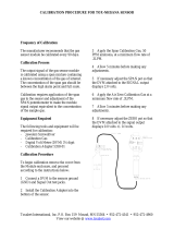
Figure 2-2 Enclosure Dimensions, 2-Wire Units

DOTX-45 Dissolved Oxygen System Part 2– Analyzer Mounting
DOTX-45 12 -
2.2 Wall or Pipe Mount
A PVC mounting bracket with attachment screws is supplied with each
transmitter (see Figure 2-3 for dimensions). The multi-purpose bracket is
attached to the rear of the enclosure using the four flat head screws. The
instrument is then attached to the wall using the four outer mounting holes in the
bracket. These holes are slotted to accommodate two sizes of u-bolt that may be
used to pipe mount the unit. Slots will accommodate u-bolts designed for 1½ “or
2” pipe. The actual center to center dimensions for the u-bolts are shown in the
drawing. Note that these slots are for u-bolts with ¼-20 threads.
Figure 2-3 Wall or Pipe mount Bracket

DOTX-45 Dissolved Oxygen System Part 2– Analyzer Mounting
DOTX-45 13 -
Figure 2-4 Wall Mounting Diagram
Figure 2-5 Pipe Mounting Diagram
ENTER
MENU
ESC
ENTER
MENU
ESC
DOTX-45 Dissolved Oxygen System Part 2– Analyzer Mounting
DOTX-45 14 -
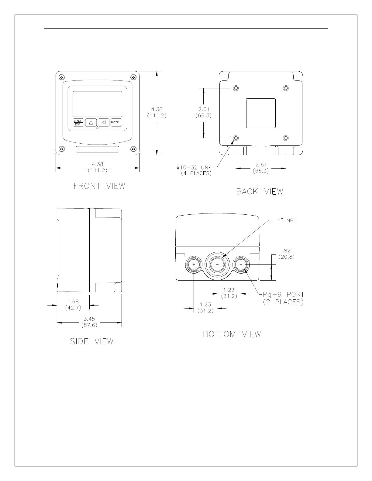
2.4 Panel Mount, AC Powered Monitor
Panel mounting of an AC powered monitor uses the panel mounting flange
molded into the rear section of the enclosure. Figure 2-6 provides dimensions for
the panel cutout required for mounting.
The panel mounting bracket kit must be ordered separately. This kit contains a
metal retainer bracket that attaches to the rear of the enclosure, 4 screws for
attachment of this bracket, and a sealing gasket to insure that the panel mounted
monitor provides a water tight seal when mounted to a panel.
The sealing gasket must first be attached to the enclosure. The gasket contains
an adhesive on one side so that it remains in place on the enclosure. Remove
the protective paper from the adhesive side of the gasket and slide the gasket
over the back of the enclosure so that the adhesive side lines up with the back of
the enclosure flange. Once in place, you can proceed to mount the monitor in
the panel.
Figure 2-6 115/230 VAC Panel Mount and Cut-out
ENTER
MENU
ESC

DOTX-45 - 15 -
Part 3 – Sensor Mounting
3.1 General
Select a location within the maximum sensor cable length for mounting of the
sensor. Locating the sensor within 25 ft. of the transmitter is generally preferred
for ease of operation and calibration.
3.2 Submersion Mounting
Most applications for D.O. monitoring are done using a submersible sensor. This
method can be used where flow is reasonably constant, and hydraulic head does
not vary more than about 10 feet. Oxygen sensors can never be used in
completely stagnant conditions. A flow velocity of at least 0.3 feet per second is
normally required for measurement.

DOTX-45 - 16 -
Part 4 – Electrical Installation
4.1 General
The DOTX-45 is powered in one of two ways, depending on the version
purchased. The 2-wire version is a 16-35 VDC powered transmitter. The
integral 115 VAC version requires line power. Please verify the type of unit
before connecting any power.
WARNING: Do not connect AC line power to the 2-wire module.
Severe damage will result.
Important Notes:
1. Use wiring practices that conform to all national, state and local
electrical codes. For proper safety as well as stable measuring
performance, it is important that the earth ground connection be made
to a solid ground point from terminal 12 (Figure 4-1). The AC power
supply in the transmitter, contains a single 100mA slo-blo fuse. The
fuse is located adjacent to TB5 and is easily replaceable.
2. Do NOT run sensor cables or instrument 4-20 mA output wiring in the
same conduit that contains AC power wiring. AC power wiring should
be run in a dedicated conduit to prevent electrical noise from coupling
with the instrumentation signals.
3. This analyzer must be installed by specifically trained personnel in
accordance with relevant local codes and instructions contained in this
operating manual. Observe the analyzer's technical specifications and
input ratings. Proper electrical disconnection means must be provided
prior to the electrical power connected to this instrument, such as a
circuit breaker - rated 250 VAC, 2 A minimum. If one line of the line
power mains is not neutral, use a double-pole mains switch to
disconnect the analyzer.
4.2 Two-Wire
In the two-wire configuration, a separate DC power supply must be used to
power the instrument. The exact connection of this power supply is dependent
on the control system into which the instrument will connect. See Figure 4-1 for
further details. Any twisted pair shielded cable can be used for connection of the
instrument to the power supply. Route signal cable away from AC power lines,
adjustable frequency drives, motors, or other noisy electrical signal lines. Do not
run sensor or signal cables in conduit that contains AC power lines or motor
leads.
DOTX-45 Dissolved Oxygen System Part 5 – Sensor Assembly
DOTX-45 17 -
Figure 4-1 Loop-Power Connection
Notes: 1. Voltage between Terminals 9 and 10 MUST be between 16 and 35 VDC.
2. Earth ground into Terminal 12 is HIGHLY recommended. This connection
can greatly improve stability in electrically noisy environments.
DOTX-45 Dissolved Oxygen System Part 5 – Sensor Assembly
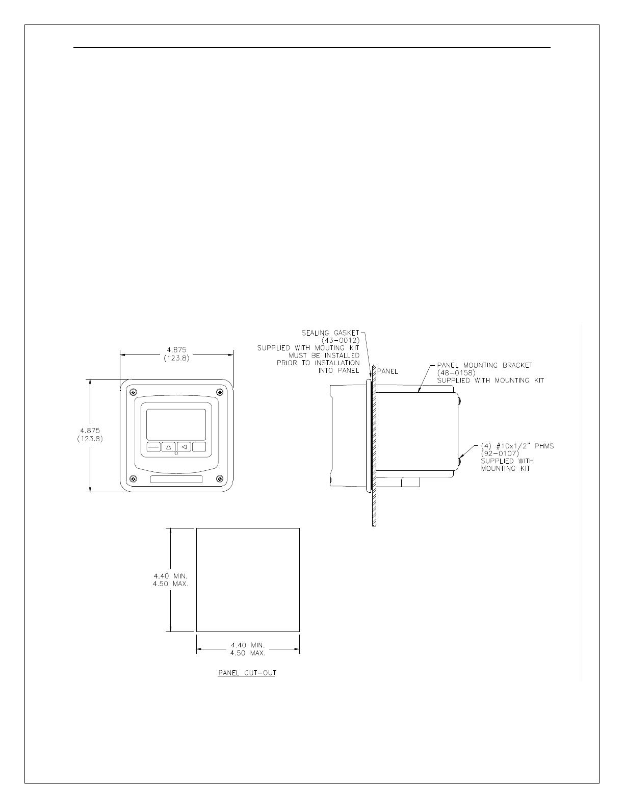
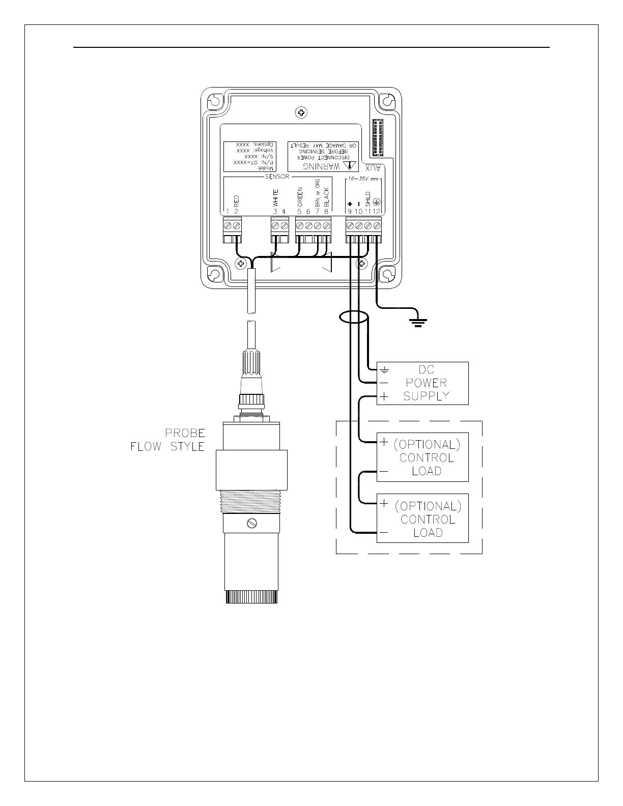
DOTX-45 18 -
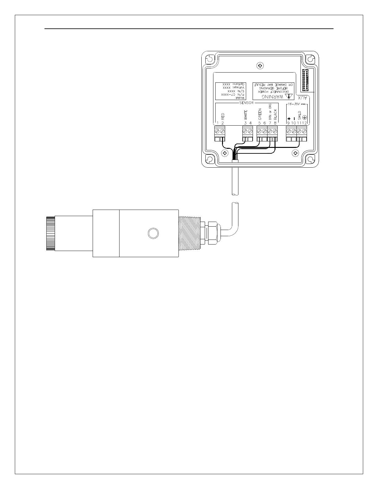
Figure 4-2 Submersible Sensor Connection
4.21 Load Drive
The amount of resistance that the analog output can drive in the 115 VAC
version is fixed. However, in the two-wire configuration, the load-drive level is
dependent on the DC supply voltage provided to the controller.
The two-wire instrument can operate on a power supply voltage of between 16
and 35 VDC. The available load drive capability can be calculated by applying
the formula V/I=R, where V=load drive voltage, I=maximum loop current (in
Amperes), and R=maximum resistance load (in Ohms).
To find the load drive voltage of the two-wire DOTX-45, subtract 16 VDC from the
actual power supply voltage being used (the 16 VDC represents insertion loss).
For example, if a 24 VDC power supply is being used, the load drive voltage is 8
VDC.
The maximum loop current of the two-wire DOTX-45 is always 20.00 mA, or .02
A. Therefore,

DOTX-45 Dissolved Oxygen System Part 5 – Sensor Assembly
DOTX-45 19 -
For example, if the power supply voltage is 24 VDC, first subtract 16 VDC, then
divide the remainder by .02. 8/.02 = 400; therefore, a 400 Ohm maximum load
can be inserted into the loop with a 24 VDC power supply.
Similarly, the following values can be calculated:
4.3 115 VAC w/Relays
In the 115 VAC configuration, a DC power supply is mounted into the inside rear
of the enclosure. The power supply must be ordered with the proper operating
voltage. Verify that the unit requires 115 VAC before installing. Also verify that
power is fully disconnected before attempting to wire.
AC powered systems are supplied with 3 cable gland fittings and two ½” conduit
adapters. One of the cable glands has a larger hole in the rubber gland and
should be used for the power cord entry if a flexible power cord will be used for
installation. One of the cable glands with the smaller gland opening should
normally be used for the sensor cable. Cable glands and conduit hubs will screw
into any of the three threaded holes on the bottom of the enclosure.
Connect HOT, NEUTRAL, and GROUND to the matching designations on
terminal strip TB5.
(Power Supply Voltage
-
16)
.02
= R
MAX
Power Supply Voltage (VDC)
Total Load (Ohms)
16.0 0
20.0 200
24.0 400
30.0 700
35.0 950
WARNING
Disconnect line power voltage BEFORE connecting
line power wires to Terminal TB5 of the power supply.
The power supply accepts only standard three-
wire
single phase power. The power supply is configured
for 115 VAC or 230 VAC operation at the f
actory at
time of order, and the power supply is labeled as
such. Do NOT connect voltages other than the
labeled requirement to the input.
/