Kenmore 596.50002100 User manual

Category
Fridges
Type
User manual
ORDER # 67003291
®
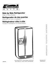
Side-by-Side Refrigerator
Use & Care Guide
Refrigerador D_plex
Guia para el Usoy Cuidado
R_frigerateur _ Compartiments Juxtaposes
Guide D'utilisationet D'entretien
Models:
596.53462300,
596.52672200,
596.50002100,
596.50012100,
596.53463300,
596.52673200,
596.50003100,
596.50013100,
596.53464300,
596.52674200,
596.50004100,
596.50014100,
596.53469300,
596.52679200,
596.50009100,
596.50019100
II'1
I
I
Zi
O
r"'
PartNo.12591318 Sears, Roebuck and Co., Hoffman Estates, IL 60179 U.S.A. www.sears.com
FormA/3/03 Sears Canada, Inc.,Toronto,Ontario, Canada M5B2B8 Au Canada, www.sears.ca
IMPORTANTSAFETYIHFORMATIOH
YOUHEEDTOKHOW
ABOUTSAFETY
IHSTflUCTIOHS
Warningand ImportantSafety
Instructionsappearing in this manual are
not meantto cover all possible
conditions and situations that may occur.
Common sense,caution, and care must
be exercisedwhen installing,
maintaining,or operating refrigerator.
Always contact your dealer,distributor,
service agent, or manufacturerabout
problems or conditions you do not
understand.
RECOGNIZE SAFETY
SYMBOLS, WORDS,
LABELS
DONOT attemptserviceif
understoodor f they arebeyondpersona
skilllevel.
the cord.
toInstallationInstructions.All
Repace wornpower cords and/or oose 13ugs.
manufacturer'sstorageand ideal
'" "nentinstructionsfor itemsbeingstoredin
2
SAVETHESEIHSTRUCTIOHS
PROTECTION
I
INTHE U.S.A.
Congratulationson makinga smart
purchase.Your new Kenmore®
applianceisdesigned and manufactured
foryears of dependable operation. But
likeall products, it may require
preventivemaintenance or repair from
timeto time. That is when havinga
MasterProtection Agreement can save
youmoney and aggravation.
Purchasea Master Protection
Agreementnow and protect yourself
fromunexpected hassle and expense.
TheMaster Protection Agreementalso
helpsextend the life of your new
appliance. Here is what is included in
theagreement:
> Expert service by our 12,000
professional repair specialists.
> Unlimited service and nocharge for
parts and labor on all covered
repairs.
> "No-lemon" guarantee - replacement
of your covered product if more than
three product failures occur within
twelve months.
> Product replacement if your covered
product cannot be fixed.
> Annual Preventive Maintenance
Check at your request- no extra
charge.
> Fast help by phone- non-technical
and instructional assistanceon
products repaired in your home, plus
convenient repair scheduling.
> Power surge protection against
electrical damage due to power
fluctuations.
> Rental reimbursement if repair of
your covered product takes longer
than promised.
Once you purchase the Agreement, a
simple phone call is all that ittakes for
you to schedule service. Youcan call
anytime day or night, or schedule a
service appointment online.
Sears has over 12,000 professional
repair specialists, who have access to
over 4.5 millionquality parts and
accessories. That is the kind of
professionalism you can count on to
help prolong the life of your new
purchase for years to come. Purchase
your Master Protection Agreement
today!
Some limitations and exclusions apply.
Forprices and additional information,
call 1-800-827-6655.
Sears Installation Service
ForSears guaranteed professional
installationof home appliances and
itemslike garage door openers and
water heaters, in the U.S.A. call
1-800-MY-HOME®.
TEFtAF!CEAGflEEMEHTS
IN CANADA
Your purchase has added value because
you can dependon Sears HomeCentral®
for service. With over 2,400 Service m
Techniciansand access to over 900,000
parts and accessories,we have the
tools, parts, knowledge and skillsto _=11]!
ensure our pledge: We ServiceWhat
We Sell. ,_
Your Kenmore®appliance is designed,
manufactured and tested to provide
years of dependable operation. Yet any
major appliance may require service
from time to time. The Sears
MaintenanceAgreement offers you an
outstanding service program, affordably
priced.
Sears MaintenanceAgreement
> Isyour way to buy tomorrow's service
at today's price.
> Eliminates repairbills resultingfrom
normal wear and tear.
> Providesfor non-technicaland
instructional assistance.
> Even if you don't need repairs,
provides an annual Preventive
Maintenance Check, at your request,
to ensure that your applianceis in
proper running condition.
Some limitations apply. For information
concerning SearsCanada Maintenance
Agreements, call 1-800-361-6665.
WARRAHTY
Full One YearWarranty on
Refrigerator
For one year from thedate of purchase,
whenthis refrigerator is operatedand
maintained accordingto instructions
attachedto or furnished with it, Sears
will repair it, free of charge, ifdefective
in materialor workmanship.
Full Five YearWarranty on Sealed
RefrigerationSystem
Forfive years from the date of purchase,
when this refrigerator is operatedand
maintainedaccording to instructions
attached to or furnished with it, Sears
will repairthe sealed system (consisting
of refrigerant,connectingtubing and
compressor motor) free of charge, if
defective in material or workmanship.
The above warrantycoverage applies
only to refrigeratorswhich are used for
storage of food for private household
purposes. It excludesoriginal and
replacement Kenmoreice & water filter
cartridges. Original and replacement
cartridges are warranted for 30 days,
parts only, against defects in material or
workmanship.
Warrantyservice is availableby
contacting 1-800-4-MY-HOME*
(1-800-469-4663).
This warranty appliesonly while this
product is in use in the UnitedStates.
This warranty gives you specific legal
rights, and you may also have other
rights,which vary from state to state.
Sears, Roebuck and Co., Dept. 817WA,
Hoffman Estates, IL60179
NOTE: Some ReverseOsmosis home
water systems cause low water
pressure.Low water pressure can affect
the water and ice dispensing system by
causing small or hollowice cubesand
slow water flow from the dispenser.
Service problems relatedto the home's
ReverseOsmosis water system are not
covered bythe warranty.
PRODUCTRECORD
Inthe space below recordthe model
and serial numbers and purchase date
of your refrigerator.Youwill find the
modeland serial number sticker inside
the refrigerator sectionon the left wall.
Model Number: 596.
Serial Number:
Purchase Date:
Keep this booklet and your Sears
sales receipt in a safe place for future
reference.
4
(OHTEHTS
Important Safety Information......................................................................................2
WhatYou Needto KnowAboutSafety Instructions...................................................2
ProtectionAgreements ................................................................................................3
MasterProtectionAgreements- U.S.A.....................................................................3
MaintenanceAgreements- Canada.........................................................................3
Warranty ........................................................................................................................4
Product Record .............................................................................................................4
Installing YourRefrigerator ....................................................................................6-10
Measuring the Opening .............................................................................................6
TransportingYour Refrigerator...................................................................................6
Selecting the Best Location.......................................................................................6
How to Installand RemoveHandles .........................................................................7
Removingthe Doors and Hinges...............................................................................8
Replacing the Doors ..................................................................................................8
How to Installand RemovePanels............................................................................9
How to Connect the Water Supply...........................................................................10
How to LevelYour Refrigerator................................................................................11
Setting and MaintainingProper Temperatures ........................................................12
Dial TemperatureControls.......................................................................................12
ElectricTemperatureControls..................................................................................12
Fresh FoodStorage.................................................................................................12
Frozen FoodStorage...............................................................................................12
About YourWater Filter ........................................................................................13-14
Water Filter Installationand Removal......................................................................13
Water Filter Data......................................................................................................14
Fresh Food Features.............................................................................................15-16
InteriorShelves........................................................................................................15
Door Storage............................................................................................................15
Climate-ControlledDrawers.....................................................................................16
Storage Drawers......................................................................................................16
Freezer Features .........................................................................................................17
Automatic Ice Maker................................................................................................17
InteriorShelves........................................................................................................17
Storage Drawers......................................................................................................17
DoorStorage............................................................................................................17
DispenserFeatures ...............................................................................................18-22
DispenserLight........................................................................................................18
DispenserPad .........................................................................................................18
RemovableTray.......................................................................................................18
Water DispenserOperation.....................................................................................18
Five-ButtonControl Features...................................................................................19
ElectronicControl Features................................................................................20-21
HiddenElectronicControl Features.........................................................................22
Hints and Care.......................................................................................................23-24
Howto CleanYour Refrigerator...............................................................................23
Howto RemoveOdors from Refrigerator................................................................24
EnergySaving Ideas................................................................................................24
Howto Removeand Replace Light Bulbs...............................................................24
Normal Operating Sounds.........................................................................................25
Troubleshooting ....................................................................................................26-27
Operation.................................................................................................................26
Ice and Water...........................................................................................................27
Fran£ais .......................................................................................................................29
EspaSol........................................................................................................................57
Service ..........................................................................................................Back Cover
m
5
IHSTALLIHGYOURREFRIGERATOR
These instructionswere providedto aid
you in the installation ofyour
refrigerator.
IGTileOPEHIHG
When installing your refrigerator,please
referencechart belowfor clearance
requirements.
Subflooring or floor coverings (i.e.
carpet, tile, wood floors, rugs) may make
your opening smaller than anticipated.
Some clearance may be gained by
using the levelingprocedure under
How to Level Your Refrigerator
(page 11).
Recommended
.Clearance
Top Sides
Unit Total
Volume Rear
Less than
N/A N/A _"
23 cu. ft.
Greaterthan
_" N/A _"
23 cu. ft.
IMPORTANT: If refrigeratoris to be
installed intoa recesswhere top of
refrigeratoris completely covered, use
dimensionsfrom floor to top of hinge
cap to verify proper clearance.
TRAHSPORTIHGYOUR
REFRIGERATOR
Followthese tips when movingthe
refrigeratorto final location:
NEVERtransport refrigerator on its
side. If an upright position is not
possible,lay refrigerator on its back.
Allow refrigerator to sit uprightfor
approximately 30 minutesprior to
plugging refrigeratorin to assure oil
returnsto the compressor.Plugging
refrigerator in immediatelymay cause
damageto internalparts.
Usean appliancedolly when moving
refrigerator.ALWAYStruck
refrigeratorfrom its sideor back-
NEVER from its front.
Protectoutside finish of refrigerator
during transport bywrapping cabinet
in blankets or inserting padding
betweenthe refrigerator and dolly.
Securerefrigeratortodollyfirmlywith
stropsor bungeecords.Threadstraps
throughhandleswhenpossible.DONOT
overtighten.Overtighteningrestraintsmay
dentordamageoutsidefinish.
Observe these points when choosingthe
final location for your refrigerator:
DO NOT install refrigerator near
oven, radiatoror other heat source. If
not possible,shield refrigerator with
cabinet material.
DO NOT install where temperature
falls below 55° F (13° C). Malfunction
may occur at this temperature.
To assure proper door closure, follow
the levelinginstructionsin the
section, How to Level Your
Refrigerator (page 11),
6
HOWTOINSTALLAND
RE, OVEHANDLES
Foreasier installation, some
refrigeratorsmay have been delivered
withthe handles off. Pleasesee the
interiorof the fresh food sectionto
locatethe handle assembly. In case
futuretransport of the refrigerator is
necessary,the removal instructions have
beenincluded here for your
convenience.
Handledesign may vary from
refrigeratorto refrigerator. Please
referencethe instructionsfor the
appropriate handle design below.
INSTALLING FRONT-
MOUNTED HANDLES
1,Remove two V,"hex nutscrewsfrom
bottom of door.
,
Align door handle with
top and bottom sets of
door clips, and slide
down until screw holes
on bottom of handle
match with door screw
holes.
Insert ¼" hex nut screws
previously removed into
screw holes at bottom of
handle section.
Snap trim over bottom
portion of handle and
retainer on bottom door.
Repeat instructions 1-4
toinstall other handle.
REMOVING FRONT-
MOUNTED HANDLES
1. Remove handle trim with a very small
flat-blade screwdriver.
.
.
,
IMPORTANT: Wrap blade of
screwdriver with masking tape to
avoid damaging refrigerator.
tt
Removetwo handle It
base screws.
Pull handle up and
outto release from
refrigerator. Fit may
be tight.
Repeat instructions 1-3 to remove
other handle.
INSTALLING FULL-
LENGTH EXTRUDED
HANDLES
,A
top door 1Ik
1. Release
trim by removing
q
Phillips screws from
top of fresh food
door.
t
,
> Retain Phillipsscrews for later
replacement.
Align notches on back of handle with
retaining clips on doors. Insert clips
into notches
and slide _
handle down
until it contacts
bottomtrim.
,
,
Replace top door trim
with Phillipsscrews
retainedfrom trim
removal.
Repeat instructions
1-3 to install other
handle.
REMOVING FULL-LENGTH
EXTRUDED HANDLES
b ai old possible inju_ _d d_m_ge
to _o_y, t_pe de_iat _# paSels
(so_e moael_)_e_Ore_ _ _c_
1. Release top door trim _w
by removing Phillips [
screws from top of _"
fresh food door.
Retain Phillips
screws for later
replacement.
2. Grasp handlefirmly
with both hands and
slide handle upward
approximately _/4"to
release.
3. Repeat instructions
1-3 to remove other handle.
7
IHSTALLIHG
riNGTHEDOOflS
ANDHINGES
Some installationsrequire doer removal
to get refrigeratorto final location.
Toavoid Severepers0nai i or
' Discon
i
attached
Toavoid propertydamage, observe
protective material,prior to moving
refrigerator.
> To avoiddamage or breakageto
adjusting bolt, do not use power
tools to correct leveling.
> DO NOT adjust refrigeratorto be
any shorter than 68Y2tall (minus
hingeand cap). Doing so may
damage undersidecomponents.
1. Removetoe grille and bottom hinge
covers.
> Openboth doors 180degrees, or
as wide as possibleto remove.
2. While pinching white collar (A) to the
blue connector (B),pull water line
from connector.
B
IMPORTANT:When reconnectingwater
line, cut off tubing atfirst available
scored line before inserting into
connectorcollar.
3. Removetop hinge cover by removing
Phillipsscrew.
4. Close doors.
5. Unscrew %6"hex headscrews from
top hinges.
DO NOT remove either green
ground wire or wire connecting
center screw.
6. Detachmainwire connectorharness
and red wire harness.
> Todetach mainwire harness, use
a flat blade screwdriveror finger-
nail to press junction point
betweentwo connectorsto
release.
> Todetach red wire harness,press
tab on undersideof connectorto
release.
7. Remove top hingesalong with doors.
8. Removebottom hingeswith a¾"hex
head driver.
16THEDOORS
> To replace the doors, follow the steps
in Removing the Doors and Hinges
in reverseorder.
IMPORTANT: When reconnectingwater
line, cut off tubing atfirst available
scored line before inserting into
connector collar.
8
into place
when d6or handlesareremove&
property
following:
> Refrigeratorpanelsshould not
weigh morethan
kilograms)and fr_
should not weigh
pounds(7 kilogra
> Protectsoft vinyl
with cardboard, n
protective material.
> Protecthands and arms by
wearing gloves.
NOTE:
> Toprotectdoor surfacesfrom being
scratched,cover back edges of
decorator panels by placing masking
tape along back edges.
>- Save all screws and reuse in original
locations.
Y4"(6 mm) Panel Dimensions
Extended
Door
Panel
Fresh food
door
Upper
dispensing
freezer door
Lower
dispensing
freezer door
Non-
dispensing
freezer door
Panel Panel
Height Width
66 T'4" 18 _'A6"
(169.5 cm) (48.1 cm)
18 1/8" 13 _sAs"
(46 cm) (36.4 cm)
32 %2" 13 1_/i,"
(61.5 cm) (35.4 crn)
66 ¾" 13 1_,6"
(169.5 cm) (35.4 cm)
INSTALLING PANELS
1. Removetoptrimscrews with a
Phillips screwdriverand remove top
trim.
.
,
.
,
.
Slide handle upwarduntil
loose. Remove handle
from door.
Removedoor
retainerclips with
a ¼"hex head
driver.
Slide bottomof panels into bottom
door trim until hinge side of decorator
panel rests under hinge sidetrim.
REMOVING PANELS
1. Removetop trim screws with a
Phillipsscrewdriver and remove top
trim.
.
.
IMPORTANT:Tapetops of panels to 4.
door to prevent panelsfrom falling.
Reinstalldoor r__ 5.
retainerclips with
a ¼"hex head
driver.
Reinstallhandle by inserting retaining
clips on door into notcheson backof
handle.
IMPORTANT:Tapetops of panelsto
door to prevent panelsfrom falling.
> Slidehandledown until it contacts
bottomtrim.
7. Removetape from
tops of panels
beforereinstalling
top door trim with
Phillipsscrews
removed in step 1.
Slide handle upward until
loose. Removehandle
from door.
Removedoor
retainerclips with
a ¼" hex head
driver.
Removetape to slide panels out of
door trim.
Refer to steps 5, 6 and 7 of
Installing Panels to install handles
and trim.
m
9
YOURREFRIGERATOR,e,T.
)WTOCONNECTTHE
WATER$11PPL¥
the
MATERIALS NEEDED
> Y4"outer diameter flexible copper
tubing
Brass compression nut and sleeve for
Y4"outerdiametercopper tubing.
Shut-offvalve (requiresa Y4"holeto
be drilled intowater supply before
valve attachment)
> Adjustable wrench
> Y4"hex nut driver
NOTE:Add 8' to tubing length neededto
reachwater supply for creation of
service loop.
1. Create service loopwith tubing using
careto avoid kinksintubing.
2. Removeplastic capfrom watervalve
inlet port.
4. Placeend of coppertubingintowater
valve inletport. Shapetubing slightly-
DO NOT KINK - so that tubingfeeds
straight into inlet port.
5. Slide brass nut oversleeve and
screw nut into inlet port. Tighten nut
with wrench.
IMPORTANT:DO NOT overtighten.
Cross threading may occur.
6. Pull on tubingto confirmconnection
issecure. Connecttubing to frame
with water tubing clamp (C) and turn
on water supply.Check for leaks and
correct, if present.
C
3. Placebrass nut (A) and sleeve (B) on
copper tube end as illustrated.
A
7. Monitor water connectionfor 24
hours. Correct leaks, if necessary.
!/ iii ii /C ¸ i
10
)WTOLEYELYOUR
REFRIGERATOR
If your refrigerator requiresan ice maker
water supply connection, referto How
to Connect the Water Supply (page
10) before levelingyour refrigerator.
MATERIALS NEEDED
>_¾"hex head driver
:_ Level
,
,
Removetoe grille and bottom bracket
covers (see previous instructions).
Turnboth front adjustmentscrews (A)
clockwiseto raiseand counter-
clockwiseto lower.
o
3. Turn bothrear adjustmentscrews (B)
clockwiseto raiseand
counterclockwiseto lower.
.
Usinga level, make sure front of
refrigeratoris _'4"(6 mm)or Y2bubble
higher than back of refrigerator.See
leveling step 3 for assistance.
.
If required,correct rocking of
refrigeratorby turning rear
adjustmentscrew clockwiseto raise
rocking corner. If doors are
uneven...
>_Determinewhich door needs to be
raised.
>_Turn front roller adjustment screw
clockwiseto raisefront cornerof
door.
>>
If the refrigerator has reachedthe
limit of its adjustment range, and
doors are still not level-lower
opposite door by turning roller
adjustment screw
counterclockwise.
Check with leveltoverify Y,"tilt to
the back for proper door closure.
If refrigerator is aligned and stable,
replacetoe grille and hinge
covers.
I11
Z
O
m
11
This refrigerator is designed to operate at a householdtemperature of 55° to 100° F (13° to 43° C).
I 4 i
Temperature
Control
Electronic Temperature Control
OFF
_ tEnEt I
ON
DISPENSER LIGHT
GOOD 0 LIGHT
CHANGE o SENSOR
ITIAL(OHTROLSETTIHGS
DIAL CONTROLS
Y
1. Locate refrigerator _--__"
and freezer control
on upper-left wall of
fresh food section.....
_m_Tor
2. Themanufacturer's ,' ,
recommendation
settingforboth
compartmentsis 3_.
3. Letthe refrigerator run at least 8 to
12 hours before adding food.
4. Allow 24 hoursfor temperature to
stabilize.
ELECTRONIC CONTROLS
1. Toset temperatureofthefreezer, use
7`
the...... buttons next tothe
Y
button.
> Usethe 7, to raise the
temperatureof the freezer section,
or the Y to lowerit.
> Pressthe _ button to confirm
the settings.
2. Toset temperatureof the fresh food
/%,
_Mws_
section, usethe v buttons next to
the _ button.
Usethe ^ buttonto raisethe
temperatureofthe freshfood
section,or the v buttonto lowerit.
> Press the _ buttonto confirm
the settings.
3. Allow24 hoursfor temperatures to
stabilize.
NOTE:
Thetemperature display on the LED
screen may fluctuate after being set
as the refrigerator cycles to maintain
the set temperature.
After 24 hours from adding food, you
may decidethat one or both
compartmentsshould be colder or
warmer. Followthe instructions below
for proper temperatureadjustment.
NOTE:
Dueto design of refrigerator,always
starttemperatureadjustments with
freezer section.
DO NOTchange either control more
thanone numberat a time.
Allow 5-8 hoursfor temperatures to
stabilize.
Changingeither control will have
some effect on the temperature ofthe
other compartment.
If freezer or refrigerator istoo cold:
> Changecontrol to next higher
number.
If freezer or refrigerator istoo warm:
> Changecontrol to next lower number.
FRESH FOOD STORAGE
Thefresh food compartmentofa
refrigeratorshould be keptbetween
34° F and40° F withanoptimum
temperatureof37° F.Tocheckthe
temperature,placean appliance
thermometerin a glass ofwaterand
placeinthe centeroftherefrigerator.
Checkafter 24 hours. Ifthe
temperatureisabove40° F adjustthe
control.
FROZEN FOOD STORAGE
Thefreezer compartment ofa
refrigeratorshould be kept at
approximately F.Tocheckthe
temperature,placean appliance
thermometerbetween the frozen
packagesand checkafter 24 hours. If
thetemperatureisabove0° F, adjust
thecontrol.
ABOUtyourw terfIlTER...
WATERfIlTERINSTALLATION
ANDREMOVAl
INSTALLING
WATER FILTER
1. Removebluebypasscap andretain
for possiblelateruse.
2. Removesealing labelfrom end of
filter and insert intofilter head.
3. Rotategently clockwise untilfilter
stops,and snap filter cover closed.
4. Reduce waterspurts by flushing air
from system. Runwatercontinuously
for 2 minutes throughdispenser until
waterruns steady.
Additionalflushing may be
required insome households
wherewater is of poor quality.
REPLACING
WATER FILTER
IMPORTANT: Airtrappedinsystem
maycausewaterandcartridgetoeject.
Usecautionwhenremoving.
1. Turnfilter counterclockwiseuntil it
releases from filter head.
.
.
Drain water from filter into sink,and
dispose in normal household
garbage.
Wipe up excess waterinfilter cover
and continue with InstallingWater
Filter, steps2 and3.
WHEN DO I CHANGE THE
WATERFILTER?
The dispenserfeatures a water filter
change indicator.For instructionson
how to operateand reset this feature,
refer to the DispenserFeatures section
(page 18).
IMPORTANT:Condition of water and
amountused determineslife span of
water filter cartridge. If water use is
high, or ifwater isof poor quality,
replacementmay need to take place
more often.
HOW DO I ORDER A
REPLACEMENT FILTER
CARTRIDGE?
Kenmore®replacementwater filter
cartridge model 9005 is available
through Searsdealers and servicers.
You may also order through Sears by
using the informationon the back cover.
I'M TRYING TO DISPENSE
WATER TO FLUSH THE
SYSTEM. WHERE'S THE
WATER?
Duringinitial use, allow about a 1 to 2
minute delayin water dispersal to allow
internalwater tank to fill.
WHAT IF I CHOOSE NOT
TO USE THE WATER
FILTRATION SYSTEM?
Dispenserfeature may be usedwithout
water filter cartridge. If you choose this
option, replacefilter with blue bypass
cap.
II'1
m
13
14
FI[T[RDATA
SYSTEM SPECIFICATION AND PERFORMANCE DATA
SHEET REFRIGERATOR WATER FILTER CARTRIDGE
MODEL 9005
Specifications
Service Flow Rate (maximum) ....................................................0.75 GPM (2.83 L/min)
Rated Service Life Model 9005 (maximum)................................500 gallons/1892 liters
MaximumOperating Temperature...............................................100° F/38° C
MinimumOperatingTemperature................................................33° F/l° C
MinimumPressure Requirement.................................................35 psi/138 kPa
MaximumOperating Pressure.....................................................120psi/827 kPa
PERFORMANCE DATA
Substance
'Lead
Lead
Cyst
Turbidity
Lindane
Atrazine
Chlorine
Particulate**
2,4-D
Asbestos
Influent Challenge
Concentration
0.15 mg/L +/- 10%
0.15 mg/L +/- 10%
Minimum50,000/L
11+/-1NTU
0.002 mg/L +/- 10%
0.009 mg/L +/- 10%
2.0 mg/L +/- 10%
at least 10,000
particles/mL
0.210 mg/L +/- 10%
107to 10Sfibers/L;fibersgreaterI
i
than !0 micrometersinlength
Effluent Average%J Maximum
Average Reduction Effluent
0.001 mg/L 99.33% 0.001 mg/L
0.002 mg/L 98.66% 0.003 mg/L
lcount/mL 99.99% 3 count/mL
0.12 NTU 98.98% 0.18 NTU
0.00005 mg/L 97.62% 0.00005 mg/L
0.0002 mg/L 97.93% 0.0005 mg/L
0.09 mg/L 95.26% 0.17 mg/L
900 count/mL 99.66% 2400count/mL
45.45 ug/L 84.42% 100 ug/L
0.16 MFL/mL 99.96% 0.16 MFL/mL
Min. Required Inlet
Reduction pH
0.010 mg/L 6.5
0.010 mg/L 8.5
> 99.95% NA
O.5 NTU NA
I
0.00002 mg/L ! NA
0.003 mg/L NA
>75% NA
>85% NA
0.0017 mg/L NA
99% NA
Tested using a flow rate of0.75 GPM (2.83 L/rain.) and a maximum pressure of 120 psi (827 kPa)
under standard laboratory conditions, however, actual performance may vary. Health Claim
Performance tested and certified by NSF International
** Particle size range classification of test. Particles used were 0.5-1 microns.
State of California
Department of Health Sewices
Water Treatment Device
Certificate Number
01 - 1486
Date Issued: September 21. 2001
Date Revised: March 20, 2O02
GENERAL USE
CONDITIONS
Read this PerformanceData Sheetand
compare the capabilitiesof this
refrigeratorwith your actual water
treatment needs.
DO NOT usethis productwhere water
is microbiologicallyunsafe or of
unknownqualitywithout adequate
disinfection installedbeforeor after
filtration system. Systemscertified
for cyst reduction may be used on
disinfectedwater that may contain
filterable cysts.
Use onlywith coldwater supply.
Check for compliancewith the state
and local laws and regulations.
The retractablewater filtration system
uses a 9005 replacementcartridge (see
Searscontact information atthe back of
your Use and Care Guide to order).
Timely replacementoffilter cartridge is
essential for performancesatisfaction
from this filtration system. Please refer
to the applicablesection in this Use and
Care Guide for general operation,
maintenancerequirementsand
troubleshooting.
This systemhas been tested according
toANSI/NSF42 and 53 for reduction of
the substanceslisted below. The
concentrationof the indicated
substancesin water enteringthe system
was reducedto a concentration less than
or equal tothe permissiblelimit for water
leavingthe system, as specified in
ANSI/NSF42 and 53.
wFso-wl500 wFso 500gal
WFS0-N[3CO WFSO 300 gat
WFS0-KWlSO( 40 9005 300g_l
WFS0-KNI3CO 4_ _O05 300g_l
OWF_0-WlSO0 JVmS 5(_ _al
OWFSO-_I30a OWF5 J_Ogal
Manuf_ctu_r: PeriL.pure{a_q,o=,=o
3he water z_a=ment device,s) IJs_ _ this certW_te have met the tt_thtg _qui_¢nts pbrsua_t to Section 116830 of the
Health _.d Safety Caaa for th_ foLly*tug Ueaah _lated _ma_n_ts:
_L_3&t,_J_ IJ_9_f.2RaSl_ei_lConl_tnan_
Cysls Asb_
Llndan_
Tested and certified by NSF International against ANSI/NSF Standards 42 and 53 in
models WF50-KNI300 and WF50-KWl500 for the reduction of:
Standard No. 42: Aesthetic Effects
Taste and Odor Reduction
Chlorine Reduction
Mechanical Filtration Unit
Particulate Reduction Class 1
Standard No. 53: Health Effects
Chemical Reduction Unit
Lead, Atrazine, Lindane and 2, 4-D Reduction
Mechanical Filtration Unit
Cyst, Turbidity and Asbestos Reduction
@
PentaPure
INI ()_[)RAI_I)
1000ApolloRoad
Eagan, Minnesota U.S.A.
EPAEST#35917-MN-1
TERIORSHELVES
>- Hande tempered glass shelves
carefully.Shelves may break
suddenly if nicked;scratched,or
expOsedto suddentemperature
change.
SPILLPROOF SHELVES
SpillproofShelves hold , _
simple spills for easier _ n
cleaning.
Toremove shelves, lift 'I_11 II
up and out.
Toinstall shelves, reverseabove
procedure.
SpillproofSlide-out
Shelves feature the
convenienceof
easy cleaning
with a pullout "" '_ _III
design to reach
items in the back. Forease of cleaning,
glass shelf may be removed by pulling
to full extension and lifting out of frame.
STORAGE
BEVERAGE
COMPARTMENT
(SOME MODELS)
The temperature-controlledbeverage
compartmentkeepsbeveragesand
other itemscolder than the rest of the
fresh food section. Air inlet allows air
from the freezer section to pass to the
beveragecompartment.
Controls
The control is located on the left wall of
the fresh food section. Control adjusts
amount of air circulating inthe beverage
compartment. Turn control clockwisefor
colder temperature.
To remove and install the beverage
compartment:
If located directly abovethe beverage
compartment, dairy center or door
bucket may need to be removed.
Refer to appropriate instructions and
remove item.
Slide the
beverage
compartment
assembly up
and pull
straight out.
To install,align one of the cold air
intake holes (A) with one of the two
air inlets (B) in door liner. Push
assembly down onto door liner
retainer until it stops.
IMPORTANT: The beverage
compartment will not operate properly if
air intake holes are notaligned with air
inlet in door liner.
DAIRY CENTER
The Dairy Center provides convenient
storage for items such as butter, yogurt,
cheese, etc.
This compartment is an adjustable
feature located in the door. It can be
moved to several different locations to
accommodatestorage needs.
To remove and install bin:
Toremove,
slide dairy
center up and
pull out.
Toinstall, slide
assembly in
above desired door liner retainer and
push down until it stops.
To remove and install dairy door:
To remove, press in sides of dairy
door and pull out.
Toinstall, slide sides of dairy door
inside dairy center until hinge points
snap into place.
TILT-OUT DOOR BUCKETS
(SOME MODELS)
The Tilt-Out Bucketassemblyconsists
ofa bucket andframe, providing
adjustable,convenientstorage for food
itemsindoor.The bucketassemblytilts
forward for easyaccessofitems,and
lifts out for ease in cleaningand
adjusting.
To remove and install bucket:
To remove
bucket, tip bucket
forward and pull
straight out to
remove.
I11
Toinstall bucket, slide bucketinto
bucket frame and push bucket
upright.
To adjust bucket frame:
Remove bucket per ">Y_I I1|11
above instructions.
Lift frame off door
support and place in
desired door location.
DOOR BUCKETS
Door Buckets adjust tomeetindividual
storageneeds.
To remove, slide bucket
up and pull straightout.
To install,
reverse above
procedure.
]5
(L[MATP(ONTROLL[D
DRAW[R$
HUMIDITY-CONTROLLED
CRISPER DRAWERS
The Humidity-ControlledCrisper
keeps producefresh longer by providing
an environmentwith adjustable humidity.
Controls
The humidity-controlledcrisper controls
regulatethe amount of humidityin the
crisper drawer. Use the low settingfor
non-leafy produce. Usethe high setting
for leafy produce.
To
remove and install drawer:
To remove,pull drawer out to full
extension. Tilt up front of drawer and
pull straight out.
Toinstall,guide drawer intoframe
and push back until drawer is flush
with rear wall.
To remove and install shelf:
Toremove, lift shelf
from wall supports.
Toinstall, lower
shelf onto wall
supports and push
in until shelf isflush
with rear wall.
PRODUCE STORAGE TIPS
Pleaseobservethefollowing rules when
storing producein humidity-controlled
crisper drawers:
> DO NOTwash produce before
placing in crispers.Any additional
moistureadded to the drawers may
cause produceto prematurelyspoil.
DO NOT line crispers with paper
towels. Towelswill retain moisture.
Follow control instructionscarefully.
Not setting controls correctly may
damage produce.
See belowfor correct humidity drawer
control settings:
LOW
cauliflower apples
corn oranges
zucchini grapes
cucumbers
HIGH
lettuce asparagus
spinach cabbage
celery broccoli
fresh sprouts fresh herbs
TEMPERATURE-
CONTROLLED DRAWER
The Temperature-ControlledDrawer
providesa drawer witha variable
temperaturecontrolthatkeepsthe
compartmentcolderthan refrigerator
temperature.This drawer can be used
for dell storage or additional produce
storage.
NOTE: Cold air directed to the
temperature-controlledmeat drawer can
lower refrigeratortemperature.
Refrigeratorcontrol may need to be
adjusted.
Controls
Locatedon the wall to the left of the
drawer,the climatecontrols regulatethe
air temperaturein thetemperature-
controlled drawer. Set control level to
cold to provide normal refrigerator
temperature for non-leafy produce. Use
the coldest setting for meats or other
dell items.
To remove and installdrawer:
Toremove, pull
drawer outto full
extension.Tilt up
front of drawer and
pull straightout.
Toinstall, guide
drawer into frame
and push back until drawer isflush
with rear wall.
WHAT SETTINGS SHOULD
I USE FOR ITEMS IN THE
TEMPERATURE-
CONTROLLED DRAWER?
You should notstore lettuceor other
leafy producein this drawer.
COLD COLDEST
cauliflower steaks
cucumbers hard cheeses
zucchini cold cuts
apples bacon
corn hot dogs
oranges
grapes
STORAG[DRAWERS
SNACK DRAWER
(SOME MODELS)
The Snack Drawer
can be usedfor
storage of
miscellaneous itemsor
extra produce.
Controls (some models)
The controls regulatethe amount of
humidityin the drawer. Usethe low
settingfor non-leafyproduce. Usethe
high setting for leafy produce.
To remove and install drawer:
> Toremove,pull drawerout to full
extension.Tilt up front of drawer and
pull straight out.
> Toinstall, guidedrawer intoframe
and pushback untildrawer is flush
with rear wall.
CAN RACK
(SOME MODELS)
The Can Rack slides
outfrom underneath
the spillproof
stationary shelf.The can rack holds up
to twelve 12-ounce beveragecans.
To remove and install can rack:
Toremove,empty contentsof can
rack. Pull can rackforward to full
extensionand liftfront to releasefrom
shelf rail.Pull straightout to remove.
> To install,reverse above procedure.
16
AUTOMATICICEMAKER
Toavoidpropertydamage, observe
thefollowing:
> DO NOTforce ice maker arm
down or up....
> DO NOTplace or store anything in
tce storagebin.
Thisice makercreates the ice usedin
thedispensing system.
UsingleeMaker for the FirstTime
> Confirmicebin isin
placeand ice maker
arm isdown.
> After freezer section reaches
between0°to 2°F (-18° to -17° C),
ice makerfills with water and begins
operating.
> Allow approximately24 hoursafter
installationto receive first harvest of
ice.
> Discard icecreated within first 12
hoursof operationto verify system is
flushed of impurities.
OperatingInstructions
> Confirm ice bin is in place and ice
maker arm is down.
> After freezer sectionreaches 0°to
2°F (-18° to -17° C), ice maker fills
with water and begins operating. You
will have a completeharvest of ice
approximately every 3 hours.
> Stop ice production
by raising ice maker
arm until clickis
heard.
> Ice maker will remainin the off
position until armis pusheddown.
IMPORTANT: Ice Cream Shelf should
notbe installed if ice maker arm is in
"off"position.
FREEZER SHELF
To remove and install ._-_ A
clip-mounted
shelves:
> Toremove, pull shelffrom wall
mountingclipsand pull left side of
shelf out of wall mounting holes.
> Toinstall,place shelf in mounting hole
and attach to wall mounting clips.
To remove and install rail-mounted
shelves: _!
> To remove, snap
r,0 ts,deo,s,e, t,,/
from cabinet railing
and remove from wall mounting clips.
To install, replace shelf in wall
mounting clips. Be sure back edge of
shelf is flush with back of cabinet and
snap shelf into cabinet railing.
ICE CREAM SHELF
Ice Cream Shelf
provides a space for
items to be chilled or
frozen quickly.
> Toremove, lift ice creamshelf from
ice bin rails and pull straight out.
> Toinstall, fitshelf over top of ice
maker and loweronto ice bucketrails.
IMPORTANT: Ice Cream Shelf should
not be installed ifice maker arm is in
"off" position.
To: a_oid p_ssi:b!e inju_i :including
deathi do not place g!ass items inice
Cream shelf: Glass objects may
shatter or explode if exposed to
extreme €old:
STORAG[DR#qEB
FREEZER BASKET
To remove and install
basket:
> Toremove, lift
front of basket
and pull out to its full extension.
Liftup front of basketand remove.
> Toinstall,slidebasketintorailsat
bottom offreezersection. Liftup front
of basket,and slideto the backof
refrigerator.
ICE STORAGE BIN
The Ice Storage
Bin is locatedbelow
the automatic
dispensing ice
maker.
To
II'1
_rage
remove and install icestorage bin:
To remove bin, remove ice cream
shelf.
Raise ice maker arm to deactivate ice
maker. Lift front of bin and pull out to
its full extension. Lift up front of bin
and remove.
Toinstall, slide bin into rails belowice
maker until bin locksinto place. Drop
ice maker arm to activate ice maker,
and replace ice cream shelf.
IMPORTANT: Ice bin must be locked in
proper place for }_ ___
proper ice
dispensing. If
freezer door
does not close, bin is notin proper
location. Turn auger driver
counterclockwise (as shown) to properly
align ice bin with back of refrigerator.
STORAGE
ADJUSTABLE DOOR
BUCKETS
Door Buckets adjust to meet individual
storage needs.
To remove buckets:
Lift the door bucket up until
it clears the retainers on the
door liner, then pull the
door bucket _
straight out.
To reinstall buckets:
> Slide bucket in above desired door
liner retainer and push down until
bucket stops.
17
t ER[IGHT
A light activates within the dispenser
area atfull power when dispensing ice
or water.
The dispenser pad is located on the
back wall of the dispensing area.When
the dispenser pad is pressed,the
selectionchosen on the dispenser
control panel will dispense.
Dispenser
Pad
The removable tray at the bottomof the
dispenser area is designed to collect
small spills and may be easily removed
for cleaning and emptying purposes.
IMPORTANT: Removabletray does not
drain. Continuous water running intotray
will cause tray to overflow.
Removable
Tray
To avoid personal injury or
property damage, observe the
following:
> DO NOTputfingers,handsor any
foreignobjectintodispenseropening.
> DONOT usesharp objectsto
break ice.
> DONOT dispense ice directly into
thin glass,fine china or delicate
crystal.
NOTE:
Duringinitial use of water dispenser,
there will be a 1- to 2-minute delay
while water tank fills beforewater
dispenses. Discardfirst 10-14
containers of water after initially
connecting refrigerator to household
water supply and after extended
periods of nonuse.
To usedispenser pad:
Choose water selectionfrom
dispenser control panel.
Press sturdy,wide-mouthed container
against dispenser pad. When
dispensing crushed ice, hold
container as close to chute as
possible to reducespraying.
Releasepressure on dispenser pad
to stop water from dispensing. A
small amount of water may continue
to dispense and collect in dispenser
tray. Large spills should be wiped dry.
18
fiYPBUTTOH(OHTROLFEATURES
0 0
<=>GOOD
O CHANGE
FILTER DISPENSER
DISPENSER
OPERATION
Todispense:
> SelectCUBE, CRUSHor WATER
modeby pushing buttonon dispenser
control panel.A green indicator light
abovebutton shows modeselection.
Presscontainer againstdispenser
pad.Selection mode may not be
changedwhile ice dispenser is in
operation,
NOTE: If waterdispenser is
continuouslyactivefor more than 5
minutes,an automatic lock out sensor
willshut down powerto dispenser area.
Forinstructionson howto unlock your
dispenser,see the sectionentitled
DispenserLock below.
DISPENSER LOCK
Thisfeature preventsiceor
waterfrom being dispensed.
Tolock and unlock dispenser:
> Tolock dispenser,press and hold
LOCK/UNLOCKbutton for 3
seconds.A green indicator light
above button confirms dispenser is
locked.
> To unlock dispenser,hold
LOCK/UNLOCKbutton for 3
seconds. Green indicator lightabove
button will go out.
o o c)
FILTERED ICE & WATER
o
LIGHT
SENSOR
LIGHT
o
FILTER STATUS
INDICATOR LIGHT o°ooo
€_ CHANGE
The filter status indicator light
serves as a reminderto FILTER
replace the water filter.A green light
indicates that the filter is in good
condition. A red light indicates the filter
should be changed. Once light turns red,
it will remain red until function is reset.
To reset indicator:
> Pressand holdboth LOCK/UNLOCK
and WATERbuttons simultaneously
for 4 seconds. The green filter status
indicator light will flash 3 times when
the function has successfully reset.
AUTO LIGHT
The auto lightfunction
offers the ability to activate the
dispenser light at half-power when the
LIGHT SENSOR detects that the light
levels in room are low.
To activateand deactivate auto light:
To activate,press ON/OFF button
located on control panel.A green
indicator light above button displays
to show that sensor is active.
>- Todeactivate,press ON/OFF button.
Green indicator light will go out.
NOTE: Dispenser light will operate
whether or notauto light is selected.
SABBATH _+_
MODE
This mode is intendedto deactivate
power to the LEDand dispenser lights,
while allowing the controls to remain
operational.
To activate and deactivate Sabbath
Mode:
Toactivate, press and hold both
LOCK/UNLOCK and ON/OFF
buttons simultaneouslyfor 3 to 4
seconds. After 3 to 4 seconds, the
LED and dispenser lights will turn off.
Dispenser light will not activate
during dispensing while in this
mode.
Todeactivate, press and hold both
LOCK/UNLOCK and ON/OFF
buttons simultaneouslyfor 3 to 4
seconds. After 3 to 4 seconds, the
LED and dispenser lights will
activate.
NOTE: Inthe event that power is
interrupted while the Sabbath Modeis
active, the control will remainin Sabbath
Modewhen power returns.
II'1
B
]9
DISPENSERf[ATIJRt S,(oNt.
[i[(TRONi((OHTROL[[ATUR[$
OFF
ON
DISPENSER
FILTER _
GOOD
DHANGEO
LIGHT
SENSOR
DISPENSER
OPERATION
To dispense water:
> Selectthe WATERbutton. _j
> Presscontaineragainst dispenser
pad.
To dispense ice:
> SelecttheCUBE button for
cubedice.
> PresstheCRUSH buttonfor _]
crushedice.
> Presscontaineragainst dispenser
pad.
NOTE: If waterdispenser is
continuously active for morethan2
minutes, an automatic lock out sensor
will shut down powerto dispenser area.
For instructionson howto unlock your
dispenser,see the sectionentitled
Dispenser Lock below.
DISPENSER LOCK
Thisfeature preventsiceor
waterfrom being dispensed.
To lock and unlock dispenser:
Tolock dispenser,press and hold the
LOCK/UNLOCK button for 3
seconds.A green indicator light
above button confirms dispenser is
locked.
Tounlock dispenser,hold the
LOCK/UNLOCKbutton for 3
seconds. Green indicator lightabove
button will go out.
LIGHT FUNCTION
The lightfunction offerstwo
settings:OFF andAUTO.
The OFF setting will turn off the
dispenser cavity light.
TheAUTO setting allows the SENSOR
to measure the surroundinglight levels
and adjust the power of the cavity light
accordingly. Whenthe sensor registers
lower light levels (nighttime, darkened
kitchen), the cavity light will respond at
50% power. Whenthe sensor registers
high light levels (lighted kitchen, direct
sunlight), the cavity lightwill not activate.
NOTE: Dispenser lightwill operate at
full powerwhen ice or water functions
are in use.
To
To
activateauto setting:
Press the ON/OFF button located on
control panel. When the green
indicator light abovethe button
display is on, the cavity dispenser
lightwill usethe AUTOsetting.
deactivateauto setting:
Press the ON/OFF button located on
control panel. Green indicator light
above button will go out.
FILTER STATUS FILTER
GOOD
INDICATOR c.,.G o
LIGHT
The filter status indicator light serves as
a reminderto replacethe waterfilter.A
green light indicatesthat the filter is in
good condition. A red light indicatesthe
filter should be changed. Once light
turns red, itwill remain
red untilfunction is @ 4- [_
reset.
To reset indicator:
> Press and hold boththe LOCK/
UNLOCK and the WATERbuttons
simultaneouslyfor 4 seconds.The
green filter status indicator light will
flash 3 times when the function /,,
_Mps_
has successfully reset, v
TEMPERATURE KEYS
These keyswill loweror raisethe
freezer or fresh food compartment
temperature.
NOTE: See the section How to Adjust
the TemperatureControls (page 12)
for instructions on howto set food
compartmenttemperatures.
10
  • Page 1 1
  • Page 2 2
  • Page 3 3
  • Page 4 4
  • Page 5 5
  • Page 6 6
  • Page 7 7
  • Page 8 8
  • Page 9 9
  • Page 10 10
  • Page 11 11
  • Page 12 12
  • Page 13 13
  • Page 14 14
  • Page 15 15
  • Page 16 16
  • Page 17 17
  • Page 18 18
  • Page 19 19
  • Page 20 20
  • Page 21 21
  • Page 22 22
  • Page 23 23
  • Page 24 24
  • Page 25 25
  • Page 26 26
  • Page 27 27
  • Page 28 28
  • Page 29 29
  • Page 30 30
  • Page 31 31
  • Page 32 32
  • Page 33 33
  • Page 34 34
  • Page 35 35
  • Page 36 36
  • Page 37 37
  • Page 38 38
  • Page 39 39
  • Page 40 40
  • Page 41 41
  • Page 42 42
  • Page 43 43
  • Page 44 44
  • Page 45 45
  • Page 46 46
  • Page 47 47
  • Page 48 48
  • Page 49 49
  • Page 50 50
  • Page 51 51
  • Page 52 52
  • Page 53 53
  • Page 54 54
  • Page 55 55
  • Page 56 56
  • Page 57 57
  • Page 58 58
  • Page 59 59
  • Page 60 60
  • Page 61 61
  • Page 62 62
  • Page 63 63
  • Page 64 64
  • Page 65 65
  • Page 66 66
  • Page 67 67
  • Page 68 68
  • Page 69 69
  • Page 70 70
  • Page 71 71
  • Page 72 72
  • Page 73 73
  • Page 74 74
  • Page 75 75
  • Page 76 76
  • Page 77 77
  • Page 78 78
  • Page 79 79
  • Page 80 80
  • Page 81 81
  • Page 82 82
  • Page 83 83
  • Page 84 84
  • Page 85 85
  • Page 86 86
  • Page 87 87
  • Page 88 88

Kenmore 596.50002100 User manual

Category
Fridges
Type
User manual

Ask a question and I''ll find the answer in the document

Finding information in a document is now easier with AI