
1
ABOUT THE RETICLE
The vertical scale (reticle) visible through the right half of the binocular
allows you to calculate distance to an object if you know its height, or
to calculate the height of an object if you know its distance from you.
Detailed instructions for using the reticle are provided in later pages of
this manual.
IMPORTANT
AFTER EXPOSURE TO SALTWATER OR SPRAY, FLUSH THE
BINOCULARS THOROUGHLY WITH FRESH WATER AND WIPE DRY.
AVOID EXTENDED EXPOSURE TO BRIGHT SUNLIGHT AND SEVERE
TEMPERATURE FLUCTUATIONS. FOR EXAMPLE, IF THE BINOCULAR
HAS BEEN USED UNDER VERY COLD CONDITIONS, BRINGING IT
INTO A HEATED ENVIRONMENT COULD CAUSE CONDENSATION
BUILD UP. ALLOW TIME FOR GRADUAL CHANGE IN TEMPERATURE.
HOW TO USE
First, adjust the width (interpupillary distance) of your binoculars so that
when you look through them, you see a single circular image. Then focus
the binocular for one eye at a time by turning the oculars (eyepieces)
until you see an equally sharp image with each eye. If more than one
person will be using the binoculars, you should mark the left and right
eyepieces for your own vision to permit quick readjustment.
USING THE COMPASS
The compass is a precision unit. It has
extremely fast damping so that there is almost
no ‘swing’ and is corrected for dip (Latitude).
The compass scale is in one degree increments
and is aligned with the vertical range nding
scale. When using the compass, always keep
in mind the local variation between magnetic
and true north.
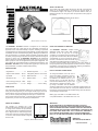
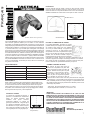
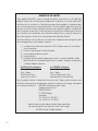
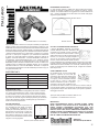
The BUSHNELL TACTICAL binocular is designed for the military/law
enforcement eld, but is also ideal for any demanding environment or
application where rock-solid durability is required. Featuring a liquid-lled
compass built into the viewing optics (model 280750), compass swing stops
immediately due to an advanced damping design. Bearings are called out in
easy-to-read precise 1° increments, ideal for navigation and locating objects
accurately. A range-nding scale allows the viewer to estimate the range to
objects of a known size. The BUSHNELL TACTICAL is fully waterproof/
fogproof and shock protected with suregrip rubber armoring, and has roll-
down eyecups for use with sunglasses and prescription eyeglasses. The
optics feature fully multi-coated lenses for excellent light transmission. The
BUSHNELL TACTICAL comes complete with rugged nylon case and neck
strap. Built to last, it includes a lifetime limited warranty.
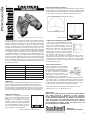
SPECIFICATIONS
Magnication.............................7 x Relative brightness....................51
Objective lens diameter......50 mm Interpupillary distance...60~78 mm
Eye Relief...........................17 mm Maximum width........................7 in
Real eld of view....................6.7 ° Minimum width......................8.5 in
Field of view @ 1000 yds....350 ft. Length......................................6 in
Exit pupil diameter.............7.1 mm Weight.....................48 oz / 1368 g
9200 Cody
Overland Park, KS 66214
Model 280751
Model 280750
Compass (Model 280750 ONLY)
(Model 280751 not shown)
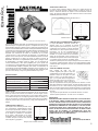
USING THE COMPASS ILLUMINATOR
The BUSHNELL TACTICAL compass model
(#280750) comes with a built-in LED compass
illuminator for use at night and in low light
conditions. The compass housing is located on the
top right side of the binocular, with the two battery
compartments (inc. one for a spare set) found on
the front of the binocular, below the center hinge
shaft. When the ambient light does not permit you
to see the compass heading clearly, press the green power button on
the top compass housing. If the light is dim or does not come on, replace
the batteries. If the light does not operate after replacing the batteries,
please contact the Bushnell dealer nearest you.
HOW TO CHANGE THE BATTERIES
To change the batteries, use a thin coin to
remove the battery compartment cover by
turning it counter-clockwise. Remove the
two batteries. The batteries have a (+) on
the front and a (-) on the back. Be sure to
insert the new batteries with (+) signs in the
same direction. Replace the battery cover
by turning it clockwise. The two batteries
should be replaced at the same time. The batteries should be taken out
if the binoculars will not be used for a long time. Batteries left in the
binocular for prolonged periods of time without being used may leak and
cause damage to the binocular.
Battery Type: Two LR44 1.5 volt alkaline button cell
or equivalent batteries: 1.5v alkaline A76 / G13 / 157
Battery
Compartment
Spare Battery
Storage
Lit#: 98-0773/05-06

2
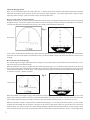
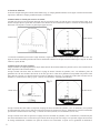
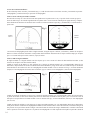
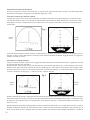
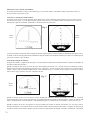
About The Ranging Reticle
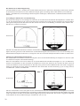
There are vertical and horizontal lines on the reticle (Fig. 1). Each minor division on both vertical and horizontal lines represents
5 mils and each major division represents 10 mils (one circularity angle=6400 mils. (one circular angle equals 1 degree of angle,
equals one minute of angle, equals 60 seconds of angle, and equals 6400 mils.)
How to use the reticle to measure azimuth:
Azimuth of a body is the arc of the horizon intercepted between the north or south point and the foot of the vertical circle passing
through the body. It is reckoned in degrees from either the north or south point clockwise entirely around the horizon. Azimuth of
a current is the direction toward which it is owing, and is usually reckoned from the north point.
A mil’s reticle can measure the azimuth angle, upper and lower angle, distance and size of an object or target. The visual distance
reticle lines can measure the distance of normal object easily on the basis that the object to be measured is at least 2 meters (6 feet)
in height.
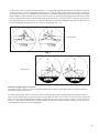
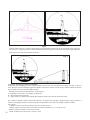
How to measure the azimuth angle:
The azimuth angle is the angle included between two objects to be measured at the horizontal direction of the binocular. (or two
ends of one object at horizontal direction)
When the azimuth of two targets is smaller than the azimuth measuring range (-50~+50 mils) inside the binoculars, aim the scale
line at one end of the reticle at the target then read the value of the scale at which another target was located on the reticle. The value
is the measured azimuth mil. As shown in Fig. 2, the azimuth of the target (tank) is 0-20 mils. The azimuth between the targets (p-p)
is: (280751) 0-65 mils / (280750) 0-80 mils.
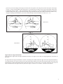
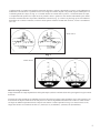
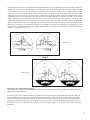
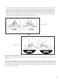
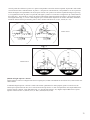
When the azimuth of two targets is bigger than azimuth measuring range (-50~+50 mils) inside the binoculars, an area on the
targets can be selected to make the necessary estimated measurements in a step by step fashion. The sum of the value from each
step is used to obtain the measured azimuth. As shown in g 3, the azimuth of target (cruiser) is 130 mils (60+70=130).
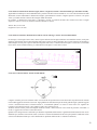
When the azimuth of a target is longer than the azimuth measuring range (-50~+50 mils) inside the binoculars, you can visually
calculate the total azimuth mils by using the vertical line on the reticle by placing the image in a position where the vertical line
splits the image. You will need to take two image readings. Mentally, consider the horizontal with three reference points. Point A
is the 50 mil point on the far left side. Point B is where the vertical line intersects the horizontal line. Point C is the far right 50 mil
Fig. 2
Fig. 1
Model 280751
Model 280750
Model 280751
Model 280750

3
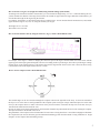
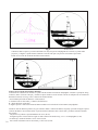
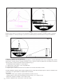
Upper and lower angle measurement:
Upper and lower angle means the angle included between any two targets (or two ends of a target) against the vertical line on
the reticle.
An upper and lower angle measurement is similar to measuring the azimuth. When the upper and lower angle measurement is
very small, aim the cross center of reticle at lower part of the target, read the scale value at the top of the target. The value is the
measured mils of angle included between the upper and lower parts. As shown in Fig. 4, the value of the lower part is 40, the
angle included between the upper and lower parts of the target is: (280751) 0-75 (75mils) / (280750) 0-60 (60 mils).
Fig. 3
point. Now your rst reading on the image will be the mils from point A to B with point A on the far left part of the image
(see Fig. 3). Your second reading will be from point C to point B where point B is now the spot on the image where point
B ended after the rst reading. After calculating the mils for each image, you then can add them together to get the total
azimuth reading. In the (Fig. 3) image below, the ship is longer than the total 100 mils available on the reticle. However, by
doing the foregoing mil calculations, you can now obtain the ship’s total mil azimuth of 130 mils ( 60 + 70 ).
Model 280750
Model 280751

4
When the target’s upper and/or lower limits are larger than the mils on the reticle, it can be measured in steps and the angle
can be obtained by summing up the value of each step. (The process will be similar to the one that is discussed in the linear
measurements section above.)
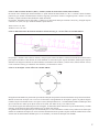
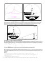
How to use the reticle to measure distance
The distance measurement of a target can be calculated by using the mil reticle. Refer to the example in Fig. 5 above. (Note:
the same concept and formula apply when using the vertical reticle either model Tactical binocular, 280750 reticle only is
shown in Fig.5).
The formula for distance measurement: L(km)=H(m)/w
L= the distance between the observer and the target (in kilometers).
H = the height of the target (in meters)
w=upper and lower angle of azimuth of the target measured with the binocular reticle (mil).
When measuring the distance, rst, estimate the height or width of the target, then measuring upper and lower angle of the
target. Accordingly, you can calculate the distance between the observer and the target using the formula.
For example:
There is a lighthouse whose height is known to be approx. 30 m. (H=30)
The upper and lower angle of the lighthouse as measured against the reticle in Fig. 5 is 0 – 60 mils (w=60)
So, using the formula: L=H/w=30/60=0.5 km
Therefore: the distance between the observer and the lighthouse is 0.5 km.
Fig. 4
Model 280751
Model 280750
Fig. 5

5
How to measure a target’s size (height and width) using azimuth readings (both models)
According to the formula for distance measurement, you can calculate the height using: H = D x w. When measuring the size,
you rst estimate the distance to the target, then measure the azimuth or upper and lower angle. With these measurements, you
can calculate the height of the target using the formula.
For example: the distance is 0.6km between the observer and the target. You can measure that the azimuth is 60 (0-60) and the
upper and lower angle is 30 (0-30). So, using the formula you can get:
The height: H=0.6 x 30=18m
The width: h=0.6 x 60=36m
How to measure distance directly using the reticle in ( Fig. 6) NOTE: Model 280751 ONLY
For example, if the target is 2 meters in height, place the lower part of the target at the horizontal line on the reticle with the
upper top part of the target against the angled scale line. The reading on the top of the target, where the top of the target or image
touches the top of the angled scale line, is the distance between the target and the observer.(line value: 100m) As shown in Fig.
6, the distance between the target and the observer is 550m.
How to use the compass NOTE: Model 280750 ONLY
The azimuth angle can be also measured through the compass built into the right half of the body . It shows the azimuth of
the object vis-à-vis the observer. Each graduation of the compass equals one degree of angle. When the object lies in the north
from you, the compass shows 0°.And it will increase when you turn clockwise. 90°means the object lies in the east from you,
180°means the south and 270°means the west.
In order to insure precise angle measurements, the binoculars should be kept horizontal and level when reading the compass.
The object should lie in the middle of the reticle.
The graduations of the compass need to be illuminated for convenient viewing when there is not sufcient daylight to illuminate
the compass dial. (Do not use the battery operated internal illuminating system when the outside viewing conditions are bright
enough to see the compass dial and marking clearly.)
Fig. 6
Fig. 7

6
LIFETIME LIMITED WARRANTY
Your Bushnell® product is warranted to be free of defects in materials and workmanship
for the lifetime of the original owner. The Lifetime Limited Warranty is an expression of
our confidence in the materials and mechanical workmanship of our products and is your
assurance of a lifetime of dependable service. In the event of a defect under this warranty,
we will, at our option, repair or replace the product, provided that you return the product
postage prepaid. This warranty does not cover damages caused by misuse, improper
handling, installation, or maintenance provided by someone other than a Bushnell
Authorized Service Department.
Any return in the U.S. or Canada made under this warranty must be accompanied by the
items listed below:
1) A check/money order in the amount of $10.00 to cover
the cost of postage and handling
2) Name and address for product return
3) An explanation of the defect
4) Proof of Purchase
5) Product should be well packed in a sturdy outside shipping carton, to
prevent damage in transit, with return postage prepaid to the address
listed below:
IN U.S.A. Send To: IN CANADA Send To:
Bushnell Outdoor Products Bushnell Outdoor Products
Attn.: Repairs Attn.: Repairs
8500 Marshall Drive 25A East Pearce Street, Unit 1
Lenexa, Kansas 66214 Richmond Hill, Ontario L4B 2M9
For products purchased outside the United States or Canada please contact your local
dealer for applicable warranty information. In Europe you may also contact Bushnell at:
BUSHNELL Performance Optics Gmbh
European Service Centre
MORSESTRASSE 4
D- 50769 KÖLN
GERMANY
Tél: +49 (0) 221 709 939 3
Fax: +49 (0) 221 709 939 8
This warranty gives you specific legal rights.
You may have other rights which vary from country to country.
©2006 Bushnell Outdoor Products
Page is loading ...
Page is loading ...
Page is loading ...
Page is loading ...
Page is loading ...
Page is loading ...
Page is loading ...
Page is loading ...
Page is loading ...
Page is loading ...
Page is loading ...
Page is loading ...
Page is loading ...
Page is loading ...
Page is loading ...
Page is loading ...
Page is loading ...
Page is loading ...
Page is loading ...
Page is loading ...
Page is loading ...
Page is loading ...
Page is loading ...
Page is loading ...
Page is loading ...
Page is loading ...
Page is loading ...
Page is loading ...
Page is loading ...
Page is loading ...

37
©2006 Bushnell Outdoor Products
www.bushnell.com
FCC Note:
is equipment has been tested and found to comply with the limits for a
Class B digital device, pursuant to Part 15 of the FCC Rules. ese limits
are designed to provide reasonable protection against harmful interference
in a residential installation. is equipment generates, uses and can radiate
radio frequency energy and, if not installed and used in accordance with
the instructions, may cause harmful interference to radio communications.
However, there is no guarantee that interference will not occur in a particular
installation. If this equipment does cause harmful interference to radio or
television reception, which can be determined by turning the equipment
o and on, the user is encouraged to try to correct the interference by one
or more of the following measures:
· Reorient or relocate the receiving antenna.
· Increase the separation between the equipment and receiver.
· Connect the equipment into an outlet on a circuit
dierent from that to which the receiver is connected.
· Consult the dealer or an experienced radio/TV
technician for help.
Shielded interface cable must be used with the equipment in order to
comply with the limits for a digital device pursuant to Subpart B of Part 15
of FCC Rules.
Specications and designs are subject to change without any notice or
obligation on the part of the manufacturer.
-
 1
1
-
 2
2
-
 3
3
-
 4
4
-
 5
5
-
 6
6
-
 7
7
-
 8
8
-
 9
9
-
 10
10
-
 11
11
-
 12
12
-
 13
13
-
 14
14
-
 15
15
-
 16
16
-
 17
17
-
 18
18
-
 19
19
-
 20
20
-
 21
21
-
 22
22
-
 23
23
-
 24
24
-
 25
25
-
 26
26
-
 27
27
-
 28
28
-
 29
29
-
 30
30
-
 31
31
-
 32
32
-
 33
33
-
 34
34
-
 35
35
-
 36
36
-
 37
37


Ask a question and I''ll find the answer in the document
Finding information in a document is now easier with AI
in other languages
- italiano: Bushnell 280750 Manuale utente
- français: Bushnell 280750 Manuel utilisateur
- español: Bushnell 280750 Manual de usuario
- Deutsch: Bushnell 280750 Benutzerhandbuch
- português: Bushnell 280750 Manual do usuário
Related papers
-
Bushnell Marine 7x50 Binoculars w/Digital Compass 137570 Owner's manual
-
-
-
-
-
-
-
-
-
Other documents
-
Barco OverView cDG67-DL Owner's manual
-
Barska Deep Sea 7x50 Owner's manual
-
Bresser 1866840 Owner's manual
-
-
 Plastimo RESCUE 7x50 Instructions For Use And Maintenance Manual
-
Tasco Binocular w/Compass, Time & Temperature Display 1025CTT User manual
-
Newcon Optik AN 8x30M22 User manual
-
Celestron Oceana 71189-B User manual
-
-
Steiner 202102317 Ranger LRF 10×42 User manual
