
SINGLE PACKAGE
AIR CONDITIONERS
MODELS
P1142A3
P1148A1
P1060A1
INSTALLATION INSTRUCTIONS
Manual : 2100-324B
Supersedes: 2100-324A
File: Volume II Tab 10
Date: 04-01-02
Bard Manufacturing Company
Bryan, Ohio 43506
Since 1914 . . . Moving ahead, just as planned
© Copyright 2002

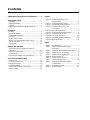
Contents
Getting Other Informations and Publications ........ 1
General Instructions
Important ................................................................ 4
Shipping Damage .................................................... 4
General ................................................................ 4
Field-Installed Heater Packages (Optional) ............. 4
Installation
Location ................................................................ 6
Typical Installations .................................................. 6
Condensate Drain Trap ............................................ 9
Air Filters ................................................................ 9
Wiring – Main Power.............................................. 10
Wiring – 24V Low Voltage Control Circuit .............. 10
Transformer Taps................................................... 10
Thermostats........................................................... 10
Start Up and Operation
Three Phase Scroll Compressor Start Up
Information..............................................................11
Sequence of Operation...........................................11
Start Up Notes ........................................................11
High Pressure Switch and Lockout Relay ...............11
Service and Troubleshooting
Service Hints ......................................................... 12
Pressure Service Ports .......................................... 12
Refrigerant Charge ................................................ 12
Fan Blade Settings................................................. 12
Suction and Discharge Tube Brazing..................... 12
Pressure Table ....................................................... 13
Figures
Figure 1 Prefabricated Rood Curb
Specifications .......................................... 5
Figure 2 Field Fabricated Curbing ......................... 5
Figure3 Elevated Mounting Platforms .................. 7
Figure 4 Airflow and Service Access
Clearances .............................................. 7
Figure 5 Roof Top Application ............................... 8
Figure 6 Slab Mounting at Ground Level ............... 8
Figure 7 Condensate Drain Trap ........................... 9
Figure 8 Low Voltage Wiring ............................... 10
Figure 9 Fan Blade Setting Dimensions .............. 12
Figure 10 Brazing Diagram ................................... 13
Tables
Table 1 Electrical Data......................................... 2
Table 2 Optional Field Installed Heater
Packages ................................................ 2
Table 3 Optional Field Installed Heater Table....... 3
Table 4 Maximum ESP of Operation ................... 4
Table 5 Rated CFM and Rated ESP.................... 6
Table 5A ESP in Inches H
2
O .................................. 6
Table 6 Air Filter Area and Size ........................... 9
Table 7 Thermostat Wire Size ........................... 10
Table 8 Wall Thermostat and Subbase
Combinations ........................................ 10
Table 9 Refrigerant Charge ............................... 12
Table10 Pressure Table ...................................... 13

Manual 2100-324
Page 1
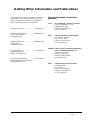
Getting Other Information and Publications
These publications can help you install the air conditioner
or heat pump. You can usually find these at your local
library or purchase them directly from the publisher. Be
sure to consult current edition of each standard.
National Electrical Code........................... ANSI/NFPA 70
Standard for the Installation .................. ANSI/NFPA 90A
of Air Conditioning and
Ventilating Systems
Standard for Warm Air .......................... ANSI/NFPA 90B
Heating and Air
Conditioning Systems
Load Calculation for ................................ ACCA Manual J
Residential Winter and
Summer Air Conditioning
Duct Design for Residential....................ACCA Manual D
Winter and Summer Air Conditioning
and Equipment Selection
For more information, contact these
publishers:
ACCA Air Conditioning Contractors of America
1712 New Hampshire Ave. N.W.
Washington, DC 20009
Telephone: (202) 483-9370
Fax: (202) 234-4721
ANSI American National Standards Institute
11 West Street, 13th Floor
New York, NY 10036
Telephone: (212) 642-4900
Fax: (212) 302-1286
ASHRAE American Society of Heating, Refrigerating,
and Air Conditioning Engineers, Inc.
1791 Tullie Circle, N.E.
Atlanta, GA 30329-2305
Telephone: (404) 636-8400
Fax: (404) 321-5478
NFPA National Fire Protection Association
Batterymarch Park
P.O. Box 9101
Quincy, MA 02269-9901
Telephone: (800) 344-3555
Fax: (617) 984-7057

Manual 2100-324
Page 2
ledoM
detaR
&stloV
sesahP
gnitarepO
egatloV
egnaR
mumixaM
spmAtinU
mumixaM
lanretxE
rosesuF
.krB.tkC
muminiM
tiucriC
yticapmA
dleiF
rewoP
gniriW
dnuorG
eziSeriW
A.tkCA.tkCA.tkCA.tkC
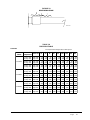
3A2411P1-802/032352-7912.425492801
1A8411P1-802/042352-7911.620563801
B-1A8411P3-802/032352-7818.815332801
C-1A8411P3-064605-4145.802312121
1A0601P1-802/032352-7919.330624801
B-1A0601P3-802/032352-7817.325482801
C-1A0601P3-064605-4142.1102412121
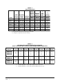
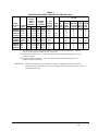
TABLE 1
ELECTRICAL DATA
Q
R
R
TABLE 2
OPTIONAL FIELD INSTALLED HEATER PACKAGES
ONLY TO BE USED WITH THE AIR CONDITIONING MODELS INDICATED
S – Standard application – Heater volts and phase same as basic unit
A – Alternate application – Heater volts and phase different from basic unit
egakcaPretaeH
.oNledoM
dnastloV
esahP3A2411P1A8411PB-1A8411PC-1A8411P1A0611PB-1A0611PC-1A0611P
50A-BP5HE
01A-BP5HE
51A-BP5HE
02A-BP5HE
1/042
S
S
S
S
S
S
S
S
A
A
A
A
A
A
A
A
S
S
S
S
A
A
A
A
A
A
A
A
90B-BP5HE
51B-BP5HE
81B-BP5HE
3/042
A
A
A
S
S
S
A
A
A
A
A
A
S
S
S
A
A
A
9OC-BP5HE
51C-BP5HE
81B-BP5HE
3/084
A
A
A
A
A
A
S
S
S
A
A
A
A
A
A
S
S
S
Maximum time delay fuse or HACR type circuit breaker.
75 degree C cooper wire size, basic unit only.
Q
R

Manual 2100-324
Page 3
retaeH
ledoM.gkP
.oN
stloVtinU
esahP
&WK.rtH
yticapaC
@
ro(V042
fiV084
)elbacilppa
&WK.rtH
yticapaC
@
stloV802
@
V042
saV084ro
elbacilppa
spmA.rtH
retaeH
lanretnI
sesuF
BtiucriC
.oN
dleiF
.stkC
muminiM
tiucriC
yticapmA
mumixaM
tnerrucrevO
noitcetorP
dleiF
rewoP
gniriW
dnuorG
eriW
eziSWKHUTBWKHUTB
50A-BP5HE
01A-BP5HE
51A-BP5HE
02A-BP5HE
1-802/042
1-802/042
1-802/042
1-802/042
5
01
51
02
001,71
001,43
002,15
002,86
57.3
05.7
52.11
00.51
008,21
000,62
004,83
002,15
8.02
7.14
5.26
2.38
06/03
06/06
1
1
1
1
62
35
97
401
03
06
08
011
01
6
4
2
01
01
8
6
90B-BP5HE
51B-BP5HE
81B-BP5HE
3-802/042
3-802/042
3-802/042
9
51
81
007,03
002,15
004,16
57.6
52.11
05.31
000,32
004,83
001,64
7.12
2.63
4.34
1
1
1
82
64
55
03
05
06
01
8
6
01
01
01
90C-BP5HE
51C-BP5HE
81C-BP5HE
3/064
3/064
3/064
9
51
81
007,03
002,15
004,16
57.6
52.11
05.31
000,32
004,83
001,64
8.01
0.81
7.12
1
1
1
51
32
82
51
52
03
41
01
01
41
01
01
TABLE 3
OPTIONAL FIELD-INSTALLED ELECTRIC HEATER TABLE
Q
R
S
Q
R
S
Time delay fuses or “HACR” type circuit breakers must be used for 60 and smaller sizes. Standard
fuses or circuit breakers are suitable for sizes 70 and larger.
Based on wire suitable for 75° C. Other wiring materials must be rated for marked “Minimum Circuit
Ampacity” or greater.
Based upon Table 250-95 of N.E.C. 1993. See electrical data for basic heat pump for Circuit A
wiring specification requirements.
IMPORTANT: While this electrical data is presented as a guide, it is important to electrically connect
properly size fuses and conductor wires in accordance with the National Electrical Code and
all existing local codes.

Manual 2100-324
Page 4
GENERAL INSTRUCTIONS
IMPORTANT
The equipment covered in this manual is to be installed by
trained, experienced service and installation technicians.
All duct work, supply and return ducts, must be properly
sized for the design air flow requirement of the equipment.
ACCA is an excellent guide to proper sizing. All duct
work or portions thereof not in the conditioned space
should be properly insulated in order to both conserve
energy and prevent condensation or moisture damage.
SHIPPING DAMAGE
Upon receipt of equipment, the carton should be checked
for external signs of shipping damage. If damage is found,
the receiving party must contact the last carrier
immediately, preferably in writing, requesting inspection
by the carrier’s agent.
GENERAL
The refrigerant system is completely assembled and
charged. All internal wiring is complete.
The unit is designed for use with or without duct work.
Flanges are provided for attaching the supply and return
ducts.
These instructions explain the recommended method to
install the air cooled self-contained unit and the electrical
wiring connections to the unit.
These instructions and any instructions packaged with any
separate equipment required to make up the entire heat
pump system should be carefully read before beginning the
installation. Note particularly “Starting Procedure” and
any tags and/or labels attached to the equipment.
While these instructions are intended as a general
recommended guide, they do not supersede any national
and/or local codes in any way. Authorities having
jurisdiction should be consulted before the installation is
made.
Refer to the electrical data shown on pages 2 and 3 for
proper application information on all available heater
combinations and what units they can be used with. It also
shows the applicable circuit ampacities, fuse size, and wire
size for each heater combination.
Refer to the installation instructions packed with the heater
for details on how to insert it into the basic unit.
FIELD INSTALLED HEATER PACKAGES
(OPTIONAL)
These packaged heat pumps are manufactured without
supplementary electric heaters. Supplementary heaters
EH5PB series (to fit P1142A3, P1148A1, and P1160A1)
are available for simple, fast, field installation.
A separate field power circuit is required for the
supplementary heaters.
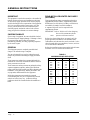
IMPORTANT: Refer to Table 4 and 5 when designing
duct work for maximum available
static pressure with heater installed.
TABLE 4
MAXIMUM ESP OF OPERATION
3A2411P1A8411P1A0601P
00A
50A
01A
51A
02A
05.
05.
05.
04.
04.
05.
05.
05.
05.
05.
05.
05.
05.
05.
05.
00B
90B
51B
81B
---
---
---
---
05.
05.
05.
05.
05.
05.
05.
05.
00C
90C
51C
81C
---
---
---
---
05.
05.
05.
05.
05.
05.
05.
05.

Manual 2100-324
Page 5
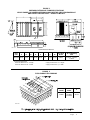
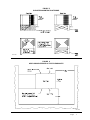
FIGURE 1
PREFABRICATED ROOF CURB SPECIFICATIONS
HEAVY GAUGE GALVANIZED WITH WOOD NAILING STRIP, WELDED/LEAKPROOF
ONE PIECE CONSTRUCTION – READY TO INSTALL
MIS-1177
FIGURE 2
FIELD FABRICATED CURBING
MIS-1178
CURB AND ROOF DETAILS
*
Duct Sizing Information
Return Air Dimension “C” is length Supply Air Dimension “C” is length
Return Air Dimension “H” is width Supply Sir Dimension “J” is width
fooR
bruCAB*CDEF *J*H
dooHfooR
ledoM
gninoitidnoCriA
stinU
400-24098/3-288/1-448/1-148/3-838/3-53444/3-418/1-9106EHR
,1A8411P,3A2411P
1A0601P
dooHfooR
ledoM
tinU
ledoM
E
06EHR
3A2411P
1A8411P
1A0601P
8/7-44

Manual 2100-324
Page 6
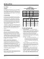
INSTALLATION
LOCATION
GENERAL
The unit must be located outside, or in a well ventilated
area. It must not be in the space being heated or cooled. A
sound absorbing material should be considered if the unit
is to be installed in such a position or location that might
cause transmission of sound or vibration to the living area
or adjacent buildings.
SLAB MOUNTING
In areas where winter temperatures DO NOT go below
32° F for periods over twelve hours, the unit may be slab
mounted at grade level. When installing unit at grade
level, install on a concrete slab at least four inches above
finished grade level. Slab should have a slope tolerance
away from the building structure of at lease 1/4 inch per
foot, while being level from side to side. Place slab in a
location where runoff water from higher ground will not
collect around unit. See Figure 3.
A minimum of 18 inches should be provided between the
coil inlet and any building surfaces. Provide at least four
feet between coil outlet and any building wall, fences or
other vertical structures. Provide a minimum of three feet
clearance on the service access side of the unit. See
Figure 4
ROOF MOUNTING
When a unit is installed in areas where low ambient
temperatures or strong winter winds exist, it should be
placed for prevailing winter winds are not in direct line
with the outdoor coil. If this is not possible, a wind barrier
should be constructed. Place barrier 24 inches from the
coil inlet side of the unit and in the direction of prevailing
winds. Size barrier at least the same height and width as
the unit. This may be necessary on ground level
installations, also. See Figure 5.
WINTER INSTALLATION BELOW 32°F
In areas where winter conditions go below 32°F for
extended periods, the unit must be elevated above the
mounting surface to prevent snowfall or ice accumulation
from interfering with the operation of the unit. A
minimum of twelve inch elevation is recommended, while
greater elevation may be required for areas of high snow
accumulation. Poured concrete, steel framework, brick,
cement block, etc., can be utilized to construct a suitable
raised mounting platform. See Figure 6.
DUCT WORK
Refer to Tables 4, 5 and 5A when designing duct work for
maximum static pressure available with the specific model
and heater package being installed.
TABLE 5A
TYPICAL INSTALLATIONS
1.
ROOF MOUNTED
– The unit is mounted on a
sturdy base on the roof of the building. Return air to
the unit is brought through a single return grille (grilles
with built-in filters are best since they enable easy
access for filter changing). Return air ducts are
attached to the lower section of the front panel.
Supply air is brought from the unit to attic duct work
or to a furred down hall. Supply air duct is attached to
the top of the front panel.
CAUTION: All outdoor duct work must be
thoroughly insulated and weatherproofed. All
attic duct work must be thoroughly insulated.
Two inch thick insulation with suitable vapor
barrier is recommended for both outdoor and
attic runs.
In roof top installation, as in all installations, the air
conditioner must be level from side to side. However,
the unit should have a pitch along the length to assure
complete external drainage of precipitation and of
defrost condensate.
2.
CRAWL SPACE
– Duct work installed in crawl
space must be well insulated and provided with a
vapor barrier. In addition, the crawl space must be
thoroughly ventilated and provided with a good vapor
barrier as a ground cover. It is most desirable to install
the unit will be outdoors rather than inside the crawl
space, so that it will be readily accessible for service.
PSE
sehcnI
H
2
O
3A2411P
12411HP
teW/yrD
1A8411P
8401HP
teW/yrD
1A0601P
0601HP
teW/yrD
0
1.
2.
3.
4.
5.
5261/0561
5251/0551
0041/5341
0131/0431
0121/0321
0011/0211
0291/0591
0381/0681
0571/0871
0661/0861
0551/0851
0841/0051
0581/0581
0871/0081
0071/5271
5261/0661
0451/0851
5741/0051
TABLE 5
RATED CFM AND
EXTERNAL STATIC PRESSURE (ESP)
WET COIL (COOLING)
ledoM
detaR
MFC
detaR
PSE
dednemmoceR
egnaRwolFriA
3A2411P004102.MFC0451-0621
1A8411P055104.MFC0071-0041
1A0601P007102.MFC0781-0351

Manual 2100-324
Page 7
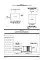
FIGURE 3
ELEVATED MOUNTING PLATFORMS
MIS-1183
MIS-1185
FIGURE 4
AIRFLOW AND SERVICE ACCESS CLEARANCES

Manual 2100-324
Page 8
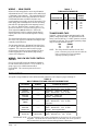
FIGURE 5
ROOF TOP APPLICATION
(MAY ALSO BE REQUIRED FOR GROUND LEVEL INSTALLATIONS.)
MIS-1176
FIGURE 6
SLAB MOUNTING AT GROUND LEVEL
(ABOVE 32° F OUTSIDE TEMPERATURE)
MIS-1184

Manual 2100-324
Page 9
FIGURE 7
CONDENSATE DRAIN TRAP
MIS-136
3.
SLAB MOUNTED AT GROUND LEVEL
– This
type installation is ideal for homes with a slab floor
construction where a roof mounted unit is not desired.
The supply and return duct work can be run through a
furred closet space.
4.
THROUGH THE WALL
– This type installation
requires a suitable framework to be fabricated capable
of withstanding the unit weight. Normally the unit will
be insulated so as to minimize supply and return duct
work.
5.
OTHER INSTALLATIONS
– Many other
installations are possible with the packaged air
conditioner. No matter what the installation, always
consider the following facts:
A. Insure that the discharge air is not obstructed inany
way so as to cause operation difficulties.
B. The indoor coil drain pan is equipped with a
coupling that must be piped through a condensate
drain trap to a suitable drain.
C. Always mount the unit is such a position that it
may be easily reached for servicing and
maintenance.
D. Insure that the unit is clear so that proper air flow
over the outdoor coil will be maintained.
If this unit is operated in cooling below a 65° outdoor
ambient temperature, the installation of low ambient
controls (CMA-6) to unit is required.
CONDENSATE DRAIN TRAP
It is very important to provide a trap in the condensate
drain line to allow a positive liquid seal in the line and
assure correct drainage from the coil condensate pan.
Install condensate drain trap shown in Figure 7. Use drain
connection size or larger. Do not operate unit without
trap. Unit must be level or slightly inclined toward drain.
With a trap installed on a unit located in an unconditioned
area, water in the trap may freeze. It is recommended that
the trap material be of a type that will allow for expansion
of water when it freezes.
AIR FILTERS
Air filters for the return air side of the system are not
provided as part of these models, and must be field
supplied and installed as part of the final installation.
Prior thought should be given to return air location and
placement of the air filter(s). The air filter(s) must be of
adequate size and readily accessible to the operator of the
equipment. Filters must be adequate in size and properly
maintained for proper operation. If this is not done,
excessive energy use, poor performance, and multiple
service problems will result. It is impossible to oversize
air filters. Generous sizing will result in cleaner air and
coils as well as lower operating costs and extend the time
between required changes. Table 6 shows minimum filter
areas and recommended filter sizes. Actual filter sizes can
vary with the installation due to single or multiple returns
utilizing a filter/grille arrangement or being placed
immediately ahead of the indoor coil face in the return air
duct.
TABLE 6
RECOMMENDED FILTERS
NOTE: If roof hood accessory is to be used, information
on air filters may be found under that heading
in this manual. Air filters are supplied as part
of that package.
ledoM
retliFmuminiM
saerA
dednemmoceR
eziS
3A2411P
1A8411P
1A0601P
sehcnierauqs806
)teeferauqs26.4(
1x02x61)2(

Manual 2100-324
Page 10
TABLE 7
THERMOSTAT WIRE SIZE
AVremrofsnarTALFeguaGeriW
mumixaM
ecnatsiD
teeFnI
553.2
02
81
61
41
21
54
06
001
061
052
TABLE 8
WALL THERMOSTAT AND SUBBASE COMBINATIONS
tatsomrehTesabbuSserutaeFetanimoderP
200-3048
1113F78T
300-4048
0221A935Q
yrucreM,loocegats1,taehegats1
otua-no:naFlooc-ffo-taeH:metsyS
140-3048
9941C4308T
——
yrucreM,loocegats1,taehegats1
otua-no:naFlooc-ffo-taeH:metsyS
940-3048
083-39F1
——
loocegats2,taehegats2
elbammargorPcinortcelE
340-3048
002MC
——
yrucreM,loocegats1,taehegats1
otua-no:naFlooc-ffo-taeH:metsyS
noitcApanS
840-3048
3131C0048T
——
yrucreM,loocegats1,taehegats1
otua-no:naFlooc-ffo-taeH:metsyS
elbammargorP-noNcinortcelE
910-3048
0671C478T
210-4048
1001A476Q
yrucreM,loocegats1,taehegats2
otua-no:naFlooc-otua-taeh:metsyS
TRANSFORMER TAPS
230/208V, 1 phase and 3 phase equipment employ dual
primary voltage transformers. All equipment leaves the
factory wired on 240V tap. For 208V operation, reconnect
from 240V to 208V tap. The acceptable operating voltage
range for the 240 and 208V taps are:
TAP RANGE
240 253 – 216
208 220 – 187
NOTE: The voltage should be measured at the field
power connection point in the unit and while the
unit is operating at full load (maximum
amperage operating condition).
WIRING – MAIN POWER
Refer to the unit rating plate for wire sizing information
and maximum fuse size. Each outdoor unit is marked with
a “Minimum Circuit Ampacity”. This means that the field
wiring used must be sized to carry that amount of current.
If field installed heaters are added to the basic unit, a
second separate power supply circuit will be required. The
heater rating plate located adjacent to the basic unit rating
plate will show the appropriate circuit ampacity fuse size,
etc. (Also see “Electrical Data” on pages 2 and 3.) All
models are suitable for connection with copper wire only.
These instructions must be adhered to. Refer to the
National Electrical Code for complete current carrying
capacity data on the various insulation grades of wiring
material.
The electrical specifications on page 2 and 3 lists fuse and
wire sizes (75°F copper) for all models including the most
commonly used heater sizes.
The unit rating plate lists a “Maximum Time Delay Fuse”
or “HACR” type circuit breaker that is to be used with the
equipment. The correct size must be used for proper
circuit protection and also to assure that there will be no
nuisance tripping due to the momentary high starting
current of the compressor.
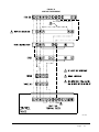
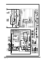
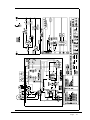
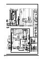
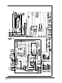
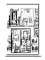
WIRING – 24V LOW VOLTAGE CONTROL
CIRCUIT
Five (5) wires should be run from thermostat subbase to
the 24V terminal board in the unit. A five conductor, 18
gauge copper, color-coded thermostat cable is
recommended. The connection points are shown in
Figure 8.
THERMOSTATS
See specific wiring information for the different models, heater KWs, and voltages on pages 14 through 17.
IMPORTANT NOTE: Only the thermostat and subbase combinations as shown above will work with this
equipment. The thermostat and subbase MUST be matched, and correct operation
can be assured only by proper selection and application of these parts.

Manual 2100-324
Page 11
FIGURE 8
LOW VOLTAGE WIRING
MIS-1180

Manual 2100-324
Page 12
START UP AND OPERATION
THREE PHASE SCROLL COMPRESSOR
START UP INFORMATION
Scroll compressors, like several other types of
compressors, will only compress in one rotational
direction. Direction of rotation is not an issue with single
phase compressors since they will always start and run in
the proper direction.
However, three phase compressors will rotate in either
direction depending upon phasing of the power. Since
there is a 50-50 chance of connecting power in such a way
as to cause rotation in the reverse direction, verification of
proper rotation must be made. Verification of proper
rotation direction is made by observing that suction
pressure drops and discharge pressure rises when the
compressor is energized. Reverse rotation also results in
an elevated sound level over that with correct rotation, as
well as, substantially reduced current draw compared to
tabulated values.
Verification of proper rotation must be made at the time
the equipment is put into service. If improper rotation is
corrected at this time there will be no negative impact on
the durability of the compressor. However, reverse
operation for over one hour may have a negative impact on
the bearing due to oil pump out.
NOTE: If compressor is allowed to run in reverse
rotation for several minutes the compressor’s
internal protector will trip.
All three phase ZR*3 compressors are wired identically
internally. As a result, once the correct phasing is
determined for a specific system or installation, connecting
properly phased power leads to the same Fusite terminals
should maintain proper rotation direction.
The direction of rotation of the motor may be changed by
reversing any two line connections to the unit.
SEQUENCE OF OPERATION
COOLING
– Circuit R-Y makes at thermostat pulling in
compressor contactor starting the compressor and outdoor
motor. The G (indoor motor) circuit is automatically
completed on any call for cooling operation, or can be
energized by manual fan switch on subbase for constant air
circulation.
HEATING
– A circuit R-W1 is completed on each
heating cycle energizing electric heat if so equipped.
START UP NOTES
For improved start up performance, wash the indoor coil
with dishwasher detergent
COMPRESSOR CONTROL MODULE
The compressor control is an anti-short cycle/lockout timer
with high and low pressure switch monitoring and alarm
output.
ADJUSTABLE DELAY-ON-MAKE AND BREAK
TIMER
On a call for compressor operation the delay-on-make
period begins which will be 10% of the delay-on-break
setting. When the delay-on-make is complete and the high
pressure switch (and low pressure switch if employed) is
closed, the compressor contactor is energized. Upon
shutdown the delay-on-break timer starts and prevents
restart until the delay-on-break and delay-on-make periods
have expired.
HIGH PRESSURE SWITCH AND LOCKOUT
SEQUENCE (Standard Feature)
If the high pressure switch opens, the compressor
contactor will de-energize immediately. The lockout timer
will go into a soft lockout and stay in soft lockout until the
high pressure switch closes and the delay-on-make time
has expired. If the high pressure switch opens again in this
same operating cycle the unit will go into manual lockout
condition and the alarm circuit will energize. Recycling
the wall thermostat resets the manual lockout.
LOW PRESSURE SWITCH, BYPASS, AND
LOCKOUT SEQUENCE
NOTE: The low pressure switch is an optional control
and the bypass and lockout sequence are part of
the standard compressor control module.
If the low pressure switch opens for more that 120
seconds, the compressor contactor will de-energize and go
into a soft lockout. Regardless the state of the low
pressure switch, the contactor will reenergize after the
delay-on-make time delay has expired. If the low pressure
switch remains open or opens again for longer than 120
seconds the unit will go into manual lockout condition and
the alarm circuit will energize. Recycling the wall
thermostat resets the manual lockout.

Manual 2100-324
Page 13
ALARM OUTPUT
Alarm terminal is output connection for applications
where alarm signal is desired. This terminal is powered
whenever compressor is locked out due to HPC or LPC
sequences as described.
NOTE: Both high and low pressure switch controls are
inherently automatic reset devices. The high
pressure switch and low pressure switch cut out
and cut in settings are fixed by specific air
conditioner or heat pump unit model. The
lockout features, both soft and manual, are a
function of the Compressor Control Module.
ADJUSTMENTS
ADJUSTABLE DELAY-ON-MAKE AND
DELAY-ON-BREAK TIMER
The potentiometer is used to select Delay-on-Break time
from 30 seconds to 5 minutes. Delay-on-Make (DOM)
timing on power-up and after power interruptions is equal
to 2 minutes plus 10% of Delay-on-Break (DOB) setting:
0.5 minute (30 seconds) DOB = 123 second DOM
1.0 minute (60 seconds) DOB = 126 second DOM
2.0 minute (120 seconds) DOB = 132 second DOM
3.0 minute (160 seconds) DOB = 138 second DOM
4.0 minute (240 seconds) DOB = 144 second DOM
5.0 minute (300 seconds) DOB = 150 second DOM

Manual 2100-324
Page 14
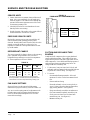
FAN BLADE SETTINGS
Shown in Figure 9 are the correct fan blade setting
dimensions for proper air delivery across the outdoor coil.
Any service work requiring removal or adjustment in the
fan and/or motor area will require that the dimensions
below be checked and blade adjusted in or out on the
motor shaft accordingly.
FIGURE 9
FAN BLADE SETTING DIMENSIONS
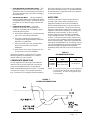
SUCTION AND DISCHARGE TUBE
BRAZING
Compliant Scroll compressors have copper plated steel
suction and discharge tubes. These tubes are far more
rugged and less prone to leaks than copper tubes used on
other compressors. Due to different thermal properties of
steel and copper, brazing procedures may have to be
changed from those commonly used.
•
To disconnect: heat joint Areas 2 and 3 slowly and
uniformly until braze material softens and the tube can
be pulled out of suction fitting. (See Figure 10.)
•
To connect:
– Recommended brazing materials: silfos with
minimum 5% silver or silver braze material with
flux.
– Reinsert tube into fitting.
– Heat tube uniformly in Area 1 moving slowly to
Area 2. When joint reaches brazing temperature,
apply brazing material. (See Figure 10.)
– Heat joint uniformly around the circumference to
flow braze material completely around the joint.
– Slowly move torch into Area 3 to draw braze
material into joint. (See Figure 10.)
– Do not overheat joint.
ledoMAnoisnemiD
3A2411P
1A8411P
1A0601P
"57.1
"57.1
"57.1
TABLE 9
The above suction line temperatures are based upon
80°F dry bulb/67°F wet bulb (50% RH) temperature and
rated airflow across the evaporator during cooling cycle.
ledoM
detaR
wolfriA
FeergeD59
DO
erutarepmeT
FeergeD28
DO
erutarepmeT
3A2411P
1A8411P
1A0610P
0041
0551
0071
95-75
75-55
94-74
06-85
16-95
65-45
SERVICE AND TROUBLESHOOTING
SERVICE HINTS
1. Caution homeowner to maintain clean air filters at all
times. Also, not to needlessly close off supply and
return air registers. This reduces air flow through the
system which shortens equipment service life as well
as increasing operating costs.
2. Check all power fuses or circuit breakers to be sure
that they are the correct rating.
3. Periodic cleaning of the outdoor coil to permit full and
unrestricted airflow circulation is essential.
PRESSURE SERVICE PORTS
High and low pressure service ports are installed on all
units so that the system operating pressures can be
observed. Pressure tables can be found in Table 10 in this
manual covering all models on cooling cycle. It is
imperative to match the correct pressure table to the unit
by model number.
REFRIGERANT CHARGE
The correct system R-22 charge is shown on the unit rating
plate. Optimum unit performance will occur with a
refrigerant charge resulting in a suction line temperature
(6” from compressor) as shown in Table 9.

Manual 2100-324
Page 15
TABLE 10
PRESSURE TABLE
COOLING
Air Temperature Entering Outdoor Coil Degrees F
ledoM
riAnruteR
erutarepmeT
erusserP
5708580959001501011511
3A2411P
BD.ged57
BW.ged26
ediSwoL
ediShgiH
07
802
27
322
57
932
77
452
87
172
97
882
08
503
18
423
28
243
BD.ged08
BW.ged76
ediSwoL
ediShgiH
57
312
77
922
08
542
28
162
48
872
58
592
69
313
78
233
88
153
BD.ged58
BW.ged27
ediSwoL
ediShgiH
18
022
38
732
68
452
88
072
09
882
19
503
29
423
49
443
59
363
1A8411P
BD.ged57
BW.ged26
ediSwoL
ediShgiH
37
302
47
712
57
132
67
642
87
462
97
872
08
492
18
213
28
033
BD.ged08
BW.ged76
ediSwoL
ediShgiH
87
802
97
222
18
732
28
252
38
862
48
582
68
203
78
023
88
833
BD.ged58
BW.ged27
ediSwoL
ediShgiH
38
512
58
032
78
542
88
162
78
372
19
592
29
313
39
133
49
053
1A0601P
BD.ged57
BW.ged26
ediSwoL
ediShgiH
56
412
66
032
86
742
96
462
07
482
27
992
47
813
57
633
67
553
BD.ged08
BW.ged76
ediSwoL
ediShgiH
96
912
17
632
27
352
47
172
67
982
77
703
97
623
08
543
28
463
BD.ged58
BW.ged27
ediSwoL
ediShgiH
47
722
67
442
87
262
97
082
18
692
38
813
58
733
68
753
88
773
MIS-1179
FIGURE 10
BRAZING DIAGRAM

Manual 2100-324
Page 16

Manual 2100-324
Page 17

Manual 2100-324
Page 18
Page is loading ...
Page is loading ...
Page is loading ...
-
 1
1
-
 2
2
-
 3
3
-
 4
4
-
 5
5
-
 6
6
-
 7
7
-
 8
8
-
 9
9
-
 10
10
-
 11
11
-
 12
12
-
 13
13
-
 14
14
-
 15
15
-
 16
16
-
 17
17
-
 18
18
-
 19
19
-
 20
20
-
 21
21
-
 22
22
-
 23
23


Bard P1142A3 User manual
- Category
- Heat pumps
- Type
- User manual
Ask a question and I''ll find the answer in the document
Finding information in a document is now easier with AI
Related papers
-
Bard Q48A1 Installationair conditioner User manual
-
-
-
-
-
-
-
Bard CTHAC601-E Installation Instructions Manual
-
-