Generac XD5000E G0068640 User manual
- Category
- Power generators
- Type
- User manual

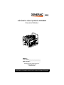
XD5000E Diesel Portable Generator
Owner’s Manual
MODEL:________________________
SERIAL:________________________
DATE PURCHASED:______________
Register your Generac product at:
register.generac.com
1-888-922-8482
SAVE THIS MANUAL FOR FUTURE REFERENCE
000703

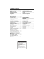
Table of Contents
Section 1 Introduction and Safety 1
Introduction ..................................... 1
Safety Rules .................................... 1
Safety Symbols and Meanings ........ 1
Exhaust and Location Hazards ....... 2
Electrical Hazards ........................... 3
Fire Hazards .................................... 3
Standards Index .............................. 3
Section 2 General Information and
Setup .............................................. 4
Know Your Generator ..................... 5
Emissions Information ..................... 5
Hour Meter ...................................... 6
Connection Plugs ............................ 6
Remove Contents from Carton ....... 7
Assembly ......................................... 7
Battery Installation ........................... 8
Add Engine Oil ................................ 8
Fuel ................................................. 9
Section 3 Operation .................... 10
Operation and Use Questions ....... 10
Before Starting Engine .................. 10
Prepare Generator for Use ............ 10
Grounding the Generator When Used
as a Portable ................................. 10
Know Generator Limits .................. 11
Transporting/Tipping of the Unit .... 11
Starting Pull Start Engines ............ 12
Starting Electric Start Engines ...... 12
Low Oil Pressure Switch ............... 13
Section 4 Maintenance and
Troubleshooting ..........................14
Maintenance ..................................14
.......................................................14
Maintenance Schedule ..................14
Preventive Maintenance ................14
Engine Maintenance ......................14
Engine Oil Recommendations .......14
Battery Replacement (if applicable) 16
Valve Clearance ............................16
Storage ..........................................16
Troubleshooting .............................17
Notes .............................................19
(000394)
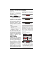
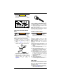
WARNING
Breathing diesel engine exhaust exposes you
to chemicals known to the State of California
to cause cancer and birth defects or other
reproductive harm.
• Always start and operate the engine in a
well-ventilated area.
• If in an enclosed area, vent the exhaust to
the outside.
• Do not modify or tamper with the exhaust
system.
• Do not idle the engine except as necessary.
For more information go to
www.P65Warnings.ca.gov/diesel.

Owner’s Manual for Portable Generator 1
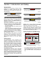
Section 1 Introduction and Safety
Introduction
Thank you for purchasing a Generac Power
Systems Inc. product. This unit has been
designed to provide high-performance, effi-
cient operation, and years of use when main-
tained properly.
If any section of the manual is not understood,
contact your nearest Independent Authorized
Service Dealer (IASD), or contact Generac
Customer Service at 1-888-GENERAC (1-
888-436-3722), or www.generac.com with any
questions or concerns.
The owner is responsible for proper mainte-
nance and safe use of the equipment. Before
operating, servicing or storing this generator:
• Study all warnings in this manual and on
the product carefully.
• Become familiar with this manual and the
unit before use.
• Refer to the Assembly section of the man-
ual for instructions on final assembly proce-
dures. Follow the instructions completely.
Save these instructions for future reference.
ALWAYS supply this manual to any individual
that will use this machine.
The information in this manual is accurate
based on products produced at the time of
publication. The manufacturer reserves the
right to make technical updates, corrections,
and product revisions at any time without
notice.
Safety Rules
The manufacturer cannot anticipate every
possible circumstance that might involve a
hazard. The warnings in this manual, and on
tags and decals affixed to the unit are, there-
fore, not all inclusive. If using a procedure,
work method or operating technique that the
manufacturer does not specifically recom-
mend, verify that it is safe for others. Also
make sure the procedure, work method or
operating technique utilized does not render
the equipment unsafe.
Throughout this publication, and on tags and
decals affixed to the generator, DANGER,
WARNING, CAUTION and NOTE blocks are
used to alert personnel to special instructions
about a particular operation that may be haz-
ardous if performed incorrectly or carelessly.
Observe them carefully. Their definitions are
as follows:
NOTE: Notes contain additional information
important to a procedure and will be found
within the regular text of this manual.
These safety warnings cannot eliminate the
hazards that they indicate. Common sense
and strict compliance with the special instruc-
tions while performing the action or service
are essential to preventing accidents.
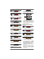
Safety Symbols and Meanings
• If you start to feel sick, dizzy, or weak after
the generator has been running, move to
fresh air IMMEDIATELY. See a doctor, as
you could have carbon monoxide poison-
ing.
(000100a)
WARNING
Consult Manual. Read and understand manual
completely before using product. Failure to
completely understand manual and product
could result in death or serious injury.
(000001)
DANGER
Indicates a hazardous situation which, if not avoided,
will result in death or serious injury.
(000002)
WARNING
Indicates a hazardous situation which, if not avoided,
could result in death or serious injury.
(000003)
CAUTION
Indicates a hazardous situation which, if not avoided,
could result in minor or moderate injury.
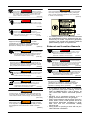
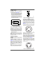
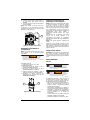
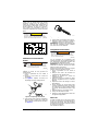
DANGER
Using a generator indoors CAN KILL YOU IN MINUTES.
Generator exhaust contains carbon monoxide. This is
a poison you cannot see or smell.
NEVER use inside a home
or garage, EVEN IF doors
and windows are open.
Only use OUTSIDE and
far away from windows,
doors, and vents.
000657
(000103)
DANGER
Asphyxiation. Running engines produce carbon
monoxide, a colorless, odorless, poisonous gas.
Carbon monoxide, if not avoided,
will result in death or serious injury.

2 Owner’s Manual for Portable Generator
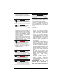
• For safety reasons, it is recommended that
the maintenance of this equipment be per-
formed by an IASD. Inspect the generator
regularly, and contact the nearest IASD for
parts needing repair or replacement.
Exhaust and Location Hazards
• If you start to feel sick, dizzy, or weak after
the generator has been running, move to
fresh air IMMEDIATELY. See a doctor, as
you could have carbon monoxide poison-
ing.
• NEVER run a generator indoors or in a
partly enclosed area such as garages.
• ONLY use outdoors and far away from win-
dows, doors, vents, crawl spaces and in an
area where adequate ventilation is avail-
able and will not accumulate deadly
exhaust gas.
• Using a fan or opening a door will not pro-
vide sufficient ventilation.
(000179b)
DANGER
Asphyxiation. The exhaust system must be properly
maintained. Do not alter or modify the exhaust system
as to render it unsafe or make it noncompliant with
local codes and/or standards. Failure to do so will
result in death or serious injury.
(000104)
DANGER
Electrocution. Water contact with a power source,
if not avoided, will result in death or serious injury.
(000116)
DANGER
Electrocution. Turn utility and emergency
power supplies to OFF before connecting power
source and load lines. Failure to do so will result
in death or serious injury.
(000146)
WARNING
Equipment and property damage. Do not alter
construction of, installation, or block ventilation for
generator. Failure to do so could result in unsafe
operation or damage to the generator.
(000178a)
Asphyxiation. Always use a battery operated carbon
monoxide alarm indoors and installed according to
the manufacturer’s instructions. Failure to do so
could result in death or serious injury.
WARNING
(000250)
WARNING
Equipment and property damage. Do not operate unit on
uneven surfaces, or areas of excessive moisture, dirt, dust
or corrosive vapors. Doing so could result in death, serious
injury, property and equipment damage.
(000111)
WARNING
Moving Parts. Keep clothing, hair, and appendages
away from moving parts. Failure to do so could
result in death or serious injury.
(000108)
WARNING
Hot Surfaces. When operting machine, do not
touch hot surfaces. Keep machine away from
combustables during use. Hot surfaces
could result in severe burns or fire.
(000142a)
Personal injury. Do not insert any object through the
air cooling slots. Generator can start at any time and
could result in death, serious injury, and unit damage.
WARNING
WARNING
Risk of injury. Do not operate or service this machine
if not fully alert. Fatigue can impair the ability to service
this equipment and could result in death or serious
injury.
(000215)
WARNING
Injury and equipment damage. Do not use generator
as a step. Doing so could result in falling, damaged
parts, unsafe equipment operation, and could result
in death or serious injury.
(000216)
000406
(000103)
DANGER
Asphyxiation. Running engines produce carbon
monoxide, a colorless, odorless, poisonous gas.
Carbon monoxide, if not avoided,
will result in death or serious injury.
(000179b)
DANGER
Asphyxiation. The exhaust system must be properly
maintained. Do not alter or modify the exhaust system
as to render it unsafe or make it noncompliant with
local codes and/or standards. Failure to do so will
result in death or serious injury.
(000178a)
Asphyxiation. Always use a battery operated carbon
monoxide alarm indoors and installed according to
the manufacturer’s instructions. Failure to do so
could result in death or serious injury.
WARNING
(000146)
WARNING
Equipment and property damage. Do not alter
construction of, installation, or block ventilation for
generator. Failure to do so could result in unsafe
operation or damage to the generator.

Owner’s Manual for Portable Generator 3
• Point muffler exhaust away from people
and occupied buildings.
Electrical Hazards
• National Electric Code (NEC) requires the
frame and external electrically conductive
parts of the generator be properly con-
nected to an approved earth ground. Local
electrical codes may also require proper
grounding of the generator. Consult with a
local electrician for grounding requirements
in the area.
• Use a ground fault circuit interrupter (GFCI)
in any damp or highly conductive area
(such as metal decking or steel work).
• Once generator has been started outside,
connect electrical loads to extension
cord(s) inside.
Fire Hazards
• Allow at least 5 feet of clearance on all
sides of the generator when operating to
prevent overheating and fire.
• Do not operate the generator if connected
electrical devices overheat, if electrical out-
put is lost, if engine or generator sparks, or
if flames or smoke are observed while unit
is running.
• Keep a fire extinguisher near the generator
at all times.
Standards Index
1. National Fire Protection Association
(NFPA) 70: The NATIONAL ELECTRIC
CODE (NEC) available from www.nfpa.org
2. National Fire Protection Association
(NFPA) 5000: BUILDING CONSTRUC-
TION AND SAFETY CODE available from
www.nfpa.org
3. International Building Code available from
www.iccsafe.org
4. Agricultural Wiring Handbook available
from www.rerc.org, Rural Electricity
Resource Council P.O. Box 309 Wilming-
ton, OH 45177-0309
5. ASAE EP-364.2 Installation and Mainte-
nance of Farm Standby Electric Power
available from www.asabe.org, American
Society of Agricultural & Biological Engi-
neers 2950 Niles Road, St. Joseph, MI
49085
6. CSA C22.2 100-14 Electric motors and
generators for installation and use, in
accordance with the Rules of the Cana-
dian Electrical Code
7. ANSI/PGMA G300 Safety and Perfor-
mance of Portable Generators. Portable
Generator Manufacturer’s Association,
www.pgmaonline.com
IMPORTANT NOTE: This list is not all inclu-
sive. Check with the Authority Having
Jurisdiction (AHJ) for any local codes or
standards which may be applicable to your
jurisdiction.
(000144)
DANGER
Electrocution. Contact with bare wires,
terminals, and connections while generator
is running will result in death or serious injury.
(000104)
DANGER
Electrocution. Water contact with a power source,
if not avoided, will result in death or serious injury.
(000145)
DANGER
Electrocution. In the event of electrical accident,
immediately shut power OFF. Use non-conductive
implements to free victim from live conductor. Apply
first aid and get medical help. Failure to do so will
result in death or serious injury.
(000105)
DANGER
Explosion and Fire. Fuel and vapors are extremely
flammable and explosive. Add fuel in a well
ventilated area. Keep fire and spark away. Failure to
do so will result in death or serious injury.
(000166b)
DANGER
Explosion and Fire. Do not overfill fuel tank. Fill to
1/2 inch from top of tank to allow for fuel expansion.
Overfilling may cause fuel to spill onto engine causing
fire or explosion, which will result in death or
serious injury.
(000174)
DANGER
Risk of fire. Allow fuel spills to completely dry
before starting engine. Failure to do so will
result in death or serious injury.
(000142a)
Personal injury. Do not insert any object through the
air cooling slots. Generator can start at any time and
could result in death, serious injury, and unit damage.
WARNING

4 Owner’s Manual for Portable Generator
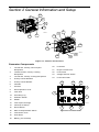
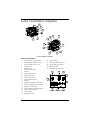
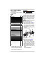
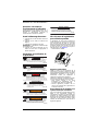
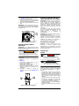
Section 2 General Information and Setup
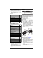
Figure 2-1. Features and Controls
Generator Components
Figure 2-2. Control Panel
000711
000703
15
13
7
19
10
14
21
22
9
8
12
14
6
20
17
24
1 120 Volt AC, 20 Amp, GFCI Duplex
Receptacle
2 120/240 Volt AC, 30 Amp Locking
Receptacle
3 120 Volt AC, 30 Amp Locking Receptacle
4 20 Amp Circuit Breakers
5 30 Amp Circuit Breaker
6Oil Drain
7 Air Filter
8 Decompression Lever
9 Fuel Tank
10 Grounding Lug
11 Start/Run Switch
12 Muffler
13 Fuel Cap/Fuel Gauge
14 Oil Fill (2 locations)
15 Recoil Starter
16 Main 23 Amp Breaker Switch
17 Fuel Return Hose
18 Hour Meter
19 Battery (not included)
20 Fuel Filter
21 Engine On/Off Lever
22 Fuel On/Off
23 Voltage Selector Switch
24 Fuel Primer Bulb
000714
11 18
16
3
1
4 5
2
23

Owner’s Manual for Portable Generator 5
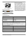
Figure 2-3. Identification Label
Know Your Generator
Replacement owner’s manuals are available
at www.generac.com.
Emissions Information
The U.S. Environmental Protection Agency,
EPA, (and California Air Resource Board,
CARB, for equipment certified to CA stan-
dards) require the generator comply with
exhaust emission standards. The generator is
certified to meet applicable EPA and CARB
emission levels using Ultra Low Sulfur fuel,
Diesel No. 2. Any other use may be a violation
of federal and/or local laws. To ensure the
engine complies with applicable emission
standards for the duration of the engine’s life,
it is important to follow the maintenance speci-
fications in Maintenance Section. Tampering
with or altering the emission control sys-
tem may increase emissions and may be a
violation of Federal or California Law.
000705
(000100a)
WARNING
Consult Manual. Read and understand manual
completely before using product. Failure to
completely understand manual and product
could result in death or serious injury.
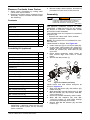
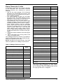
Product Specifications
Generator Specifications
Rated Power Rated 5000 Watts**
Surge Power Surge Rating 5500 Watts
Rated AC Voltage 120/240
Rated AC Load
Current @ 240V
Current @ 120V
20.8 Amps**
41.7 Amps**
Rated Frequency 60 Hz @3600 RPM
Phase Single Phase
** Operating Temperature Range : -18 deg. C (0 deg. F) to 40 Deg. C (104 Deg. F). When
operated above 25 deg. C (77 deg. F) there may be a decrease in power.
** Maximum wattage and current are subject to, and limited by, such factors as fuel Btu con-
tent, ambient temperature, altitude, engine condition, etc.. Maximum power decreases about
3.5% for each 1,000 feet above sea level; and will also decrease about 1% for each 6° C (10°
F) above 16° C (60° F) ambient temperature.
5.5 / 6.5 Engine Specifications
Displacement
435 cc (26.5 in
3
)
Fuel Capacity 45.4 L (12 U.S. gallons)
Oil Type See chart in the Add Engine Oil section.
Oil Capacity 1.6L (1.7 qt)
Run Time at 50% Load 32 Hours
Battery Purchase Locally (not included)
Battery Type 12V 35Ah Battery, Group U1
* Go to Generac.com or contact an Authorized Service Dealer for replacement parts.

6 Owner’s Manual for Portable Generator
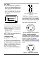
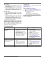
Hour Meter
The Hour Meter tracks hours of operation for
scheduled maintenance. See Figure 2-4.
• The CHG OIL display will illuminate every
100 hours. The message will flash one hour
before and one hour after each 100 hour
interval, providing a two hour window to
perform service.
• The SVC display will illuminate every 100
hours. The message will flash one hour
before and one hour after each 200 hour
interval providing a two hour window to per-
form service.
Figure 2-4. Hour Meter
When the hour meter is in flash alert mode,
the maintenance message will alternate with
elapsed time in hours and tenths. The hours
will flash four times, then alternate with the
maintenance message four times until the
meter automatically resets.
• 100 hours - CHG OIL — Oil Change Inter-
val (Every 100 hrs)
• 200 hours - SVC — Service Air Filter
(Every 200 hrs)
NOTE: The hour glass icon will flash when the
engine is running. This signifies the meter is
recording hours of operation.
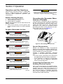
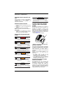
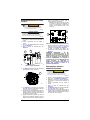
Connection Plugs
120 VAC, 20 Amp, GFCI Duplex
Receptacle
The 120 Volt outlet is overload protected by a
20 Amp push-to-reset circuit breaker. See Fig-
ure 2-5. Each receptacle will power 120 Volt
AC, single phase, 60 Hz electrical loads
requiring up to 2400 watts (2.4 kW) or 20
Amps of current. Use only high quality, well-
insulated, 3-wire grounded cord sets rated for
125 Volts at 20 Amps (or greater).
NOTE: Limit length of extension cords to fif-
teen feet, or less, to prevent voltage drop and
overheating of wires.
Figure 2-5. 120 VAC, 20 Amp, Duplex
Receptacle
120/240 VAC, 30 Amp Receptacle
Use a NEMA L14-30 plug with this receptacle
(rotate to lock/unlock). Connect a suitable 4-
wire grounded cord set to plug and desired
load. The cord set should be rated 250 Volts
AC at 30 Amps (or greater). See Figure 2-6.
Use this receptacle to operate 240 Volt AC, 60
Hz, single phase loads requiring up to 5000
watts (5.0 kW) of power at 20.8 Amps.
Figure 2-6. 120/240 VAC, 30 Amp Receptacle
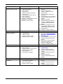
120 VAC, 30 Amp Receptacle
Use a NEMA L5-30 plug with this receptacle
(rotate to lock/unlock). Connect a suitable 3-
wire cord set to the plug and to desired load.
The cord set should be rated for 125 Volts AC
at 30 Amps (or greater). See Figure 2-7.
Use this receptacle to operate 120 Volt AC,
60Hz, single phase loads requiring up to 3600
watts (3.6kW) of power at 30 Amps. The outlet
is protected by a 30 Amp push-to-reset circuit
breaker.
Figure 2-7. 120 VAC, 30 Amp Receptacle
0000.0
000205
000203
000204
000844

Owner’s Manual for Portable Generator 7
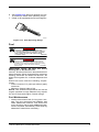
Remove Contents from Carton
1. Open carton completely by cutting each
corner from top to bottom.
2. Remove and verify carton contents prior to
assembly. Carton contents should contain
the following:
Contents
Portability Kit (optional)
3. Call Generac Customer Service 1-888-
GENERAC (1-888-436-3722) with the unit
model and serial number for any missing
carton contents.
4. Record model, serial number, and date of
purchase on front cover of this manual.
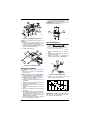
Assembly
Call Generac Customer Service at 1-888-
GENERAC (1-888-436-3722) for any assem-
bly issues or concerns. Please have model
and serial number available.
The following tools are required to install the
accessory kit.
• Ratchet with 10mm and 13mm sockets
• 13mm box wrenches
NOTE: The wheels are not intended for over-
the-road use.
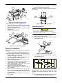
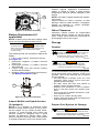
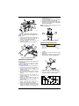
Install wheels as follows. See Figure 2-8.
1. Insert cotter pin (E) to one end of axle (B).
2. In this order; slide washer (D), wheel (A),
washer, (D), axle mount (2-C), washer (D),
wheel (A), washer (D), and cotter pin (E)
onto axle.
3. Place wheel assembly under frame so
axle mounts align with holes in cradle
frame.
4. Secure with M6 screws (L).
.
Figure 2-8. Wheel Assembly
Install frame foot and rubber bumpers as
shown in Figure 2-9.
1. Slide onto M8 screw (Q), flat washer (M),
rubber foot (K).
2. Slide assembly through frame foot (J). Add
M8 flat washer (N), and secure with M8-
1.25 Locknut (P).
3. Place foot bracket assembly under cradle.
4. Slide M8 flat washers (N) onto M8-
1.25x110 screws (T) and insert through
foot bracket assembly and cradle.
5. Secure with M8 flat washer (N) and M8
locknut (P).
Item Qty.
Main Unit 1
Owner’s Manual 1
Liter Oil SAE 30 2
Product Registration Card 3
Service Warranty 1
Emissions Warranty 1
Muffler Extension 1
Battery Bracket Assembly 1
Portability Kit (Model No. G0069100) Qty.
10” Wheel (A) 2
Axle (B) 1
Axle Mount (C) 2
5/8” Flat Washer (D) 4
Cotter Pin (E) 2
Handle (F) 1
Handle Mount (G) 2
Handle Grip (H) 2
Frame Foot (J) 2
Rubber Feet (K) 2
M6-1x50mm Screw (L) 4
.344”x1.0” Flat Washer (M) 2
M8 Flat Washer (N) 10
M8-1.25 Locknut (P) 6
M8-1.25x30 Screw (Q) 2
M8-1.25x45 Screw (R) 2
M8-1.25x50 Screw (S) 2
M8-1.25x110 Screw (T) 2
5/16x1.25 Pin Release (U) 1
Lanyard 1
(000100a)
WARNING
Consult Manual. Read and understand manual
completely before using product. Failure to
completely understand manual and product
could result in death or serious injury.
000704
B
L
E
C
D
C
A

8 Owner’s Manual for Portable Generator
.
Figure 2-9. Frame Foot Assembly
Install handle as shown in Figure 2-10.
1. Place a M8 flat washer (N) onto M8-
1.25x45 screw (R) and through handle
bracket and handle (A).
2. Secure with M8 flat washer (N) and M8
locknut (P).
3. Install handle grips (H).
.
Figure 2-10. Handle Assembly
Battery Installation
The following tools are required to install the
battery.
• 7/16” (11mm) ratchet, socket and wrench
Install the battery as follows. See Figure 2-11.
1. Place battery onto battery tray with the
positive terminal on the right.
2. Connect red battery wire to positive (+) ter-
minal with a bolt, washer and nut.
3. Slide red battery terminal post cover over
terminal and hardware.
4. Connect black battery wire to negative (-)
terminal with a bolt, washer and nut.
5. Slide black battery terminal post cover
over terminal and hardware.
6. Slide one spacer onto each screw.
7. Slide these assemblies through holes in
top of bracket.
8. Place bracket assembly over top of bat-
tery. Do not to touch battery terminal hard-
ware. The screws will pass through holes
on battery tray.
9. Place washer, lock washer and wing nut
onto screw.
10. Tighten wing nuts until the lock washers
are compressed to being flat.
NOTE: The battery charges while the engine
is running.
Figure 2-11. Battery Installation
Add Engine Oil
1. Place generator on a level surface.
2. Verify oil fill area is clean.
3. Remove oil fill cap and wipe dipstick clean.
See Figure 2-12.
Figure 2-12. Remove Dipstick
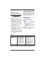
4. Add recommended engine oil as shown in
the following chart.
NOTE: Some units have more than one oil fill
location. It is only necessary to use one oil fill
point.
5. Thread dipstick into oil filler neck. Oil level
is checked with dipstick fully installed.
000710
M
P
P
N
Q
K
T
J
000706
F
R
H
P
N
000716
A
B
(000135)
CAUTION
Engine damage. Verify proper type and quantity of
engine oil prior to starting engine. Failure to do so
could result in engine damage.
000115
-4 °F
(-20 °C)
14 °F
(-10 °C)
32 °F
(0 °C)
50 °F
(10 °C)
68 °F
(20 °C)
86 °F
(30 °C)
104 °F
(40 °C)
SAE 15W-40
SAE 20W
SAE 30
SAE 40
SAE 10-W30
SAE 20W
SAE 10W
000578

Owner’s Manual for Portable Generator 9
6. See Figure 2-13. Remove dipstick and ver-
ify oil level is within safe operating range.
7. Install oil fill cap/dipstick and hand-tighten.
Figure 2-13. Safe Operating Range
Fuel
IMPORTANT NOTE: DO NOT use Home
Heating Oil or Bio-Diesel Fuel.
Use No. 2D diesel fuel when temperatures are
above freezing. When temperatures are below
freezing, blend No.1D diesel fuel and No. 2D
diesel fuel together for a climate adjusted fuel
ratio.
Diesel fuel must meet the following require-
ments:
• Sulfur content of 15 parts per million (ppm)
maximum.
• Minimum Cetane index of 40.
NOTE: Low ambient temperatures as well as
engine operation at high altitudes may require
the use of fuels with higher Cetane ratings.
Fuel Maintenance
• Always treat diesel fuel for long term stor-
age. Use the approved fuel additive and
water abatement material. Test stored fuel
every 90 days and provide additional treat-
ment if required. Periodically check and dry
abatement material as necessary.
000116
(000105)
DANGER
Explosion and Fire. Fuel and vapors are
extremely flammable and explosive. Add fuel
in a well ventilated area. Keep fire and spark
away. Failure to do so will result in death
or serious injury.
(000166b)
DANGER
Explosion and Fire. Do not overfill fuel tank. Fill to
1/2 inch from top of tank to allow for fuel expansion.
Overfilling may cause fuel to spill onto engine causing
fire or explosion, which will result in death or
serious injury.

10 Owner’s Manual for Portable Generator
Section 3 Operation
Operation and Use Questions
Call Generac customer service at 1-888-GEN-
ERAC (1-888-436-3722) with questions or
concerns about equipment operation and
maintenance.
Before Starting Engine
1. Verify engine oil level is correct.
2. Verify fuel level is correct.
3. Verify battery is installed.
NOTE: The generator will not start without the
battery installed.
4. Verify unit is secure on level ground, with
proper clearance and is in a well ventilated
area.
Prepare Generator for Use
Grounding the Generator When
Used as a Portable
The generator is equipped with an equipment
ground connecting the generator frame and
the ground terminals on the AC output recep-
tacles (see NEC 250.34 (A). This allows the
generator to be used as a portable without
grounding the frame of the generator as spec-
ified in NEC 250.34. See Figure 3-1.
• Neutrals bonded to frame.
Figure 3-1.Grounding the Generator
Special Requirements
Review all Federal or State Occupational
Safety and Health Administration (OSHA) reg-
ulations, local codes, or ordinances that apply
to the intended use of the generator.
Consult a qualified electrician, electrical
inspector, or the local agency having jurisdic-
tion:
• In some areas, generators are required to
be registered with local utility companies.
• If the generator is used at a construction
site, there may be additional regulations
which must be observed.
Connecting the Generator to a
Building Electrical System
When connecting directly to a building electri-
cal system, it is recommended that a manual
transfer switch be used. Connections for a
portable generator to a building electrical sys-
tem must be made by a qualified electrician
and in strict compliance with all national and
local electrical codes and laws.
Asphyxiation. Running engines produce
carbon monoxide, a colorless, odorless,
poisonous gas. Carbon monoxide, if not
avoided, will result in death or serious injury.
(000103)
DANGER
(000178a)
Asphyxiation. Always use a battery operated carbon
monoxide alarm indoors and installed according to
the manufacturer’s instructions. Failure to do so
could result in death or serious injury.
WARNING
(000179b)
DANGER
Asphyxiation. The exhaust system must be properly
maintained. Do not alter or modify the exhaust system
as to render it unsafe or make it noncompliant with
local codes and/or standards. Failure to do so will
result in death or serious injury.
WARNING
(000118a)
Risk of fire. Do not use generator without
spark arrestor installed. Failure to do so
could result in death or serious injury.
(000110)
WARNING
Risk of Fire. Hot surfaces could ignite
combustibles, resulting in fire. Fire could
result in death or serious injury.
(000108)
WARNING
Hot Surfaces. When operating machine, do not
touch hot surfaces. Keep machine away from
combustibles during use. Hot surfaces could
result in severe burns or fire.
(000136)
CAUTION
Equipment and property damage. Disconnect electrical
loads prior to starting or stopping unit. Failure to do so
could result in equipment and property damage.
000707

Owner’s Manual for Portable Generator 11
Know Generator Limits
Overloading a generator can result in damage
to the generator and connected electrical
devices. Observe the following to prevent
overload:
• Add up the total wattage of all electrical
devices to be connected at one time. This
total should NOT be greater than the gener-
ator's wattage capacity.
• The rated wattage of lights can be taken
from light bulbs. The rated wattage of tools,
appliances, and motors can be found on a
data label or decal affixed to the device.
• If the appliance, tool, or motor doesn’t give
wattage, multiply volts times ampere rating
to determine watts (volts x amps = watts).
• Some electric motors, such as induction
types, require about three times more watts
of power for starting than for running. This
surge of power lasts only a few seconds
when starting such motors. Make sure to
allow for high starting wattage when select-
ing electrical devices to connect to the gen-
erator:
1. Figure the watts needed to start the largest
motor.
2. Add to that figure the running watts of all
other connected loads.
The Wattage Reference Guide is provided to
assist in determining how many items the gen-
erator can operate at one time.
NOTE: All figures are approximate. See data
label on appliance for wattage requirements.
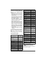
Table 3. Wattage Reference Guide
Transporting/Tipping of the Unit
Do not operate, store or transport the unit at
an angle greater than 15 degrees.
Device Running
Watts
*Air Conditioner (12,000 Btu) 1700
*Air Conditioner (24,000 Btu) 3800
*Air Conditioner (40,000 Btu) 6000
Battery Charger (20 Amp) 500
Belt Sander (3") 1000
Chain Saw 1200
Circular Saw (6-1/2") 800 to 1000
*Clothes Dryer (Electric) 5750
*Clothes Dryer (Gas) 700
*Clothes Washer 1150
Coffee Maker 1750
*Compressor (1 HP) 2000
*Compressor (3/4 HP) 1800
*Compressor (1/2 HP) 1400
Curling Iron 700
*Dehumidifier 650
Disc Sander (9") 1200
Edge Trimmer 500
Electric Blanket 400
Electric Nail Gun 1200
Electric Range (per element) 1500
Electric Skillet 1250
*Freezer 700
*Furnace Fan (3/5 HP) 875
*Garage Door Opener 500 to 750
Hair Dryer 1200
Hand Drill 250 to 1100
Hedge Trimmer 450
Impact Wrench 500
Iron 1200
*Jet Pump 800
Lawn Mower 1200
Light Bulb 100
Microwave Oven 700 to 1000
*Milk Cooler 1100
Oil Burner on Furnace 300
Oil Fired Space Heater (140,000
Btu)
400
Oil Fired Space Heater (85,000 Btu) 225
Oil Fired Space Heater (30,000 Btu) 150
*Paint Sprayer, Airless (1/3 HP) 600
Paint Sprayer, Airless (hand-held) 150
Radio 50 to 200
*Refrigerator 700
Slow Cooker 200
*Submersible Pump (1-1/2 HP) 2800
*Submersible Pump (1 HP) 2000
*Submersible Pump (1/2 HP) 1500
*Sump Pump 800 to 1050
*Table Saw (10") 1750 to 2000
Television 200 to 500
Toaster 1000 to 1650
Weed Trimmer 500
* Allow 3 times the listed watts for starting these
devices.

12 Owner’s Manual for Portable Generator
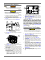
Starting Pull Start Engines
1. Unplug all electrical loads from the unit's
receptacles before starting engine.
2. Place generator on a level surface.
3. Turn main breaker switch Off (A). See Fig-
ure 3-2.
4. Turn fuel valve On (B). See Figure 3-2.
.
Figure 3-2.Main Breaker Switch and
Fuel On/Off Valve
5. See Figure 3-3. Switch engine control lever
to Run (B).
.
Figure 3-3.Engine Control Lever
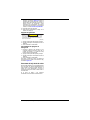
6. See Figure 3-4. Press control panel engine
Run/Stop switch to Run (C).
7. Squeeze primer bulb 5-10 times until firm.
The fuel filter should show fuel level at
least half full.
8. Firmly grasp recoil handle and pull slowly
until increased resistance is felt. Flip red
decompression lever on top of engine. Pull
rapidly up and away.
– Repeat this procedure until the engine
starts. If the engine does not start
within 5 pulls, confirm steps 1-6 and
perform step 7 again.
.
Figure 3-4.Engine Run/Stop Switch
1. Allow engine to run for at least 10 sec-
onds, then turn main breaker On (A). See
Figure 3-2 or Figure 3-4.
2. Select voltage rating with voltage selector
(D). See Figure 3-4.
IMPORTANT NOTE: Do not overload the
generator. Also, do not overload individual
panel receptacles. These outlets are pro-
tected against overload with push-to-reset
type circuit breakers. If amperage rating of
any circuit breaker is exceeded, that
breaker opens and electrical output to that
receptacle is lost. Read Know Generator
Limits carefully.
Starting Electric Start Engines
1. Turn main breaker switch to Off (A). See
Figure 3-2 or Figure 3-4.
2. Unplug all electrical loads from the unit's
receptacles before starting engine.
3. Place generator on a level surface.
4. Turn fuel valve On (A). See Figure 3-2.
5. See Figure 3-3. Switch engine control lever
to Run (B).
6. Squeeze primer bulb 5-10 times until firm.
The fuel filter should show fuel level at
least half full.
7. Press and hold the Engine Start switch (C)
until engine starts. See Figure 3-4.
Release Engine Start switch if engine
does not start within 5 seconds. If engine
does not start within 5 seconds, review
start-up procedure again before attempt-
ing start. If problems persist, refer to Trou-
bleshooting.
8. Turn Main Breaker to On.
9. Select voltage rating with Voltage Selector
(D).
(000183)
WARNING
Recoil Hazard. Recoil could retract unexpectedly.
Kickback could result in death or serious injury.
(000136)
CAUTION
Equipment and property damage. Disconnect electrical
loads prior to starting or stopping unit. Failure to do so
could result in equipment and property damage.
000708
B
A
000712
B
000714
D
C
A
(000136)
CAUTION
Equipment and property damage. Disconnect electrical
loads prior to starting or stopping unit. Failure to do so
could result in equipment and property damage.

Owner’s Manual for Portable Generator 13
Generator Shut Down
1. Turn main breaker switch Off.
2. Switch engine start switch to Off.
3. Turn fuel valve Off.
Emergency Shutdown Procedure
1. Press down on small red lever on lower
engine controls (near recoil handle and
dipstick) to the Stop position.
2. Turn main breaker switch Off.
3. Switch engine start switch to Off.
4. Turn fuel valve Off.
To re-start engine, the engine control lever
must be moved to Run (B). See Figure 3-3.
Low Oil Pressure Switch
The engine is equipped with a low oil pressure
switch that shuts down the engine automati-
cally when the oil level drops below a speci-
fied level. The engine will not run until the oil
has been filled to the proper level.
If the engine shuts down and there is sufficient
fuel, check engine oil level.
(000136)
CAUTION
Equipment and property damage. Disconnect electrical
loads prior to starting or stopping unit. Failure to do so
could result in equipment and property damage.

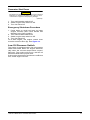
14 Owner’s Manual for Portable Generator
Section 4 Maintenance and Troubleshooting
Maintenance
Regular maintenance will improve perfor-
mance and extend engine/equipment life.
Generac Power Systems, Inc. recommends
that all maintenance work be performed by an
Independent Authorized Service Dealer
(IASD). Regular maintenance, replacement,
or repair of the emissions control devices and
systems may be performed by any repair shop
or person of the owner’s choosing. To obtain
emissions control warranty service free of
charge, the work must be performed by an
IASD. See the emissions warranty.
NOTE: Call 1-888-GENERAC (1-888-436-
3722) with questions about component
replacement.
Maintenance Schedule
Follow maintenance schedule intervals,
whichever occurs first according to use.
NOTE: Adverse conditions will require more
frequent service.
NOTE: All required service and adjustments
should be each season as detailed in the fol-
lowing chart.
Preventive Maintenance
Dirt or debris can cause improper operation
and equipment damage. Clean generator
daily or before each use. Keep area around
and behind muffler free from combustible
debris. Inspect all cooling air openings on
generator.
• Use a damp cloth to wipe exterior surfaces
clean.
• Use a soft bristle brush to loosen caked on
dirt, oil, etc.
• Use a vacuum to pick up loose dirt and
debris.
• Low pressure air (not to exceed 25 psi [172
kPa]) may be used to blow away dirt.
Inspect cooling air slots and openings on
generator. These openings must be kept
clean and unobstructed.
NOTE: DO NOT use a garden hose to clean
generator. Water can enter engine fuel system
and cause problems. If water enters generator
through cooling air slots, some water will be
retained in voids and crevices of rotor and sta-
tor winding insulation. Water and dirt buildup
on generator internal windings will decrease
insulation resistance of windings.
Engine Maintenance
Engine Oil Recommendations
To maintain the product warranty, the engine
oil should be serviced in accordance with the
recommendations of this manual. For your
convenience, maintenance kits designed and
intended for use on this product are available
from the manufacturer that include engine oil,
oil filter, air filter, spark plug(s), a shop towel
and funnel. These kits can be obtained from
an Independent Authorized Service Dealer
(IASD).
At Each Use
Check engine oil level
Every Season
Check valve clearance***
Every 200 Hours or Every Season
Inspect/clean air cleaner filter**
Change oil and oil filter ǂ*
Check engine speed control
Drain fuel tank & replace outlet fuel filter
Every 1000 Hours
Check compression
Every 1500 Hours
Inspect, clean & test fuel injection nozzle
Every 2000 Hours
Check & replace fuel hoses
ǂ Change oil after first 50 hours of opera-
tion, then every season.
* Change oil and oil filter every month
when operating under heavy load or in high
temperatures.
** Clean more often under dirty or dusty
operating conditions. Replace air filter
parts if they cannot be adequately cleaned.
*** Check valve clearance and adjust if
necessary after first 50 hours of operation
and every 400 hours thereafter.
(000142a)
Personal injury. Do not insert any object through the
air cooling slots. Generator can start at any time and
could result in death, serious injury, and unit damage.
WARNING

Owner’s Manual for Portable Generator 15
Inspect Engine Oil Level
Inspect engine oil level prior to each use, or
every 8 hours of operation.
1. Place generator on a level surface.
2. Clean area around oil fill.
3. See Figure 4-1. Remove oil fill cap and
wipe dipstick clean.
Figure 4-1. Engine Oil Fill
4. Screw dipstick into filler neck. Verify oil
level is within safe operating range. See
Figure 4-2.
Figure 4-2. Safe Operating Range
5. Add recommended engine oil as neces-
sary.
6. Replace oil fill cap and hand-tighten.
NOTE: Some units have more than one oil fill
location. It is only necessary to use one oil fill
point.
Change Engine Oil
When using generator under extreme, dirty,
dusty conditions, or in extremely hot weather,
change oil more frequently.
NOTE: Don’t pollute. Conserve resources.
Return used oil to collection centers.
Change oil while engine is still warm from run-
ning, as follows:
1. Place generator on a level surface.
2. Clean area around oil fill, and oil drain
plug.
3. Remove oil fill cap.
4. Remove oil drain plug and drain oil com-
pletely into a suitable container.
5. Install oil drain plug and tighten securely.
6. Slowly pour oil into oil fill opening until oil
level is between the crosshatch marks on
dipstick. DO NOT overfill.
7. Install oil fill cap, and finger tighten.
8. Wipe up any spilled oil.
9. Properly dispose of oil in accordance with
all applicable regulations.
Air Filter
Engine will not run properly and may be dam-
aged if run with a dirty air filter. Service air fil-
ter more frequently in dirty or dusty conditions.
To service air filter:
1. See Figure 4-3. Turn knob (A) and remove
air filter cover.
2. Wash in soapy water. Squeeze filter dry in
clean cloth (DO NOT TWIST).
3. Clean air filter cover before re-installing it.
NOTE: To order a new air filter, contact the
nearest Authorized Service Dealer at 1-888-
GENERAC (1-888-436-3722).
(000135)
CAUTION
Engine damage. Verify proper type and quantity of
engine oil prior to starting engine. Failure to do so
could result in engine damage.
-4 °F
(-20 °C)
14 °F
(-10 °C)
32 °F
(0 °C)
50 °F
(10 °C)
68 °F
(20 °C)
86 °F
(30 °C)
104 °F
(40 °C)
SAE 15W-40
SAE 20W
SAE 30
SAE 40
SAE 10-W30
SAE 20W
SAE 10W
000578
(000139)
WARNING
Risk of burns. Allow engine to cool before
draining oil or coolant. Failure to do so could
result in death or serious injury.
000115
000116
(000130)
WARNING
Accidental Start-up. Disconnect the negative battery
cable, then the positive battery cable when working
on unit. Failure to do so could result in death
or serious injury.

16 Owner’s Manual for Portable Generator
Figure 4-3. Air Filter Assembly
Battery Replacement (if
applicable)
NOTE: A battery may lose some charge when
not in use for prolonged periods of time.
The following tools are required to replace the
battery.
• 7/16” (11mm) ratchet, socket and wrench
See Figure 4-4.
1. Disconnect negative (-) battery terminal
FIRST (A).
2. Disconnect positive (+) battery terminal
SECOND (B).
3. Loosen wing nuts and remove battery
bracket and hardware.
4. Replace battery by following instructions in
the Battery Installation section.
Figure 4-4. Battery Connection
Inspect Muffler and Spark Arrestor
(if equipped)
NOTE: It is a violation of California Public
Resource Code, Section 4442, to use or oper-
ate the engine on any forest-covered, brush-
covered, or grass-covered land unless the
exhaust system is equipped with a spark
arrestor, as defined in Section 4442, main-
tained in effective working order. Other states
or federal jurisdictions may have similar laws.
Contact original equipment manufacturer,
retailer, or dealer to obtain a spark arrestor
designed for exhaust system installed on this
engine.
NOTE: Use ONLY original equipment replace-
ment parts.
Inspect muffler for cracks, corrosion, or other
damage. Remove spark arrestor, if equipped,
inspect for damage or carbon blockage.
Replace parts as required.
Valve Clearance
Important: Please contact an Independent
Authorized Service Dealer for service assis-
tance. Proper valve clearance is essential for
prolonging the life of the engine.
Storage
General
It is recommended to start and run the genera-
tor for 30 minutes, every 30 days. If this is not
possible, refer to the following list to prepare
unit for storage.
• DO NOT place a storage cover on a hot
generator. Allow unit to cool to room tem-
perature before storage.
• DO NOT store fuel from one season to
another unless properly treated.
• Replace fuel container if rust is present.
Rust in fuel will cause fuel system prob-
lems.
• Cover unit with a suitable protective, mois-
ture resistant cover.
• Store unit in a clean and dry area.
• Always store generator and fuel away from
heat and ignition sources.
Prepare Fuel System for Storage
000715
A
(000130)
WARNING
Accidental Start-up. Disconnect the negative battery
cable, then the positive battery cable when working
on unit. Failure to do so could result in death
or serious injury.
000716
B
A
(000143)
DANGER
Explosion and Fire. Fuel and vapors are extremely
flammable and explosive. Store fuel in a well
ventilated area. Keep fire and spark away. Failure
to do so will result in death or serious injury.
(000109)
WARNING
Risk of Fire. Verify machine has properly
cooled before installing cover and storing
machine. Hot surfaces could result in fire.
(000181)
WARNING
Vision Loss. Eye protection is required to avoid
spray from spark plug hole when cranking engine.
Failure to do so could result in vision loss.

Owner’s Manual for Portable Generator 17
Recoil Start
1. Push and hold decompression down and
slowly pull recoil starter 2 to 3 times. Do
not start engine.
2. Pull decompression lever up. Pull recoil
slowly until resistance is felt. This will
close valves so moisture cannot enter
engine cylinder. Gently release recoil.
Electric Start
1. Push and hold decompression lever down.
2. Push Start/Run/Stop switch to turn the
engine for 2 to 3 seconds. Do not start
engine.
3. Pull decompression lever up. Pull recoil
slowly until resistance is felt. This will
close valves so moisture cannot enter
engine cylinder. Gently release recoil.
4. Completely drain fuel tank or completely
fill fuel tank to proper level.
NOTE: Always treat diesel fuel for long term
storage. Use the approved fuel additive and
water abatement material. Test stored fuel
every 90 days and provide additional treat-
ment if required. Periodically check and dry
abatement material as necessary.
Change Oil
Change engine oil before storage. See
Change Engine Oil
Return Engine to Service
1. Refer to the Before Starting Engine sec-
tion.
2. Start engine and run at no load for 5 to 10
minutes while checking:
– oil pressure
– fuel, engine oil or coolant leaks
– proper operation of indicators/gauges
NOTE: Avoid prolonged operation at minimum
or maximum engine speeds and loads for the
first hour of operation.
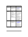
Troubleshooting
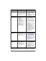
PROBLEM CAUSE CORRECTION
Engine is running, but
AC output is not
available.
1. Circuit breaker OPEN.
2. Poor connection or defective
cord set.
3. Connected device is bad.
4. Fault in generator.
5. Main breaker switch is OFF.
6. Voltage selector switch is OFF.
7. Generator is overloaded.
8. GFCI outlet has tripped.
1. Reset circuit breaker.
2. Check and repair.
3. Connect another device that is
in good condition.
4. Contact Authorized Service
Dealer.
5. Switch main breaker ON.
6. Switch voltage selector switch
to desired voltage output.
7. See
Know Generator Limits
8. Correct ground fault in circuit
and reset GFCI.
Engine runs well at
no-load, but bogs when
load is applied.
1. Short circuit in a connected
load.
2. Generator is overloaded.
3. Engine speed is too slow.
4. Shorted generator circuit.
1. Disconnect shorted electrical
load.
2. See
Know Generator Limits
3. Contact Authorized Service
Dealer.
4. Contact Authorized Service
Dealer.

18 Owner’s Manual for Portable Generator
Engine will not start; or
starts and runs rough.
1. Incorrect start sequence.
2. Fuel valve is OFF.
3. Dirty air filter.
4. Out of fuel.
5. Stale or contaminated fuel.
6. Low oil level.
7. Excessive rich fuel mixture.
8. Dirty fuel filter.
9. Air in fuel system.
10. Engine is under electrical load.
11. Battery not installed.
12. Battery weak or dead.
1. Review & follow starting pro-
cedure.
2. Turn fuel valve ON.
3. Clean or replace air filter.
4. Fill fuel tank.
5. Drain fuel tank and fill with
fresh fuel.
6. Fill crankcase to correct level.
7. Contact Authorized Service
Dealer.
8. Replace fuel filter.
9. Repeat priming procedure. If
no start condition persists
Contact Authorized Service
Dealer.
10. Remove all equipment from
receptacles. Make sure the
main breaker switch is OFF.
11. Install battery.
12. Charge or replace battery.
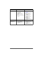
Engine shuts down
during operation.
1. Out of fuel.
2. Low oil level.
3. Fault in engine.
4. Ambient temp too high.
5. Battery weak or dead.
1. Fill fuel tank. Prime fuel sys-
tem. See
Starting Pull Start
Engines or Starting Electric
Start Engines
2. Fill crankcase to correct level.
3. Contact Authorized Service
Dealer.
4. Move unit to cooler location
and allow engine to cool
before running again.
5. Charge or replace battery.
Engine lacks power. 1. Load is too high.
2. Dirty air filter.
3. Engine needs to be serviced.
4. Excessive valve lash.
5. Dirty fuel filter.
6. Fuel injector clogged.
1. Reduce load. See
Know Gen-
erator Limits
2. Clean or replace air filter.
3. Contact Authorized Service
Dealer.
4. Contact Authorized Service
Dealer.
5. Replace fuel filter.
6. Contact Authorized Service
Dealer.
Engine surges or
stumbles.
1. Governor/throttle assembly is
not adjusted properly.
2. Air in fuel system.
3. Battery weak or dead.
1. Contact Authorized Service
Dealer.
2. Contact Authorized Service
Dealer.
3. Charge or replace battery.
PROBLEM CAUSE CORRECTION
Page is loading ...
Page is loading ...
Page is loading ...
Page is loading ...
Page is loading ...
Page is loading ...
Page is loading ...
Page is loading ...
Page is loading ...
Page is loading ...
Page is loading ...
Page is loading ...
Page is loading ...
Page is loading ...
Page is loading ...
Page is loading ...
Page is loading ...
Page is loading ...
Page is loading ...
Page is loading ...
Page is loading ...
Page is loading ...
Page is loading ...
Page is loading ...
Page is loading ...
Page is loading ...
Page is loading ...
Page is loading ...
Page is loading ...
Page is loading ...
Page is loading ...
Page is loading ...
Page is loading ...
Page is loading ...
Page is loading ...
Page is loading ...
Page is loading ...
Page is loading ...
Page is loading ...
Page is loading ...
Page is loading ...
Page is loading ...
Page is loading ...
Page is loading ...
Page is loading ...
Page is loading ...
Page is loading ...
Page is loading ...
Page is loading ...
Page is loading ...
Page is loading ...
Page is loading ...
Page is loading ...
Page is loading ...
Page is loading ...
Page is loading ...
-
 1
1
-
 2
2
-
 3
3
-
 4
4
-
 5
5
-
 6
6
-
 7
7
-
 8
8
-
 9
9
-
 10
10
-
 11
11
-
 12
12
-
 13
13
-
 14
14
-
 15
15
-
 16
16
-
 17
17
-
 18
18
-
 19
19
-
 20
20
-
 21
21
-
 22
22
-
 23
23
-
 24
24
-
 25
25
-
 26
26
-
 27
27
-
 28
28
-
 29
29
-
 30
30
-
 31
31
-
 32
32
-
 33
33
-
 34
34
-
 35
35
-
 36
36
-
 37
37
-
 38
38
-
 39
39
-
 40
40
-
 41
41
-
 42
42
-
 43
43
-
 44
44
-
 45
45
-
 46
46
-
 47
47
-
 48
48
-
 49
49
-
 50
50
-
 51
51
-
 52
52
-
 53
53
-
 54
54
-
 55
55
-
 56
56
-
 57
57
-
 58
58
-
 59
59
-
 60
60
-
 61
61
-
 62
62
-
 63
63
-
 64
64
-
 65
65
-
 66
66
-
 67
67
-
 68
68
-
 69
69
-
 70
70
-
 71
71
-
 72
72
-
 73
73
-
 74
74
-
 75
75
-
 76
76


Generac XD5000E G0068640 User manual
- Category
- Power generators
- Type
- User manual
Ask a question and I''ll find the answer in the document
Finding information in a document is now easier with AI
in other languages
Related papers
-
Generac GP3300 G0064320 User manual
-
Generac GP3300 006432R0 User manual
-
-
-
Generac XD5000E User manual
-
Generac GP17500E User manual
-
Generac GP3300 G0064311 User manual
-
-
Other documents
-
Generac Power Systems GP7500E GP SERIES Owner's manual
-
Uncategorized Colman Powermate User manual
-
DR PRO Series Owner's manual
-
ZUO 50115 Installation guide
-
-
Titan TG 7500D Owner's manual
-
 Sigma Electric 14438 Installation guide
-
Chamberlain 4228 Operating instructions
-
Legrand 2000 Series Plugmold Wired Sections Installation guide
-
JADMAR JSLC-SOL User manual
