Sanyo PLC-ZM5000 Owner's manual
- Category
- Data projectors
- Type
- Owner's manual
This manual is also suitable for

¹
Projection lens is optional.
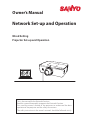
Multimedia Projector
MODEL
PLC-ZM5000
PLC-ZM5000L
¹
Network Supported
Refer to the Owner's Manual below for
details about network function.
Ƒ Network Set-up and Operation
Owner’s Manual

This Multimedia Projector is designed with most advanced technology for portability, durability, and
ease of use. This projector utilizes built-in multimedia features, a palette of 1.07 billion colors, and
matrix liquid crystal display (LCD) technology.
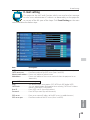
Ƈ Functionally Rich
Ƈ Multi-use Remote Control
Use the remote control as wired and wireless,
or as a PC wireless mouse. Eight remote control
codes and selectable pointer shapes are also
available.
Ƈ Multilanguage Menu Display
Operation menu is available in 12 languages;
English, German, French, Italian, Spanish,
Portuguese, Dutch, Swedish, Russian, Chinese,
Korean, and Japanese. (p.51)
Ƈ Network-capable
- Through an optional PJ-Net Organizer, you can
project an image on a computer as well as
operate and manage the projector via network.
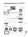
- This projector is loaded with the Wired LAN
network function. You can operate and manage
the projector via network. For details, refer to the
owner’s manual “Network Set-up and Operation.”
This projector has many useful functions such
as lens shifting, ceiling and rear projection,
perpendicular omnidirectional projection, a variety
of lens options, etc.
3Note:
7KH2Q6FUHHQ0HQXDQGILJXUHVLQWKLVPDQXDOPD\GLIIHUVOLJKWO\IURPWKHSURGXFW
7KHFRQWHQWVRIWKLVPDQXDODUHVXEMHFWWRFKDQJHZLWKRXWQRWLFH
Features and Design
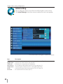
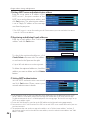
Ƈ Simple Computer System Setting
The projector has the Multi-scan system to conform
to almost all computer output signals quickly (p.36).
Supported resolution up to WUXGA.
Ƈ Direct OFF Function
With the Direct OFF function, you can disconnect
the power cord from the wall outlet or turn off the
breaker even during projection.(p.24)
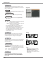
Ƈ Security Function
The Security function helps you to ensure security
of the projector. With the Key lock function, you
can lock the operation on the side control or
remote control (p.61). PIN code lock function
prevents unauthorized use of the projector. (pp.61-
62)
Ƈ Automatic Filter Replacement Function
The projector monitors the condition of the filter
and replaces a filter automatically when it detects
the clogging.
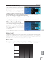
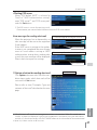
Ƈ Motor-driven Lens Shift
Projection lens can be moved up, down, right and
left with the motor-driven lens shift function. This
function makes it easy to provide projected image
where you want. Zoom and focus can also be
adjusted with a motor-driven operation. (p.17)
Ƈ Power Management
The Power management function reduces power
consumption and maintains lamp life. (p.59)
Ƈ Multiple Interface Terminals
The projector has many interface terminals that
can support various types of equipment and
signals. (p.11)
Ƈ Shutter Function
The projector is equipped with the shutter that
provides complete blackness when the projected
image is not needed with keeping the projector on.
The shutter management function allows you to set
the timer. It prevents from keeping the projector on
when the shutter is closed for a long time. (p.63)
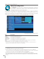
Ƈ
Corner Correction
With the "Horizontal and vertical keystone
correction function" and "Corner keystone
correction function" of this projector, you can
correct the keystone distortion even when
projecting from the diagonal to the screen. (pp.31,
44, 50)
Ƈ Picture in Picture Function
This projector is capable of projecting two images
simultaneously by using either built-in P in P mode
or P by P mode. (pp.55-56)
This projector employs WUXGA LCD panels with 1,920x1,200 pixels, allowing it to project high
resolution signals at their native resolution.
2

Table of Contents
Features and Design ............... 2
Table of Contents .................. 3
To The Owner ..................... 4
Safety Instructions ................. 5
Air Circulation 6
Installing the Projector in Proper Directions 7
Moving the Projector 8
Cautions in Handling the Projector 8
Compliance ....................... 9
Part Names and Functions ......... 10
Front 10
Back 10
Bottom 10
Rear Terminal 11
Side Control and Indicators 12
Remote Control 13
Remote Control Battery Installation 15
Remote Control Receivers and Operating Range 15
Wired Remote Control Transmitter 15
Remote Control Code 16
Adjustable Feet 16
Installation....................... 17
Positioning the Projector 17
Lens Shift Adjustment 17
Lens Installation 18
Connecting to a Computer
(Digital and Analog RGB) 19
Connecting to Video Equipment
(Video, S-video, HDMI) 20
Connecting for Audio Signal 21
Connecting the AC Power Cord 22
Basic Operation .................. 23
Turning On the Projector 23
Turning Off the Projector 24
How to Operate the On-Screen Menu 25
Main Menu 26
Operating with Projector Control 27
Sound Adjustment 28
Operating with Remote Control 29
Keystone Correction 31
Pointer Function 32
Wireless Mouse Operation 32
Input Selection ................... 33
Direct Operation 33
Computer Input Source Selection 34
Video Input Source Selection 35
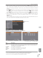
Computer Input................... 36
Computer System Selection 36
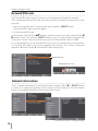
Auto PC Adjustment 37
Manual PC Adjustment 38
Image Level Selection 40
Image Adjustment 41
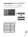
Screen Size Adjustment 42
Video Input ...................... 45
Video System Selection 45
Image Level Selection 46
Image Adjustment 47
Screen Size Adjustment 49
Setting .......................... 51
Setting 51
Maintenance and Care ............. 66
Filter Instructions 66
Replacing the Filter Cartridge 67
Resetting the Filter Counter 68
Resetting the Scroll Counter 68
Lamp Replacement 69
Cleaning the Projection Lens 71
Cleaning the Projector Cabinet 71
Warning Indicators 72
Appendix ........................ 73
Troubleshooting 73
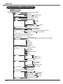
Menu Tree 76
Indicators and Projector Condition 79
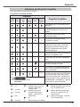
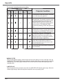
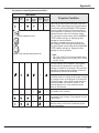
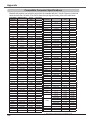
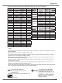
Compatible Computer Specifications 82
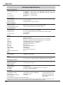
Technical Specifications 84
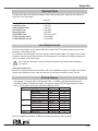
Optional Parts 85
Lens Replacement 85
PJ Link Notice 85
Configurations of Terminals 86
PIN Code Number Memo 87
Dimensions 88
List of Picture in Picture 89
Serial Control Interface 89
Trademarks
Each name of corporations or products in this book is either a registered trademark or a trademark of its respective corporation.
3

Safety Precaution
WARNING: ƔTHIS APPARATUS MUST BE EARTHED.
ƔTO REDUCE THE RISK OF FIRE OR
ELECTRIC SHOCK, DO NOT EXPOSE
THIS APPLIANCE TO RAIN OR
MOISTURE.
– This projector produces intense light from the
projection lens. Do not stare directly into the lens,
otherwise eye damage could result. Be especially
careful that children do not stare directly into the
beam.
– Install the projector in a proper position. Otherwise it
may result in a fire hazard.
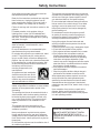
– Allowing the proper amount of space on the top,
sides, and rear of the projector cabinet is critical
for proper air circulation and cooling of the unit.
The diagrams shown here indicate the minimum
space required. If the projector is to be built into a
compartment or similarly enclosed, these minimum
distances must be maintained.
– Do not cover the ventilation slots on the projector.
Heat build-up can shorten the service life of your
projector, and can also be dangerous.
– If the projector is unused for an extended time,
unplug the projector from the power outlet.
– Do not project the same image for a long time. The
afterimage may remain on the LCD panels by the
characteristic of panel.
CAUTION ON HANGING FROM THE CEILING
DO NOT SET THE PROJECTOR IN GREASY, WET,
OR SMOKY CONDITIONS SUCH AS IN A KITCHEN
TO PREVENT A BREAKDOWN OR A DISASTER. IF
THE PROJECTOR COMES IN CONTACT WITH OIL OR
CHEMICALS, IT MAY BECOME DETERIORATED.
To The Owner
CAUTION :TO REDUCE THE RISK OF ELECTRIC
SHOCK, DO NOT REMOVE COVER (OR
BACK). NO USER-SERVICEABLE PARTS
INSIDE EXCEPT LAMP REPLACEMENT.
REFER SERVICING TO QUALIFIED
SERVICE PERSONNEL.
THIS SYMBOL INDICATES THAT DANGEROUS
VOLTAGE CONSTITUTING A RISK OF ELECTRIC
SHOCK IS PRESENT WITHIN THIS UNIT.
THIS SYMBOL INDICATES THAT THERE
ARE IMPORTANT OPERATING AND
MAINTENANCE INSTRUCTIONS IN THE
OWNER'S MANUAL WITH THIS UNIT.
CAUTION
RISK OF ELECTRIC SHOCK
DO NOT OPEN
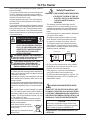
Before installing and operating the projector, read this
manual thoroughly.
The projector provides many convenient features and
functions. Operating the projector properly enables
you to manage those features and maintains it in good
condition for many years to come.
Improper operation may result in not only shortening
the product life, but also malfunctions, fire hazard, or
other accidents.
If your projector seems to operate improperly,
read this
manual again, check operations and cable connections
and try the solutions in the “Troubleshooting” section
in the back of this manual. If the problem still persists,
contact the dealer where you purchased the projector
or the service center.
FOR EU USERS
The symbol mark and recycling systems described be-
low apply to EU countries and do not apply to countries
in other areas of the world.
Your product is designed and manufactured with high
quality materials and components which can be recy-
cled and/or reused.
The symbol mark means that electrical and electronic equip-
ment, batteries and accumulators, at their end-of-life, should
be disposed of separately from your household waste.
Note:
If a chemical symbol is printed beneath the symbol
mark, this chemical symbol means that the battery or
accumulator contains a heavy metal at a certain con-
centration. This will be indicated as follows: Hg: mer-
cury, Cd: cadmium, Pb: lead.
In the European Union there are separate collection
systems for used electrical and electronic equipment,
batteries and accumulators.
Please, dispose of them correctly at
your local community waste collection/
recycling centre.
Please, help us to conserve the environ-
ment we live in!
READ AND KEEP THIS OWNER’S MANUAL FOR
LATER USE.
CAUTION
Not for use in a computer room as defined in the
Standard for the Protection of Electronic Computer/
Data Processing Equipment, ANSI/NFPA 75.
SIDE and TOP REAR
0.7’(20cm)
1.5’(50cm) 3’(1m) 3’(1m)
4

All the safety and operating instructions should be
read before the product is operated.
Read all of the instructions mentioned here and retain
them for later use. Unplug this projector from AC
power supply before cleaning. Do not use liquid or
aerosol cleaners. Use a damp cloth for cleaning.
Follow all warnings and instructions marked on the
projector.
For added protection to the projector during a
lightning storm, or when it is left unattended and
unused for long periods of time, unplug it from the
wall outlet. This will prevent damage due to lightning
and power line surges.
Do not expose this unit to rain or operate it near
water for example, in a wet basement, near a
swimming pool, etc...
Do not use attachments not recommended by the
manufacturer as they may cause hazards.
Do not place this projector on an unstable cart, stand,
or table. The projector may fall, causing serious
injury to a child or adult, and serious damage to the
projector. Use only with a cart or stand recommended
by the manufacturer, or sold with the projector. Wall
or shelf mounting should follow the manufacturer's
instructions, and should use a
mounting kit approved by the
manufacturers.
An appliance and cart combination
should be moved with care. Quick
stops, excessive force, and uneven
surfaces may cause the appliance
and cart combination to overturn.
Slots and openings in the back and side of the
cabinet are provided for ventilation, to ensure reliable
operation of the equipment and to protect it from
overheating.
The openings should never be covered with cloth or
other materials, and the bottom opening should not
be blocked by placing the projector on a bed, sofa,
rug, or other similar surface. This projector should
never be placed near or over a radiator or heat
register.
This projector should not be placed in a built-
in installation such as a book case unless proper
ventilation is provided.
Never push objects of any kind into this projector
through cabinet slots as they may touch dangerous
voltage points or short out parts that could result in a
fire or electric shock. Never spill liquid of any kind on
the projector.
Do not install the projector near the ventilation duct of
air-conditioning equipment.
This projector should be operated only from the type
of power source indicated on the marking label. If you
are not sure of the type of power supplied, consult
your authorized dealer or local power company.
Do not overload wall outlets and extension cords as
this can result in fire or electric shock. Do not allow
anything to rest on the power cord. Do not locate
this projector where the cord may be damaged by
persons walking on it.
Do not attempt to service this projector yourself
as opening or removing covers may expose you
to dangerous voltage or other hazards. Refer all
servicing to qualified service personnel.
Unplug this projector from wall outlet and refer
servicing to qualified service personnel under the
following conditions:
a. When the power cord or plug is damaged or frayed.
b. If liquid has been spilled into the projector.
c. If the projector has been exposed to rain or water.
d. If the projector does not operate normally by
following the operating instructions. Adjust only
those controls that are covered by the operating
instructions as improper adjustment of other
controls may result in damage and will often require
extensive work by a qualified technician to restore
the projector to normal operation.
e. If the projector has been dropped or the cabinet
has been damaged.
f. When the projector exhibits a distinct change in
performance-this indicates a need for service.
When replacement parts are required, be sure the
service technician has used replacement parts
specified by the manufacturer that have the same
characteristics as the original part. Unauthorized
substitutions may result in fire, electric shock, or injury
to persons.
Upon completion of any service or repairs to this
projector, ask the service technician to perform
routine safety checks to determine that the projector
is in safe operating condition.
Safety Instructions
NOTE FOR CUSTOMERS IN THE US
Hg LAMP(S) INSIDE THIS PRODUCT CONTAIN
MERCURY AND MUST BE RECYCLED OR
DISPOSED OF ACCORDING TO LOCAL, STATE OR
FEDERAL LAWS.
5

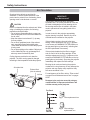
Openings in the cabinet are provided for
ventilation. To ensure reliable operation of the
product and to protect it from overheating, these
openings must not be blocked or covered.
CAUTION
Hot air is exhausted from the exhaust vent. When
using or installing the projector, the following
precautions should be taken.
– Do not put any flammable object or spray can
near the projector, as hot air is exhausted from
the air vents.
– Keep the exhaust vent at least 3' (1 m) away
from any objects.
– Do not touch peripheral parts of the exhaust
vent, especially screws and metallic parts.
These areas will become hot while the projector
is being used.
– Do not put anything on the cabinet. Objects put
on the cabinet will not only get damaged but
also may cause fire hazard by heat.
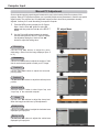
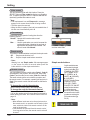
Cooling fans are provided to cool down the
projector. The fans’ running speed is changed
according to the temperature inside the projector.
Exhaust Vent
(Hot air exhaust)
Air Intake Vent
Air flow
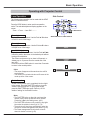
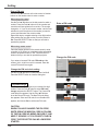
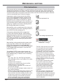
The projector uses a lamp which generates
significant heat. The cooling fans and air vents are
provided to dissipate the heat by drawing air into
the housing and the filter is located in the intake
vents to prevent dust from getting inside of the
projector.
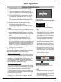
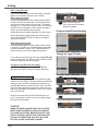
In order to care for the projector appropriately,
regular cleaning is required. Remove any dirt or
dust that has accumulated on the projector.
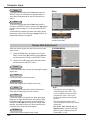
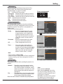
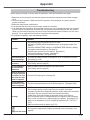
If the projector reaches a time set in the timer
setting, a Filter replacement icon (Fig. 1) appears
on the screen and WARNING FILTER indicator on
the top panel lights up (see below), indicating that
the filter replacement is necessary.
If the projector detects that the filter is clogged
and no scroll is left in the filter cartridge, a Filter
cartridge replacement icon (Fig. 2) appears on the
screen and WARNING FILTER indicator on the top
panel lights up (see below). Stop using the projector
immediately and replace the filter cartridge.
Blocking the air vents and leaving the projector
uncleaned for a long time may not only damage the
projector and may require costly repairs but may
also cause accidents or fire.
For maintenance of the filter, refer to “Filter counter”
on page 65 and “Maintenance and Care” on pages
66-68.
Damages to the projector caused by using an
uncleaned filter or improper maintenance will
void the warranty on the projector.
IMPORTANT!
Filter Maintenance!!
Top Panel
WARNING
FILTER
indicator
Fig. 1 Filter replacement icon
Fig. 2 Filter cartridge
replacement icon
Safety Instructions
Air Circulation
6

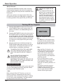
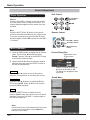
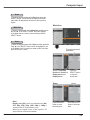
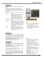
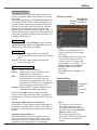
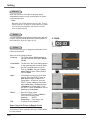
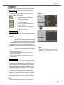
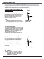
Use the projector properly in specified positions. Improper positioning may shorten the lamp life and result
in severe accidents or fire hazard.
This projector can project the picture in upward, downward, or inclined position in perpendicular direction
to the horizontal plane. When installing the projector in downwardly inclined position, install the projector
bottom side up.
Avoid positioning the projector as described below when installing.
Positioning Precautions
Do not tilt the projector more
than 10 degrees from side to
side.
Do not put the projector on
either side to project an image.
Û
Û
10° 10°
10°
10°
In upward projection, do
not tilt the projector over 10
degrees right and left.
In downward projection, do
not tilt the projector over 10
degrees right and left.
For ceiling mounting, you need the ceiling mount kit designed for this projector. When not
mounted properly, the projector may fall, causing hazards or injury. For details, consult your
dealer. The warranty on this projector does not cover any damage caused by use of any non-
recommended ceiling mount kit or installation of the ceiling mount kit in an improper location.
CAUTION ON CEILING MOUNTING
Safety Instructions
3Note:
7RLQYHUVHRUUHYHUVHWKHLPDJHVHWWKHFHLOLQJIXQFWLRQWROnSS
Installing the Projector in Proper Directions
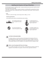
Do not radiate strong light such as laser light on the projection lens directly, as this may
degrade the functionality of the projector, and will void any applicable warranties.
Cautious use of equipment with laser technology
7

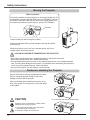
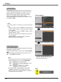
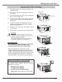
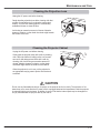
Use the handle grip when moving the projector.
Retract the adjustable feet to prevent damage to the lens and cabinet
when carrying.
When this projector is not in use for an extended period, put it into a
suitable case to protect the projector.
CAUTION IN CARRYING OR TRANSPORTING THE PROJECTOR
– Do not drop or bump the projector, otherwise damages or malfunctions may result.
– When carrying the projector, use a suitable carrying case.
– Do not transport the projector by courier or any other transport service in an unsuitable transport
case. This may cause damage to the projector. For information about transporting the projector by
courier or any other transport service, consult your dealer.
– Do not put the projector in a case before it is cooled enough.
Do not hold the lens or the lens compartment tube when
lifting or moving the projector. Doing so may cause
damage to the lens and the projector.
Care must be taken when handling the projector; do not
drop, bump, subject it to strong forces, or put other things
on the cabinet.
Do not
hold the lens and the peripheral part.
CAUTION
Projection lens is a motorized lens. Please note the
followings when using the projector.
Ɣ 'RQRWWRXFKWKHOHQVZKLOHLWLVPRYLQJDVWKLV
could cause injury to the fingers.
Ɣ 1HYHUDOORZFKLOGUHQWRWRXFKWKHOHQV
Safety Instructions
Moving the Projector
Cautions in Handling the Projector
Protector
Notes on protector
Remove the protector on the lens before use, and keep it for later use. For
transportation, press and hold the LENS button or LENS SHIFT button for
more than 5 seconds to make the lens return to the central position, and
then attach the protector to protect the lens. (Only for PLC-ZM5000)
8

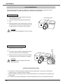
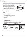
AC Power Cord for the United Kingdom:
This cord is already fitted with a moulded plug incorporating a fuse, the value of which is indicated on
the pin face of the plug. Should the fuse need to be replaced, an ASTA approved BS 1362 fuse must
be used of the same rating, marked thus
ASA
. If the fuse cover is detachable, never use the plug with the
cover omitted. If a replacement fuse cover is required, ensure it is of the same colour as that visible
on the pin face of the plug (i.e. red or orange). Fuse covers are available from the Parts Department
indicated in your User Instructions.
If the plug supplied is not suitable for your socket outlet, it should be cut off and destroyed.
The end of the flexible cord should be suitably prepared and the correct plug fitted.
WARNING: A PLUG WITH BARED FLEXIBLE CORD IS HAZARDOUS IF ENGAGED IN A LIVE
SOCKET OUTLET.
The Wires in this mains lead are coloured in accordance with the following code:
Green-and-yellow ············· Earth
Blue ······························ Neutral
Brown ···························· Live
As the colours of the wires in the mains lead of this apparatus may not correspond with the coloured
markings identifying the terminals in your plug proceed as follows:
The wire which is coloured green-and-yellow must be connected to the terminal in the plug which is
marked by the letter E or by the safety earth symbol
or coloured green or green-and-yellow.
The wire which is coloured blue must be connected to the terminal which is marked with the letter N or
coloured black.
The wire which is coloured brown must be connected to the terminal which is marked with the letter L
or coloured red.
WARNING: THIS APPARATUS MUST BE EARTHED.
The AC Power Cord supplied with this projector meets the requirement for use in the country you purchased
it.
AC Power Cord for the United States and Canada:
AC Power Cord used in the United States and Canada is listed by the Underwriters
Laboratories (UL) and certified by the Canadian Standard Association (CSA).
AC Power Cord has a grounding-type AC line plug. This is a safety feature to be
sure that the plug will fit into the power outlet. Do not try to defeat this safety feature.
Should you be unable to insert the plug into the outlet, contact your electrician.
GROUND
THE SOCKET-OUTLET SHOULD BE INSTALLED NEAR THE EQUIPMENT AND EASILY ACCESSIBLE.
AC Power Cord Requirement
Federal Communications Commission Notice
Note: This equipment has been tested and found to comply with the limits for a Class B digital device,
pursuant to Part 15 of the FCC Rules. These limits are designed to provide reasonable protection against
harmful interference in a residential installation. This equipment generates, uses and can radiate radio
frequency energy and, if not installed and used in accordance with the instructions, may cause harmful
interference to radio communications. However, there is no guarantee that interference will not occur in a
particular installation. If this equipment does cause harmful interference to radio or television reception,
which can be determined by turning the equipment off and on, the user is encouraged to try to correct
the interference by one or more of the following measures:
– Reorient or relocate the receiving antenna.
– Increase the separation between the equipment and receiver.
–
Connect the equipment into an outlet on a circuit different from that to which the receiver is
connected.
– Consult the dealer or an experienced radio/TV technician for help.
Use of shielded cable is required to comply with class B limits in Subpart B of Part 15 of FCC Rules.
Do not make any changes or modifications to the equipment unless otherwise specified in the
instructions. If such changes or modifications should be made, you could be required to stop operation of
the equipment.
Model Number : PLC-ZM5000, PLC-ZM5000L
Trade Name : Sanyo
Responsible party : SANYO NORTH AMERICA CORPORATION
Address : 21605 Plummer Street, Chatsworth, California 91311, U.S.A.
Telephone No. : (818)998-7322
Compliance
9

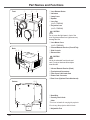
Part Names and Functions
CAUTION
Hot air is exhausted from the exhaust
vent. Do not put heat-sensitive objects
near this side.
Lens Release Button
Indicators
Lamp Cover
Speaker
Lens Cap
(for PLC-ZM5000)
Projection Lens
(for PLC-ZM5000)
Do not cover the light beam in front of the
lens. High temperature from light beam may
damage the lens.
Lens Mount Cover
(for PLC-ZM5000L)
Infrared Remote Receiver (Front & Top)
Side Controls
Exhaust Vent
Front
Bottom
Back
Infrared Remote Receiver (Back)
Terminals and Connectors
Filter Cover & Air Intake Vent
Power Cord Connector
Rear Cover (Optional Parts Attachment)
Hand Grip
Security Chain Hook
3Note:
7KLVLVQRWDKDQGOHIRUFDUU\LQJWKHSURMHFWRU
'RQRWFDUU\WKHSURMHFWRUZLWKWKLVKRRN
Adjustable Feet
CAUTION
10

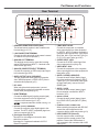
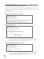
DIGITAL (DVI-D) TERMINAL
Connect the computer output digital signal to this
terminal. The HDTV (HDCP compatible) signal can
also be connected (pp.19-20).
USB CONNECTOR (Series B)
Use this connector when controlling a
computer with the remote control of the
projector. Connect the USB terminal of
your computer to this connector with a USB
cable (p.19).
VIDEO INPUT JACK
Connect the component or the composite
video output signal from video equipment to
these jacks (p.20).
CONTROL PORT CONNECTOR
When controlling the projector with RS-232C,
connect the control equipment to this
connector with the serial control cable (p.19).
HDMI TERMINAL
Connect the HDMI signal (including sound signal)
from video equipment or the DVI signal from
computer to this terminal (pp.19, 20).
is registered trademarks of HDMI Licensing, LLC.
ANALOG (COMPUTER INPUT TERMINAL)
Connect the computer (or RGB scart) output signal
to this terminal (pp.19-20).
5 BNC INPUT JACKS
Connect the component or composite
video output signal from video equipment
to VIDEO/Y, and Pr/Cr.jacks or connect the
computer output signal(5 BNC Type [Green,
Blue, Red, Horiz. Sync, and Vert. Sync.]) to
G, B, R, H/V, and V jacks (pp.19-20).
Part Names and Functions
S-VIDEO INPUT JACK
Connect the S-VIDEO output signal from
video equipment to this jack (p.20).
¸
¸ Kensington Security Slot
This slot is for a Kensington lock used to deter
theft of the projector.
*Kensington is a registered trademark of ACCO
Brands Corporation.
INFRARED REMOTE RECEIVER (Back)
The infrared remote receiver is also located in the
front and top (pp.10, 15).
ANALOG OUT TERMINAL
This terminal can be used to output the incoming
analog RGB signal from INPUT 1-3 terminal to the
other monitor (pp.19-20).
LAN CONNECTION TERMINAL
Connect the LAN cable (refer to the owner’s manual
of “Network Set-up and Operation”).
Rear Terminal
R/C JACK
When using the wired remote control, connect
the wired remote control to this jack with a remote
control cable (not supplied) (p.15).
AUDIO OUTPUT JACK (VARIABLE)
This jack outputs the audio signal from computer,
video, HDMI equipment or 5 BNC INPUT jacks to
external audio equipment (p.21).
AUDIO 2 JACK
Connect the audio output (stereo) signal
from 5 BNC INPUT jacks (INPUT 2 jacks).
(p.21)
AUDIO 1 JACK
Connect the audio output (stereo) signal
from a computer connected to INPUT 1
terminals. (p.21)
AUDIO 3 JACKS (L(MONO)/R)
Connect the audio output (stereo) signal
from video equipment connected to INPUT
3 jacks (p.21). For a monaural audio signal
(a single audio jack), connect it to the L
(MONO) jack.
11

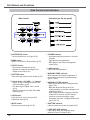
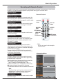
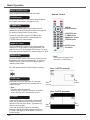
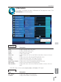
ON/STAND-BY button
Turn the projector on or off (pp.23-24).
MENU button
Open or close the On-Screen Menu (p.25).
Point ŸźŻŹ ( VOLUME – / + buttons
– Select an item or adjust the value in the
On-Screen Menu (p.25).
– Pan the image in Digital zoom + mode
(p.43).
±$GMXVWWKHYROXPHOHYHOZLWK3RLQWŻŹ
buttons) (p.28).
WARNING TEMP. indicator
Blink red when the internal temperature of
the projector exceeds the operating range
(pp.72, 79-80).
SHUTTER button
Close and open up the built-in shutter (p.27).
POWER indicator
– Light green while the projector is in stand-
by mode.
– Light green during operations.
– Blink green in the Power management
mode (p.59).
SELECT button
– Execute the selected item (p.25).
– Expand or compress the image in the
Digital zoom mode (p.43).
LAMP indicator
Light red during operations.
LAMP REPLACE indicator
Light orange when the projection lamp
reaches its end of life (pp.69, 80).
WARNING FILTER indicator
– Blink slow when the filter is being scrolled
(pp.66, 79).
– Blink fast when the filter scroll is not
working properly or the filter cartridge is not
installed (pp.66, 81).
– Light orange when the clogging of the filter
is detected or the filter counter reaches
a time set in the timer setting, urging
immediate filter/ filter cartridge replacement
(pp.65, 66, 81).
Side Control
Indicators (on the top panel)
Part Names and Functions
INPUT button
Select an input source (pp.33-35).
LENS button
Enter the focus, zoom, and lens shift
adjustment mode (p.27).
SHUTTER
indicator
Light blue when the shutter is closed (p.79).
Side Control and Indicators
12

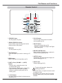
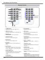
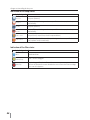
STAND-BY button
Turn the projector off (p.24).
ON button
Turn the projector on (p.23).
INPUT button
Select a signal (pp.33-35).
L-CLICK button
Act as the left mouse button for wireless mouse
operation (p.32).
SIGNAL EMISSION indicator
Light red while a signal is being sent from the
remote control to the projector.
POINT ŸźŻŹ( VOLUME – / +, MUTE)
buttons
– Select an item or adjust the value in the
On-Screen Menu (p.25).
– Pan the image in Digital zoom + mode (p.43).
±$GMXVWWKHYROXPHOHYHOZLWK3RLQWŻŹ
EXWWRQVRUPXWHWKHVRXQGZLWK3RLQWź
button) (p.28).
To ensure safe operation, observe the
following precautions:
– Do not bend, drop, or expose the remote control
to moisture or heat.
– For cleaning, use a soft dry cloth. Do not apply
benzene, thinner, spray, or any other chemical
materials.
SELECT button
– Execute the selected item (p.25).
– Expand or compress the image in the Digital
zoom mode (p.43).
MENU button
Open or close the On-Screen Menu (p.25).
MOUSE POINTER button
Move a pointer of the projector or a pointer for
wireless mouse operation (p.32).
Part Names and Functions
AUTO PC button
Automatically adjust the computer image to its
optimum setting (pp.29, 37).
SHUTTER button
Close and open up the built-in shutter (pp.27,
29).
Remote Control
R-CLICK button
Act as the right mouse button for wireless
mouse operation (p.32).
13

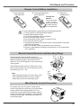
ZOOM buttons
Zoom in and out the images (p.29).
D.ZOOM button
Select the Digital zoom +/- mode and resize the
image (p.43).
PIP button
Operate the Picture in Picture function (pp.30,
55-56).
FILTER button
Scroll the filter (p.30).
FREEZE button
Freeze the picture on the screen (p.30).
KEYSTONE button
Correct keystone distortion (pp.31, 44, 50).
ON/OFF switch
When using the remote control, set this switch
to “ON”. Set it to “OFF” for power saving when
it is not in use (p.16).
LENS SHIFT button
Select the Lens Shift function (p.29).
P-TIMER button
Operate the P-timer function (pp.30, 60).
NUMBER buttons
Act as number buttons. Use these buttons when
setting the remote control codes (p.16) or when
entering the PIN code numbers (pp. 23, 54, 62).
POINTER button
Act as the On-Off switch for the Pointer (pp.30,
32, 60).
Part Names and Functions
INPUT 1- 3 buttons
Select an input source (INPUT 1 – INPUT 3)
(pp.33-35).
Remote Control
FOCUS buttons
Adjust the focus (p.29).
SCREEN button
Select the screen size (p.29).
INFO. button
Display the input source information (p.29).
IMAGE SEL. button
Operate the image selection function (pp.40, 46).
IMAGE ADJ. button
Operate the image adjustment function (pp.41-
42, 47-48).
For PIN code
and remote
control code.
WIRED REMOTE jack
Connect the remote control cable (not supplied)
to this jack when using as a wired remote
control.
14

12 3
Open the battery
compartment lid.
Install new batteries into
the compartment.
Replace the
compartment lid.
Two AAA size
batteries
For correct polarity
(+ and –), be sure
battery terminals are
in contact with pins
in the compartment.
To ensure safe operation, please observe the following precautions :
Ɣ 8VHWZR$$$RU/5W\SHDONDOLQHEDWWHULHV
Ɣ $OZD\VUHSODFHEDWWHULHVLQVHWV
Ɣ 'RQRWXVHDQHZEDWWHU\ZLWKDXVHGEDWWHU\
Ɣ $YRLGFRQWDFWZLWKZDWHURUOLTXLG
Ɣ 'RQRWH[SRVHWKHUHPRWHFRQWUROWRPRLVWXUHRUKHDW
Ɣ 'RQRWGURSWKHUHPRWHFRQWURO
Ɣ ,IWKHEDWWHU\KDVOHDNHGRQWKHUHPRWHFRQWUROFDUHIXOO\ZLSHWKHFDVHFOHDQ
and install new batteries.
Ɣ 5LVNRIDQH[SORVLRQLIEDWWHU\LVUHSODFHGE\DQLQFRUUHFWW\SH
Ɣ'LVSRVHRIXVHGEDWWHULHVDFFRUGLQJWRWKHLQVWUXFWLRQVRU\RXUORFDOGLVSRVDO
rule or guidelines.
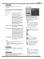
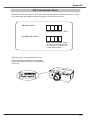
Point the remote control toward the projector (to
Infrared Remote Receivers) when pressing the buttons.
Maximum operating range for the remote control is
about 16.4’ (5 m) and 60 degrees in front, back and top
of the projector.
Infrared Remote Receivers are provided in front, back
and top of the projector. You can conveniently use all of
the receivers (pp. 10, 11, 59).
16.4’
(5 m)
The remote control can be used as a wired remote
control. Wired remote control helps you use the remote
control outside of the operating range (16.4’/ 5 m).
Connect the remote control and the projector with the
remote control cable (sold separately). Connected with
the remote control cable, the remote control does not
emit wireless signal.
Part Names and Functions
16.4’
(5 m)
3Note:
:KHQKDQJLQJWKHSURMHFWRUIURPWKHFHLOLQJVHOHFW
WKH,QIUDUHG5HPRWH5HFHLYHUZKLFKLVORFDWHG
IDUWKHUDZD\IURPWKHIOXRUHVFHQWOLJKWS
Remote Control Battery Installation
Wired Remote Control Transmitter
Remote Control Receivers and Operating Range
15

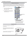
The eight different remote control codes (Code 1–Code 8) are assigned to this projector. Switching the
remote control codes prevents interference from other remote controls when several projectors or video
equipment next to each other are being operated at the same time. Change the remote control code for
the projector first before changing that for the remote control. See “Remote control” in the Setting Menu on
page 58.
Press and hold the MENU and a number
button (1–8) for more than five seconds to
switch among the codes.
Press and hold the MENU and a number
button (1-8) that corresponds to the
remote control code for more than five
seconds to switch among the codes.
Part Names and Functions
Remote Control Code
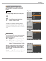
Adjustable
Feet
Projection angle can be adjusted up to 4.0 degrees with
the adjustable feet.
Rotate the adjustable feet and tilt the projector to the
proper height; to raise the projector, rotate the feet of
both clockwise.
To lower the projector or to retract the adjustable feet,
rotate the feet of both counterclockwise.
Adjustable Feet
MENU button
Number buttons
(1-8)
ON/OFF
Switch
1
2
To reset the remote control code, press and
hold the MENU and the number button 0 for
more than five seconds.
16

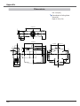
Installation
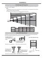
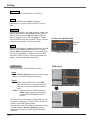
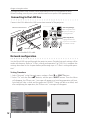
For projector positioning, see the figures below. The projector should be set perpendicularly to the plane of
the screen. (for PLC-ZM5000)
3Note:
7KHEULJKWQHVVLQWKHURRPKDVDJUHDWLQIOXHQFHRQSLFWXUHTXDOLW\,WLVUHFRPPHQGHGWROLPLWDPELHQW
OLJKWLQJLQRUGHUWRREWDLQWKHEHVWLPDJH
$OOPHDVXUHPHQWVDUHDSSUR[LPDWHDQGPD\YDU\IURPWKHDFWXDOVL]HV
100
''
46.1
'
(14.0 m)
34.6
'
(10.5 m)
23.0
'
(7.0 m)
11.4
'
(3.5 m)
200
''
300
''
400
''
236
''
177
''
118
''
59
''
40
''
Max. Zoom
Min. Zoom
Screen Size
(W x H) mm
16:10 aspect ratio
Zoom (min.)
40''
Zoom (max.)
862 x 538
4.5'(1.4 m)
7.7'(2.4 m)
100''
2154 x 1346
11.4' (3.5 m)
19.5' (5.9 m)
200''
4308 x 2692
23.0' (7.0 m)
39.2' (12.0 m)
300''
6462 x 4039
34.6'(10.5 m)
58.9' (18.0 m)
400''
8616 x 5385
46.1'(14.0 m)
78.6' (24.0 m)
(Inch Diagonal)
(Center)
78.6
'
(24.0 m)
400''
4.5'(1.4 m)
Positioning the Projector
60%
10%
Lens shift center
position
Shift range
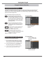
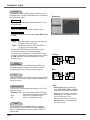
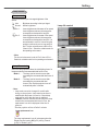
Lens Shift Adjustment
Projection lens can be moved from side to side and up and down with the motor-driven lens shift function.
This function makes the positioning of images easy on the screen. (See page 27)
The display position can
be shifted upward up
to 60% elevation of the
display.
The display position can be
shifted downward up to 60%
low level of the display.
The display position
can be shifted to
the left in up to 10%
width of the display.
The display position can
be shifted to the right in
up to 10% width of the
display.
When the lens is shifted to top. When the lens is shifted to bottom.
When the lens is shifted to leftmost.
When the lens is shifted to rightmost.
Lens shift adjustable range
17

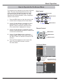
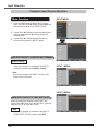
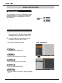
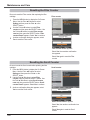
When replacing the lens or using an optional lens, install the lens by following the instructions below.
Ask the sales dealer for detailed information of the optional lens specifications.
Shift the lens to the central position by using the
Lens shift function (p.27).
1
2
Removing the lens
Lens release button
CAUTION
Be careful when handling the lens. Do not drop.
3
Installation
While pressing the Lens release button on the top
of the cabinet, turn the lens counterclockwise until
it stops and pull it out slowly from the projector.
Turn off the projector and unplug the AC power
cord.
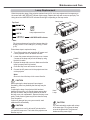
NOTES ON LENS INSTALLATION
Ɣ'RQRWWRXFKRUUHPRYHDQ\SDUWVH[FHSWWKHOHQVDQGUHODWHGSDUWV,WPD\UHVXOWLQPDOIXQFWLRQV
electrical shock, fire hazard or other accidents.
Ɣ%HIRUHLQVWDOOLQJRUUHSODFLQJWKHOHQVFKHFNWKDWWKH0RGHO1RRIWKH3URMHFWLRQ/HQVPDWFKHVZLWK
the projector.
Ɣ )RUGHWDLOVRIWKHOHQVDQGLQVWDOODWLRQFRQWDFWWKHVDOHVGHDOHUZKHUH\RXSXUFKDVHGWKHSURMHFWRU
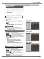
Fit the lens to the projector by aligning the red dot
on the lens with the red dot of the projector.
Slowly turn the lens clockwise until it clicks. Make
sure that the lens is fully inserted to the projector.
Remove the lens mount cover
CAUTION
Do not press the lens release button when
attaching the lens.
Lens Installation
Attaching the lens to the projector
Red
dots
1
2
3
18

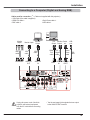
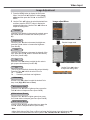
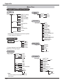
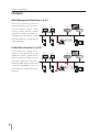
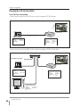
8QSOXJWKHSRZHUFRUGVRIERWKWKH
SURMHFWRUDQGH[WHUQDOHTXLSPHQW
IURPWKH$&RXWOHWEHIRUHFRQQHFWLQJ
FDEOHV
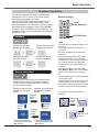
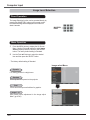
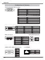
Cables used for connection (
¼
= Cables not supplied with this projector.)
9*$&DEOH2QHFDEOHLVVXSSOLHG
+'0,'9,FDEOH¼
%1&FDEOH¼
6HULDO&URVVFDEOH¼
86%FDEOH¼
Installation
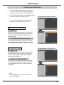
See the next page for the signals that can output
to the ANALOG OUT terminal.
γ
Connecting to a Computer (Digital and Analog RGB)
Monitor
Output
BNC
cable
DVI
Output
G B R H/V V
HDMI-
DVI
cable
VGA
cable
VGA
cable
USB
cable
USB
port
Monitor
Output
HDMI
ANALOG
IN
ANALOG
OUT
Serial
Cross
cable
CONTROL
PORT
Serial
out
γ
Monitor Input
USB
DIGITAL
IN
DVI-
Digital
cable
Monitor
Output
19

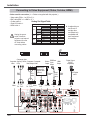
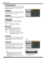
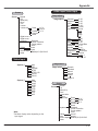
8QSOXJWKHSRZHU
FRUGVRIERWKWKH
SURMHFWRUDQGH[WHUQDO
HTXLSPHQWIURPWKH
$&RXWOHWEHIRUH
FRQQHFWLQJFDEOHV
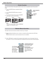
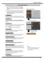
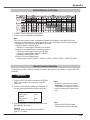
Cables used for connection (¼ = Cables not supplied with this projector.)
9LGHRFDEOH5&$[RU5&$[
¼
%1&FDEOH%1&[RU%1&[
¼
6YLGHRFDEOH
¼
6FDUW9*$FDEOH
¼
+'0,FDEOH
¼
Installation
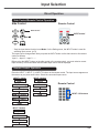
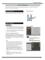
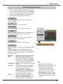
Analog Out Signal Table
¿
A cable with one
end D-sub 15
and the other
end (Black box)
compatible with
each equipment
is necessary.
Connecting to Video Equipment (Video, S-video, HDMI)
RGB Scart
21-pin
Output
S-video
cable
S-video
Output
Composite
Video
Y - Pb/
Cb - Pr/Cr
BNC
cable
Component
Video Output
Composite
Video
Component Video
Output (Y, Pb/Cb,
Pr/Cr)
HDMI
Output
HDMI
cable
Scart-
VGA
cable
Video
HDMI
ANALOG
IN
ANALOG
OUT
S-VIDEO
Refer to the
Analog Out
Signal Table
(above).
Video
Y - Pb/
Cb - Pr/Cr
DVI-Digital
cable
DIGITAL
IN
RCA
cable
Digital Output
(HDCP
compatible)
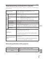
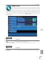
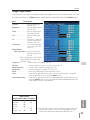
Input Terminal Monitor Out Cable
Input 1
D-sub15
RGB (PC analog) YES
RGB (SCART) NO
DVI
RGB (PC digital) NO
RGB (AV HDCP) NO
HDMI
HDMI NO
Input 2 5 BNC
RGB YES
Video YES
¿
Y, Pb/Cb, Pr/Cr YES
¿
Input 3
RCA
Y, Pb/Cb, Pr/Cr YES
¿
S-video
S-video NO
Video
Video YES
¿
Network
NO
20
Page is loading ...
Page is loading ...
Page is loading ...
Page is loading ...
Page is loading ...
Page is loading ...
Page is loading ...
Page is loading ...
Page is loading ...
Page is loading ...
Page is loading ...
Page is loading ...
Page is loading ...
Page is loading ...
Page is loading ...
Page is loading ...
Page is loading ...
Page is loading ...
Page is loading ...
Page is loading ...
Page is loading ...
Page is loading ...
Page is loading ...
Page is loading ...
Page is loading ...
Page is loading ...
Page is loading ...
Page is loading ...
Page is loading ...
Page is loading ...
Page is loading ...
Page is loading ...
Page is loading ...
Page is loading ...
Page is loading ...
Page is loading ...
Page is loading ...
Page is loading ...
Page is loading ...
Page is loading ...
Page is loading ...
Page is loading ...
Page is loading ...
Page is loading ...
Page is loading ...
Page is loading ...
Page is loading ...
Page is loading ...
Page is loading ...
Page is loading ...
Page is loading ...
Page is loading ...
Page is loading ...
Page is loading ...
Page is loading ...
Page is loading ...
Page is loading ...
Page is loading ...
Page is loading ...
Page is loading ...
Page is loading ...
Page is loading ...
Page is loading ...
Page is loading ...
Page is loading ...
Page is loading ...
Page is loading ...
Page is loading ...
Page is loading ...
Page is loading ...
Page is loading ...
Page is loading ...
Page is loading ...
Page is loading ...
Page is loading ...
Page is loading ...
Page is loading ...
Page is loading ...
Page is loading ...
Page is loading ...
Page is loading ...
Page is loading ...
Page is loading ...
Page is loading ...
Page is loading ...
Page is loading ...
Page is loading ...
Page is loading ...
Page is loading ...
Page is loading ...
Page is loading ...
Page is loading ...
Page is loading ...
Page is loading ...
Page is loading ...
Page is loading ...
Page is loading ...
Page is loading ...
Page is loading ...
Page is loading ...
Page is loading ...
Page is loading ...
Page is loading ...
Page is loading ...
Page is loading ...
Page is loading ...
Page is loading ...
Page is loading ...
Page is loading ...
Page is loading ...
Page is loading ...
Page is loading ...
Page is loading ...
Page is loading ...
Page is loading ...
Page is loading ...
Page is loading ...
Page is loading ...
Page is loading ...
Page is loading ...
Page is loading ...
Page is loading ...
Page is loading ...
Page is loading ...
Page is loading ...
Page is loading ...
Page is loading ...
Page is loading ...
Page is loading ...
Page is loading ...
Page is loading ...
Page is loading ...
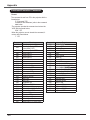
-
 1
1
-
 2
2
-
 3
3
-
 4
4
-
 5
5
-
 6
6
-
 7
7
-
 8
8
-
 9
9
-
 10
10
-
 11
11
-
 12
12
-
 13
13
-
 14
14
-
 15
15
-
 16
16
-
 17
17
-
 18
18
-
 19
19
-
 20
20
-
 21
21
-
 22
22
-
 23
23
-
 24
24
-
 25
25
-
 26
26
-
 27
27
-
 28
28
-
 29
29
-
 30
30
-
 31
31
-
 32
32
-
 33
33
-
 34
34
-
 35
35
-
 36
36
-
 37
37
-
 38
38
-
 39
39
-
 40
40
-
 41
41
-
 42
42
-
 43
43
-
 44
44
-
 45
45
-
 46
46
-
 47
47
-
 48
48
-
 49
49
-
 50
50
-
 51
51
-
 52
52
-
 53
53
-
 54
54
-
 55
55
-
 56
56
-
 57
57
-
 58
58
-
 59
59
-
 60
60
-
 61
61
-
 62
62
-
 63
63
-
 64
64
-
 65
65
-
 66
66
-
 67
67
-
 68
68
-
 69
69
-
 70
70
-
 71
71
-
 72
72
-
 73
73
-
 74
74
-
 75
75
-
 76
76
-
 77
77
-
 78
78
-
 79
79
-
 80
80
-
 81
81
-
 82
82
-
 83
83
-
 84
84
-
 85
85
-
 86
86
-
 87
87
-
 88
88
-
 89
89
-
 90
90
-
 91
91
-
 92
92
-
 93
93
-
 94
94
-
 95
95
-
 96
96
-
 97
97
-
 98
98
-
 99
99
-
 100
100
-
 101
101
-
 102
102
-
 103
103
-
 104
104
-
 105
105
-
 106
106
-
 107
107
-
 108
108
-
 109
109
-
 110
110
-
 111
111
-
 112
112
-
 113
113
-
 114
114
-
 115
115
-
 116
116
-
 117
117
-
 118
118
-
 119
119
-
 120
120
-
 121
121
-
 122
122
-
 123
123
-
 124
124
-
 125
125
-
 126
126
-
 127
127
-
 128
128
-
 129
129
-
 130
130
-
 131
131
-
 132
132
-
 133
133
-
 134
134
-
 135
135
-
 136
136
-
 137
137
-
 138
138
-
 139
139
-
 140
140
-
 141
141
-
 142
142
-
 143
143
-
 144
144
-
 145
145
-
 146
146
-
 147
147
-
 148
148
-
 149
149
-
 150
150
-
 151
151
-
 152
152


Sanyo PLC-ZM5000 Owner's manual
- Category
- Data projectors
- Type
- Owner's manual
- This manual is also suitable for
Ask a question and I''ll find the answer in the document
Finding information in a document is now easier with AI
Related papers
-
Sanyo PLC WTC500AL User manual
-
Sanyo PLC-HP7000L Owner's manual
-
Sanyo Sanyo PLC-ZM5000S User manual
-
Sanyo PLC-EF60A Owner's manual
-
-
Sanyo WTC500L User manual
-
Sanyo PLC-XTC50L Owner's manual
-
Sanyo PLC-XTC50AL User manual
-
-
Sanyo Sanyo PLC-XW200 User manual
Other documents
-
Eiki LC-WGC500A User manual
-
-
-
-
Eiki LC-WXL200A User manual
-
-
-
-
-
Hitachi CP-X608 User's Manual And Operating Manual