Harman Kardon AVR 145 Owner's manual
- Category
- AV receivers
- Type
- Owner's manual

ENGLISH
AVR 145 Audio/ Video Receiver
OWNER’S MANUAL
30935_AVR145_ENG 01/12/06 9:53 Side 1

2 TABLE OF CONTENTS
3 Introduction
4 Safety Information
4 Unpacking
5 Front Panel Controls
7 Rear Panel Connections
9 Main Remote Control Functions
12 Installation and Connections
12 Audio Connections
12 Video Connections
14 SCART A/V Connections
15 Power Connections
16 Speaker Selection
16 Speaker Placement
17 System Configuration
17 First Turn On
17 Using the On-Screen Display
17 System Setup
18 Input Setup
19 Surround Setup
20 Night Mode Settings
20 Configuring the Surround Off
(Stereo) Modes
21 Automated Speaker Setup Using EzSet
22 Manual Setup
22 Speaker Setup
24 Delay Settings
26 Output Level Adjustment
28 Operation
28 Surround Mode Chart
30 Basic Operation
30 Source Selection
30 6-Channel Direct Input
31 Controls and Use of Headphones
31 Surround Mode Selection
31 Digital Audio Playback
32 Dolby Digital
32 DTS
32 PCM Audio Playback
32 Selecting a Digital Source
32 Digital Bitstream Indicators
32 Surround mode Types
33 Surround Mode Post Processing
34 PCM Playback Indications
34 Speaker/Channel Indicators
35 Night Mode
35 Tape Recording
35 Using The Bridge
36 Output Level Adjustment
With Source Signals
36 Dim function
36 Memory backup
37 System Setup
37 Front Panel Display Fade
37 Turn-On Volume Level
37 Semi-OSD Settings
38 Full-OSD Time Out Adjustment
38 Default Surround Mode
38 Full-OSD Background Color
39 Tuner Operation
39 Basic Tuner Operation
39 Station Selection
39 Preset Tuning
40 RDS Operation
40 RDS Tuning
40 RDS Display Options
40 Program Search
41 Programming the Remote
41 Programming the Remote with Codes
Table of Contents
Typographical Conventions
In order to help you use this manual with the remote control, front-panel controls and rear-panel con-
nections, certain conventions have been used.
EXAMPLE – (bold type) indicates a specific remote control or front-panel button, or rear-panel
connection jack
EXAMPLE – (OCR type) indicates a message that is visible on the front-panel information display
1
– (number in a square) indicates a specific front-panel control
0
– (number in a circle) indicates a rear-panel connection
0
– (number in an oval) indicates a button or indicator on the remote
å
– (letter in an oval) indicates a button on the Zone II remote
The appearance of the text or cursor for your receiver’s on-screen menus may vary slightly from the illus-
trations in this manual. Whether the text appears in all uppercase or upper- and lowercase characters,
performance and operation remain the same.
Declaration of Conformity
We, Harman Consumer Group, Inc.
2, route de Tours
72500 Château-du-Loir,
FRANCE
declare in own responsibility, that the product
described in this owner’s manual is in compliance
with technical standards:
EN 55013:2001 + A1:2003
EN 55020:2002 + A1:2003
EN 61000-3-2:2000
EN 61000-3-3:1995 + A1:2001
EN 60065:2002
Jurjen Amsterdam
Harman Consumer Group, Inc.
11/06
41 Direct Code Entry
41 Auto Search Method
41 Code Readout
42 Macro Programming
42 Programmed Device Functions
42 Volume Punch-Through
43 Channel Control Punch-Through
43 Transport Control Punch-Through
43 Resetting the Remote Memory
44 Function List
46 Troubleshooting Guide
46 Processor Reset
47 Technical Specifications
48 Appendix - Settings Worksheet
30935_AVR145_ENG 01/12/06 9:53 Side 2

INTRODUCTION 3
ENGLISH
Introduction
Thank you for choosing Harman Kardon!
With the purchase of a Harman Kardon AVR 145
you are about to begin many years of listening
enjoyment. Designed to provide all the excitement
and detail of movie soundtracks and every nuance
of musical selections, the AVR is truly a multichan-
nel receiver for the new millennium. In addition to
the traditional 5.1 digital decoding modes such as
Dolby Digital and DTS, it offers the latest advance-
ments in surround technology such as Dolby Pro
Logic II, the full suite of DTS modes, DTS Neo:6
and the latest 5.1 channel versions of Harman's
own Logic 7 technology.
The AVR has been engineered so that it is easy
to take advantage of all the power of its digital
technology. On-screen menus, fully color coded
connection jacks and terminals make installation
fast and simple. However, to obtain the maxi-
mum enjoyment from your new receiver, we urge
you to read this manual. A few minutes spent
learning the functions of the various controls will
enable you to take advantage of all the power
the AVR is able to deliver.
If you have any questions about this product, its
installation or its operation, please contact your
retailer or custom installer. They are your best
local sources of information.
Description and Features
The AVR is among the most versatile and multi-
featured A/V receivers available, incorporating a
wide range of listening options. In addition to
Dolby Digital and DTS decoding for digital
sources, a broad choice of surround modes for
Matrix surround-encoded or Stereo recordings are
available for use with sources such as CD, VCR, TV
broadcasts and the AVR’s own FM/AM tuner.
Along with Dolby Digital, Dolby Pro Logic II, DTS
Neo:6, DTS 96/24, Dolby 3 Stereo, 5 Channel
Stereo and Hall and Theater modes, the AVR offers
Harman International’s exclusive Logic 7 process
in 5.1 versions to create a wider, more enveloping
field environment and more defined fly-overs and
pans.
Dolby Virtual Speaker is available to create
enveloping sound fields from front left and right
speakers, and the latest Dolby Headphone
circuitry creates an amazing sense of openness
with headphones.
In addition to providing a wide range of listening
options, the AVR is easy to configure so that it
provides the best results with your speakers and
specific listening-room environment.
A Stereo-Direct mode bypasses the digital proces-
sor to preserve all of the subtleties of older analog,
two-channel materials, while bass management,
available in the surround and Stereo-Digital
modes,improves your ability to tailor the sound to
suit your room acoustics or taste.
The AVR 145 takes the “video” part of its name
seriously. Along with two 100MHz analog com-
ponent video inputs, the AVR 145 provides A/V
sync delay so that the lip sync errors – commonly
seen when digital video processing is used in a
source, program or video display – are
eliminated.
For the ultimate in flexibility, the AVR features
connections for four video devices, all with both
composite and S-Video inputs. Two additional
audio inputs are available, and a total of six digi-
tal inputs and two outputs make the AVR 145
capable of handling all the latest digital audio
sources.
Coax and optical digital outputs are available for
direct connection to digital recorders. A video
recording output and a color-coded eight-channel
input make the AVR 145 virtually future-proof,
with everything needed to accommodate to-
morrow’s new formats right on board.
Until now, Harman Kardon AVRs have been able
to accommodate almost any source device
equipped with line-level analog, optical digital or
coaxial digital outputs, including most digital
media players. With one simple connection
between the AVR 145 and the optional
Harman Kardon , you are able to listen
to materials stored on your compatible Apple
®
iPod
®
**. Your AVR’s system remote control has
been preprogrammed with control codes that
enable you to select tracks for playback and
navigate many of your iPod’s functions, even from
across the room. The Bridge
™
will even let you
charge your iPod.
The AVR 145’s powerful amplifier uses traditional
Harman Kardon high-current design technologies
to meet the wide dynamic range of any program
selection.
Harman Kardon invented the high-fidelity
receiver more then fifty years ago. With state-of-
the-art circuitry and time-honored circuit designs,
the AVR 145 is the perfect combination of the
latest in digital audio technology, a quiet yet
powerful analog amplifier in an elegant,
easy-to-use package.
■ Dolby* Digital, Dolby Digital and Dolby
Pro Logic* II Decoding, and the full suite
of DTS
®
modes, including DTS Neo:6
®
■ Five channels of high-current
amplification
■ Harman Kardon’s exclusive Logic 7
®
processing, for 5.1 processing in a
variety of modes
■ remote automatically sets
out-
put levels for optimum performance
■ Stereo-Direct Mode for Two-Channel
Sources Bypasses DSP Processing to
Preserve the Integrity of Analog
Materials
■ Stereo-Digital Mode for Programmable
Bass Management of Low Frequencies
Between Main Speakers and Subwoofer
■ Front panel analog A/V inputs
■ Front panel digital inputs for easy con-
nection to portable digital devices and
the latest video game consoles
■ Connects to Harman Kardon’s
(optional) for charging, playback and
control of a compatible Apple
®
iPod
®
device
■ Input titling for all input sources (except
tuner)
■ Multiple digital inputs and outputs
■ On-screen menu and display system
with choice of blue or black background
screen
■ A/V Sync delay adjustable for each input
delivers perfect lip sync with digital pro-
grams or video displays
■ 6-Channel Direct Input for Use with
Future Audio Formats
■ Extensive bass management options,
including three separate crossover
groupings
■ Main Remote with Internal Codes
TM
**Compatible with all iPod models equipped with a dock connector, including third-generation “Click Wheel” models and newer. Not compatible with iPod
shuffle models. Although iPod photo models are compatible, images stored on the iPod may not be viewed.
30935_AVR145_ENG 01/12/06 9:53 Side 3

4 SAFETY INFORMATION
Safety Information
Important Safety Information
READ THIS BEFORE OPERATING
YOUR UNIT.
Do not install this equipment in a confined space
such as a case or similar – away from direct
sunlight, heat sources, vibration, dust, moisture,
and/or cold. Avoid installing this unit where for-
eign object may fall onto this unit and/or this
unit may be exposed to liquid dripping or
splashing. On the top of this unit, do not place:
– Burning objects (i.e. candles), as they may
cause fire, damage to this unit, and/or personal
injury.
– Containers with liquid in them, as they may fall
and liquid may cause electrical shock to the
user and/or damage to this unit.
Do not cover this unit with a newspaper, table-
cloth, curtain, etc. in order not to obstruct heat
radiation. If the temperature inside this unit rises,
it may cause fire, damage to this unit, and/or per-
sonal injury.
Install this unit near the AC outlet and where the
AC power plug can be reached easily.
This unit is not disconnected from the AC power
source as long as it is connected to the wall out-
let, even if this unit itself is turned off. This state
is called the standby mode. In this state, this unit
is designed to consume a very small quantity of
power.
WARNING
TO REDUCE THE RISK OF FIRE OR ELECTRIC
SHOCK, DO NOT EXPOSE THIS APPLIANCE
TO RAIN OR MOISTURE.
Verify Line Voltage Before Use
Your AVR has been designed for use with
220-240-Volt AC current. Connection to a line
voltage other than that for which it is intended
can create a safety and fire hazard and may
damage the unit.
If you have any questions about the voltage
requirements for your specific model, or about
the line voltage in your area, contact your dealer
before plugging the unit into a wall outlet.
Do Not Use Extension Cords
To avoid safety hazards, use only the power cord
attached to your unit. We do not recommend that
extension cords be used with this product. As
with all electrical devices, do not run power cords
under rugs or carpets or place heavy objects on
them. Damaged power cords should be replaced
immediately by an authorized service depot with
a cord meeting factory specifications.
Handle the AC Power Cord Gently
When disconnecting the power cord from an AC
outlet, always pull the plug, never pull the cord.
If you do not intend to use the unit for any
considerable length of time, disconnect the plug
from the AC outlet.
Do Not Open the Cabinet
There are no user-serviceable components inside
this product. Opening the cabinet may present a
shock hazard, and any modification to the prod-
uct will void your guarantee. If water or any
metal object such as a paper clip, wire or a staple
accidentally falls inside the unit, disconnect it
from the AC power source immediately, and
consult an authorized service station.
Installation Location
■ To assure proper operation and to avoid the
potential for safety hazards, place the unit on
a firm and level surface. When placing the unit
on a shelf, be certain that the shelf and any
mounting hardware can support the weight of
the product.
■ Make certain that proper space is provided
both above and below the unit for ventilation.
If this product will be installed in a cabinet or
other enclosed area, make certain that there is
sufficient air movement within the cabinet.
Under some circumstances a fan may be
required.
■ Do not place the unit directly on a carpeted
surface.
■ Avoid installation in extremely hot or cold
locations, or an area that is exposed to direct
sunlight or heating equipment.
■ Avoid moist or humid locations.
■ Do not obstruct the ventilation slots on the
top of the unit, or place objects directly over
them.
■ Due to the weight of the AVR 145 and the heat
generated by the amplifiers, there is the remote
possibility that the rubber padding on the
bottom of the unit’s feet may leave marks on
certain wood or veneer materials. Use caution
when placing the unit on soft woods or other
materials that may be damaged by heat or
heavy objects. Some surface finishes may be
particularly sensitive to absorbing such marks
due to a variety of factors beyond
Harman Kardon's control, including the nature
of the finish, cleaning materials used, and
normal heat and vibration caused by the use of
the product, or other factors. We recommend
that caution be exercised in choosing an instal-
lation location for the component and in nor-
mal maintenance practices, as your warranty
will not cover this type of damage to furniture.
Cleaning
When the unit gets dirty, wipe it with a clean,
soft, dry cloth. If necessary, wipe it with a soft
cloth dampened with mild soapy water, then a
fresh cloth with clean water. Wipe dry im-
mediately with a dry cloth. NEVER use benzene,
aerosol cleaners, thinner, alcohol or any other
volatile cleaning agent. Do not use abrasive
cleaners, as they may damage the finish of metal
parts. Avoid spraying insecticide near the unit.
Moving the Unit
Before moving the unit, be certain to disconnect
any interconnection cords with other compo-
nents, and make certain that you disconnect the
unit from the AC outlet.
Unpacking
The carton and shipping materials used to pro-
tect your new receiver during shipment were
specially designed to cushion it from shock and
vibration. We suggest that you save the carton
and packing materials for use in shipping if you
move, or should the unit ever need repair.
To minimize the size of the carton in storage, you
may wish to flatten it. This is done by carefully
slitting the tape seams on the bottom and
collapsing the carton. Other cardboard inserts
may be stored in the same manner. Packing
materials that cannot be collapsed should be
saved along with the carton in a plastic bag.
If you do not wish to save the packaging
materials, please note that the carton and other
sections of the shipping protection are recyclable.
Please respect the environment and discard
those materials at a local recycling center.
It is important that you remove the protective
plastic film from the front-panel lens. Leaving the
film in place will affect the performance of your
remote control.
30935_AVR145_ENG 01/12/06 9:53 Side 4

FRONT PANEL CONTROLS 5
ENGLISH
1
Main Power Switch: Press this button to
apply power to the AVR. When the switch is
pressed in, the unit is placed in a Standby
mode, as indicated by the orange LED
3
. This
button MUST be pressed in to operate the unit.
To turn the unit off completely and prevent the
use of the remote control, this switch should be
pressed until it pops out from the front panel so
that the word “OFF” may be read at the top of
the switch.
NOTE: This switch is normally left in the “ON”
position.
2
System Power Control: When the Main
Power Switch
1
is “ON,” press this button to
turn on the AVR; press it again to turn the unit
off (to Standby). Note that the Power Indicator
3
will turn blue when the unit is on.
3
Power Indicator: This LED will be illuminated
in orange when the unit is in the Standby mode
to signal that the unit is ready to be turned on.
When the unit is in operation, the indicator will
turn blue.
4
Headphone Jack: This jack may be used to
listen to the AVR’s output through a pair of head-
phones. Be certain that the headphones have a
standard 6.3 mm stereo phone plug. Note that
the speakers will automatically be turned off
when the headphones are connected.
5
Surround Mode Group Selector: Press
this button to select the top-level group of
surround modes. Each press of the button will
select a major mode grouping in the following
order:
Dolby Modes ➜ DTS Digital Modes ➜ DSP
Modes ➜ Stereo Modes ➜ Logic 7 Modes
Once the button is pressed so that the name of
the desired surround mode group appears in the
Main Information Display
Ò
, press the
Surround Mode Selector
9
to cycle through
the individual modes available. For example, press
this button to select Dolby modes, and then press
the Surround Mode Selector
9
to choose
from the various mode options.
6
Speaker Select Button: Press this button
to begin the process of selecting the speaker
positions that are used in your listening room.
(See page 16 for more information on setup and
configuration.)
Front Panel Controls
1
2
3
4
5
6
7
8
9
)
!
@
#
$
%
^
&
*
(
Ó
Ô
Ò
Ú
Û
Ù
ı
Main Power Switch
System Power Control
Power Indicator
Headphone Jack
Surround Mode Group Selector
Speaker Select Button
Selector Buttons
Tone Mode
Surround Mode Selector
Tuning
Tuner Band Selector
Set Button
Preset Stations Selector
Speaker/Channel Input Indicator
Input Source Selector
RDS Select Button
Delay
Digital Optical 3 Input
Surround Mode Indicators
Digital Coax 3 Input
Video 3 input jacks
Input Indicators
Main Information Display
Remote Sensor Window
Digital Input Selector
Channel Select Button
Volume Control
DIGITAL LOGIC 7
VID 1
DVD
CD
FMAM
TAPE
6 8 CH
VID 2
VID 3
PRO LOGIC
3 STEREO
HEADPHONE
DSP
5 7 CH. STEREO
SURR. OFF
30935_AVR145_ENG 01/12/06 9:53 Side 5

6 FRONT PANEL CONTROLS
Front Panel Controls
7
Selector Buttons: When you are establishing
the AVR’s configuration settings, use these buttons
to select from the choices available, as shown in
the Main Information Display
Ò
.
8
Tone Mode: Pressing this button enables or
disables the Balance, Bass and Treble tone
controls. When the button is pressed so that the
words
TONE IN appear in the Main
Information Display
Ò
, the settings of the
Bass and Treble controls and of the Balance
control will affect the output signals. When the
button is pressed so that the words
TONE
OUT
appear in the Main Information
Display
Ò
, the output signal will be “flat,”
without any balance, bass or treble alteration.
9
Surround Mode Selector: Press this button
to select from among the available surround
mode options for the mode group selected. The
specific modes will vary based on the number of
speakers available, the mode group and if the
input source is digital or analog. For example,
press the Surround Mode Group Selector
5
to select a mode grouping such as Dolby or
Logic 7, and then press this button to see the
mode choices available. For more information on
mode selection, see page 28.
)
Tuning Selector: Press the left side of the
button to tune lower frequency stations and the
right side of the button to tune higher frequency
stations. When a station with a strong signal is
reached,
MANUAL TUNED or AUTO
TUNED
will appear in the Main Information
Display
Ò
(see page 40 for more information
on tuning stations).
!
Tuner Band Selector: Pressing this button
will automatically switch the AVR to the Tuner
mode. Pressing it again will switch between the
AM and FM frequency bands, holding it pressed
for some seconds will switch between stereo and
mono receiving and between automatic and
manual tuning mode (See page 40 for more
information on the tuner).
@ Set Button: When making choices during the
setup and configuration process, press this button
to enter the desired setting as shown in the
Main Information Display
Ò
into the AVR’s
memory.
#
Preset Stations Selector: Press this
button to scroll up or down through the list of
stations that have been entered into the preset
memory (See page 40 for more information on
tuner programming).
$
Speaker/Channel Input Indicators: These
indicators are multipurpose, indicating either the
speaker type selected for each channel or the
incoming data-signal configuration.The left, center,
right, right surround and left surround speaker
indicators are composed of three boxes, while the
subwoofer is a single box. The center box lights
when a “Small” speaker is selected, and the two
outer boxes light when “Large” speakers are
selected. When none of the boxes are lit for the
center, surround or subwoofer channels, no speaker
has been selected for that position. (See page 22
for more information on configuring speakers.) The
letters inside each of the center boxes display
active input channels. For standard analog inputs,
only the L and R will light, indicating a stereo
input. When a digital source is playing, the indica-
tors will light to display the channels begin
received at the digital input. When the letters
flash, the digital input has been interrupted.
(See page 34 for more information on the Channel
Indicators).
%
Input Source Selector: Press this button to
change the input by scrolling through the list of
input sources.
^
RDS Select Button: Press this button to
display the various messages that are part of the
RDS data system of the AVR’s tuner.
(See page 40 for more information on RDS).
&
Delay: Press this button to begin the
sequence of steps required to enter delay time
settings (See page 24 for more information on
delay times).
*
Digital Optical 3 Input: Connect the optical
digital audio output of an audio or video product
to this jack. When the Input is not in use, be
certain to keep the plastic cap installed to avoid
dust contamination that might degrade future
performance.
(
Surround Mode Indicators: The current
selected mode or function will appear as one of
these indicators. Note that when the unit is
turned on, the entire list of available modes will
light briefly, and then revert to normal operation
with only the active mode indicator illuminated.
Ó
Digital Coax 3 Input: This jack is normally
used for connection to the output of portable
digital audio devices, video game consoles or
other products that have a coax digital jack.
Ô
Video 3 Input Jacks: These audio/video
jacks may be used for temporary connection to
video games or portable audio/video products
such as camcorders and portable audio players.
Input indicators: The current selected
mode or function will appear as one of these
indicators. Note that when the unit is turned on,
the entire list of available modes will light briefly,
and then revert to normal operation with only
the active mode indicator illuminated.
Ò
Main Information Display: This display
delivers messages and status indications to help
you operate the receiver.
Ú
Remote Sensor Window: The sensor
behind this window receives infrared signals from
the remote control. Aim the remote at this area
and do not block or cover it unless an external
remote sensor is installed.
Note: When /DMP has been selected as
the input source, no Input Indicator
will
light.
DMP/THE BRIDGE IS
CONNECTED
will scroll across the Upper
Display Line
Ò
, unless you have retitled the
source name, in which case that name will
appear. See page 18 for more information on
input titling.
Û
Digital Input Selector: When playing a
source that has a digital output, press this button
to select between the Optical
L
and Coaxial
9
Digital inputs. (See pages 18 and 31 for
more information on digital audio).
Ù
Channel Select Button: Press this button
to begin the process of trimming the channel
output levels using an external audio source.
(For more information on output level trim
adjustment, see page 36).
ı
Volume Control: Turn this knob clockwise
to increase the volume, counterclockwise to
decrease the volume. If the AVR is muted,
adjusting volume control will automatically
release the unit from the silenced condition.
30935_AVR145_ENG 01/12/06 9:53 Side 6

REAR PANEL CONNECTIONS 7
ENGLISH
Rear Panel Connections
0
1
2
3
4
5
6
7
8
9
A
B
C
D
E
F
G
H
I
J
K
L
M
N
O
P
Q
R
S
T
U
AM Antenna
FM Antenna
Tape Inputs
Tape Outputs
Subwoofer Output
DVD Audio Inputs
CD Inputs
Video 1 Audio Outputs
DMP Connector
6-Channel Direct Inputs
Digital Audio Outputs
Video Monitor Outputs
DVD Video Inputs
Front Speaker Outputs
Center Speaker Outputs
Surround Speaker Outputs
Switched AC Accessory Outlet
Video 1 Audio Inputs
AC Power Cord
Video 2 Component Video Inputs
Component Video Outputs
Video 1 Component Video Inputs
Video 2 Audio Inputs
Coaxial Digital Inputs
Video 2 Video Inputs
Video 1 Video Outputs
Video 1 Video Inputs
Optical Digital Inputs
RS-232 Serial Port
RS-232 Mode
RS-232 Reset
NOTE: To assist in making the correct connec-
tions for multichannel input/output and speaker
connections, all connection jacks and terminals
have been color coded in conformance with the
latest CEA standards as follows:
Front Left: White
Front Right: Red
Center: Green
Surround Left: Blue
Surround Right: Gray
Surround Back Left: Brown
Surround Back Right: Tan
Subwoofer (LFE): Purple
Digital Audio: Orange
Composite Video: Yellow
Component Video “Y”: Green
Component Video “Pr”: Red
Component Video “Pb”: Blue
0
AM Antenna: Connect the AM loop antenna
supplied with the receiver to these terminals. If an
external AM antenna is used, make connections to
the AM and GND terminals in accordance with
the instructions supplied with the antenna.
1
FM Antenna: Connect the supplied indoor or
an optional external FM antenna to this terminal.
2
Tape Inputs: Connect these jacks to the
PLAY/OUT jacks of an audio recorder.
3
Tape Outputs: Connect these jacks to the
RECORD/INPUT jacks of an audio recorder.
4
Subwoofer Output: Connect this jack to
the line-level input of a powered subwoofer. If an
external subwoofer amplifier is used, connect this
jack to the subwoofer amplifier input.
5
DVD Audio Inputs: Connect these jacks to
the analog audio jacks on a DVD or other audio
or video source.
6
CD Inputs: Connect these jacks to the
analog output of a compact disc player or CD
changer or any other audio source.
7
Video 1 Audio Outputs: Connect these
jacks to the RECORD/INPUT audio jacks on
a VCR or any other Audio recorder.
8
Digital Media Player (DMP)
Connector: With the AVR 145 turned off, con-
nect one end of the optional Harman Kardon
to this proprietary connector, and the
other to your compatible Apple iPod.When the
Digital Media Player source is selected, you may
view your iPod’s control and navigation
messages on your video display (if one is con-
nected to one of the Video Monitor Outputs
B
), and in the Upper and Lower Display
Lines
Ò
. You may navigate the iPod and select
tracks for playback using the
⁄
/
¤
/
‹
/
›
Buttons
DE
, the Set Button
F
and
Transport Controls
P
on your AVR remote.
See page 35 for more information.
30935_AVR145_ENG 01/12/06 9:53 Side 7

8 REAR PANEL CONNECTIONS
Rear Panel Connections
9
6-Channel Direct Inputs: These jacks are
used for connection to source devices such as
DVD-Audio or SACD players with discrete analog
outputs.
A
Digital Audio Outputs: Connect these
jacks to the matching digital input connector on
a digital recorder such as a CD-R or MiniDisc
recorder.
B
Video Monitor Outputs: Connect this jack
to the composite and/or S-Video input of a TV
monitor or video projector to view the on-screen
menus and the output of any standard Video or
S-Video source selected by the receiver’s video
switcher.
C
DVD Video Inputs: Connect these jacks to
the composite or S-Video output jacks on a DVD
player or other video source.
D
Front Speaker Outputs: Connect these
outputs to the matching + or – terminals on
your left and right speakers. In conformance with
the new CEA color code specification, the White
terminal is the positive, or "+" terminal that
should be connected to the red (+) terminal on
Front Left speaker with the older color coding,
while the Red terminal is the positive, or "+"
terminal that should be connected to the red (+)
terminal on Front Right speaker. Connect the
black (–) terminals on the AVR to the black (–)
terminals on the speakers. See page 12 for more
information on speaker polarity.
E
Center Speaker Outputs: Connect these
outputs to the matching + and – terminals on
your center channel speaker. In conformance
with the new CEA color code specification, the
Green Terminal is the positive, or "+" terminal
that should be connected to the red (+) terminal
on speakers with the older color coding. Connect
the black (–) terminal on the AVR to the black
negative (–) terminal on your speaker. (See page
12 for more information on speaker polarity.)
F
Surround Speaker Outputs: Connect
these outputs to the matching + and – terminals
on your surround channel speakers. In confor-
mance with the new CEA color code specifica-
tion, the Blue terminal is the positive, or "+"
terminal that should be connected to the red (+)
terminal on the Surround Left speaker with older
color coding, while the Gray terminal should be
connected to the red (+) terminal on the
Surround Right speaker with the older color
coding. Connect the black (–) terminal on the
AVR to the matching black negative (–)
terminals for each surround speaker. (See page
12 for more information on speaker polarity.)
G
Switched AC Accessory Outlet: This
outlet may be used to power any device that you
wish to have turn on when the AVR is turned on
with the System Power Control switch
2
.
Note: The total power consumption of all
devices connected to the accessory outlets
should not exceed 50 W from the Switched
Outlet
G
.
H
Video 1 Audio Inputs: Connect these jacks
to the PLAY/OUT audio jacks on a VCR or other
audio or video source.
I
AC Power Cord: Connect the AC plug to an
unswitched AC wall output.
J
Video 2 Component Video Inputs:
Connect the Y/Pr/Pb component video outputs of
an HDTV Set-top convertor, satellite receiver, or
other video source device with component video
outputs to these jacks.
K
Monitor Component Video Outputs:
Connect these outputs to the component video
inputs of a video projector or monitor. When a
source connected to one of the two
Component Video Inputs
JL
is selected
the signal will be sent to these jacks.
L
Video 1 Component Video Inputs:
Connect the Y/Pr/Pb component video outputs of
a DVD player to these jacks.
Note: All component inputs/outputs can be
used for RGB signals too, in the same way as
described for the Y/Pr/Pb signals, then connected
to the jacks with the corresponding color.
RGB connection is not possible if the source out-
puts a separate sync signal (see page 14).
M
Video 2 Audio Inputs: Connect these jacks
to the PLAY/OUT audio jacks on a second VCR
or other audio or video source.
N
Coaxial Digital Inputs: Connect the coax
digital output from a DVD player, HDTV receiver,
the output of a compatible computer sound card
playing MP3 files or streams, LD player, MD
player or CD player to these jacks. The signal
may be either a Dolby Digital signal, DTS signal,
a 2 channel MPEG 1 signal, or a standard PCM
digital source. Do not connect the RF digital out-
put of an LD player to these jacks.
O
Video 2 Video Inputs: Connect these jacks
to the PLAY/OUT composite or S-Video jacks on
a second VCR or other video source.
P
Video 1 Video Outputs: Connect these
jacks to the RECORD/INPUT composite or
S-Video jack on a VCR.
Q
Video 1 Video Inputs: Connect these jacks
to the PLAY/OUT composite or S-Video jacks on
a VCR or other video source.
R
Optical Digital Inputs: Connect the
optical digital output from a DVD player, HDTV
receiver, the output of a compatible computer
sound card playing MP3 files or streams, LD
player, MD player or CD player to these jacks.
The signal may be either a Dolby Digital signal, a
DTS signal, a 2 channel MPEG 1 signal, or a
standard PCM digital source.
S
RS-232 Serial Port: This specialized con-
nector may be used with your personal computer
in case Harman Kardon offers a software
upgrade for the receiver at some time in the
future.
T
RS-232 Mode: Leave this switch popped
out in the Operate position unless the AVR 145
is being upgraded.
U
RS-232 Reset: This switch is only used dur-
ing a software upgrade. A standard processor
reset is performed by pressing and holding the
front-panel Tone button.
NOTE ON VIDEO CONNECTIONS: When con-
necting a video source product such as a VCR,
DVD player, satellite receiver, cable set-top box,
personal video recorder or video game to the
AVR 145, you may use either a composite or
S-video connection, but not both.
30935_AVR145_ENG 01/12/06 9:53 Side 8

MAIN REMOTE CONTROL FUNCTIONS 9
ENGLISH
Main Remote Control Functions
0
1
2
3
4
5
6
7
8
9
A
B
C
D
E
F
G
H
I
J
K
L
M
N
O
P
Q
Power Off Button
IR Transmitter Window
Program Indicator
Power On Button
Input Selectors
AVR Selector
AM/FM Tuner Select
6-Channel Direct Input
Test Button
Sleep Button
Surround Mode Selector
Night Mode
Channel Select Button
⁄
/
¤
Buttons
‹
Button
Set Button
Digital Select
Numeric Keys
Tuner Mode
Direct Button
Tuning Up/Down
OSD Button
Dolby Mode Select Button
DTS Digital Mode Selector
Logic 7 Mode Select Button
Transport Controls
EzSet Sensor Microphone
Skip Up/Down Buttons
Stereo Mode Select Button
DTS Neo:6 Mode Select
Macro Buttons
RDS Selector Button
Preset Up/Down
Clear Button
Memory Button
Delay/Prev. Ch.
›
Button
Speaker Select
Mute
Volume Up/Down
DMP Selector
TV/Video Selector
Dim Button
Tone Mode
EzSet (SPL) Button
NOTE: The function names shown here are each
button’s feature when used with the AVR. Most
buttons have additional functions when used
with other devices. See page 44-45 for a list of
these functions.
DMP
SPL
NIGHT
DIM
OSD
30935_AVR145_ENG 01/12/06 9:53 Side 9

10 MAIN REMOTE CONTROL FUNCTIONS
Main Remote Control Functions
IMPORTANT NOTE: The AVR 145’s remote may
be programmed to control up to seven devices,
including the AVR. Before using the remote, it is
important to remember to press the Input
Selector button
4
that corresponds to the unit
you wish to operate. In addition, the AVR’s remote
is shipped from the factory to operate the AVR and
most Harman Kardon CD or DVD players and cas-
sette decks. The remote is also capable of operat-
ing a wide variety of other products using the
control codes that are part of the remote. Before
using the remote with other products, follow the
instructions on pages 41-43 to program the prop-
er codes for the products in your system.
It is also important to remember that many of the
buttons on the remote take on different
functions, depending on the product selected
using the Input Selector Button
4
.The
descriptions shown here primarily detail the func-
tions of the remote when it is used to operate the
AVR. (See page 44-45 for information about
alternate functions for the remote’s buttons.)
0
Power Off Button: Press this button to
place the AVR or a selected device unit in the
Standby mode.
1
IR Transmitter Window: Point this window
towards the AVR when pressing buttons on the
remote to make certain that infrared commands are
properly received.
2
Program Indicator: This three-color indica-
tor is used to guide you through the process of
programming the remote. (See page 41 for infor-
mation on programming the remote.)
3
Power On Button: Press this button to turn
on the power to a device selected by pressing one
of the Input Selectors
4
(except Tape).
4
Input Selectors: Pressing one of these but-
tons will perform three actions at the same time.
First, if the AVR is not turned on, this will power
up the unit. Next, it will select the source shown
on the button as the input to the AVR. Finally, it
will change the remote control so that it controls
the device selected.
After pressing one of these buttons you must
press the AVR Selector button
5
again to
operate the AVR’s functions with the remote.
5
AVR Selector: Pressing this button will
switch the remote so that it will operate the AVR’s
functions. If the AVR is in the Standby mode, it will
also turn the AVR on.
6
AM/FM Tuner Select: Press this button to
select the AVR’s tuner as the listening choice.
Pressing this button when the tuner is in use will
select between the AM and FM bands.
7
6-Channel Direct Input: Press this button
to select the device connected to the 6-Channel
Direct Inputs.
8
Test Tone: Press this button to begin the
sequence used to calibrate the AVR’s output levels.
(See page 22 for more information on calibrating
the AVR).
9
Sleep Button: Press this button to place the
unit in the Sleep mode. After the time shown in
the display, the AVR will automatically go into the
Standby mode. Each press of the button changes
the time until turn-off in the following order:
Hold the button pressed for two seconds to turn
off the Sleep mode setting.
Note that this button is also used to change
channels on your TV, VCR and Sat receiver when
the appropriate source is selected, using the
device Input Selectors
4
.
A
Surround Mode Selector: Press this but-
ton to select any of the HALL, THEATER or VMAx
surround modes. Note that depending on the
type of input, some modes are not always avail-
able. (See page 28-29 for more information
about surround modes.) Note that this button is
also used to tune channels on your TV, VCR and
Sat receiver when the appropriate source is
selected using the device Input Selector
4
.
B
Night Mode: Press this button to activate
the Night mode. This mode is available only with
Dolby Digital encoded sources, and it preserves
dialog (center channel) intelligibilty at low vol-
ume levels (See page 20 for more information).
C
Channel Select Button: This button is
used to start the process of setting the AVR’s
output levels with an external source. Once this
button is pressed, use the
⁄
/
¤
buttons
D
to
select the channel being adjusted, then press the
Set button
F
, followed by the
⁄
/
¤
buttons
D
again, to change the level setting.
(See page 34 for more information.)
D
⁄
/
¤
Buttons: These multipurpose buttons
are used to change or scroll through items in the
on-screen menus or on the front panel or to
make configuration settings such as digital inputs
or delay timing. When changing a setting, first
press the button for the function or setting to be
changed (e.g., press the Digital Select Button
G
to change a digital input) and then press
one of these buttons to scroll through the list of
options or to increase or decrease a setting. The
sections in this manual describing the individual
features and functions contain specific informa-
tion on using these buttons for each application.
When the AVR remote is being programmed for
the codes of another device, these buttons are also
used in the “Auto Search” process (See page 41
for more information on programming the remote.)
E
‹
Button: This button is used to change the
menu selection or setting during some of the
setup procedures for the AVR.
F
Set Button: This button is used to enter
settings into the AVR’s memory. It is also used in
the setup procedures for delay time, speaker con-
figuration and channel output level adjustment.
G
Digital Select: Press this button to assign
one of the digital inputs
NR*Ó
to a source.
(See page 32 for more information on using
digital inputs.)
H
Numeric Keys: These buttons serve as a
ten-button numeric keypad to enter tuner preset
positions. They are also used to select channel
numbers when TV, VCR or Sat receiver has been
selected on the remote, or to select track num-
bers on a CD, DVD or LD player, depending on
how the remote has been programmed.
I
Tuner Mode: Press this button when the
tuner is in use to select between automatic
tuning and manual tuning. When the button is
pressed so
MANUAL appears in the Main
Information Display
Ò
, pressing the Tuning
buttons
K
)
will move the frequency up or
down in single-step increments. When the FM
band is in use and
AUTO appears in the Main
Information Display
Ò
, pressing this button
will change to monaural reception making even
week stations audible. (See page 40 for more
information.)
J
Direct Button: Press this button when the
tuner is in use to start the sequence for direct
entry of a station’s frequency. After pressing the
button simply press the proper Numeric Keys
H
to select a station (See page 39 for more
information on the tuner).
K
Tuning Up/Down: When the tuner is in use,
these buttons will tune up or down through the
selected frequency band. If the Tuner Mode but-
ton
I
has been pressed or the Band button
!
on the front panel was held pressed so that
AUTO appears in the Main Information
Display
Ò
, pressing either of the buttons will
cause the tuner to seek the next station with
acceptable signal strength for quality reception.
When the
MANUAL appears in the Main
Information Display
Ò
, pressing these but-
tons will tune stations in single-step increments.
(See page 39 for more information.)
L
OSD Button: Press this button to activate
the On Screen Display (OSD) system used to set
up or adjust the AVR’s parameters.
M
Dolby Mode Selector: This button is used
to select one of the available Dolby Surround
processing modes. Each press of this button will
select one of the Dolby Pro Logic II modes, Dolby
3 Stereo or Dolby Digital. Note that the Dolby
Digital mode is only available with a digital input
selected and the other modes only as long as a
Dolby Digital source is not playing (except Pro
Logic II with Dolby Digital 2.0 recordings, see
30935_AVR145_ENG 01/12/06 9:53 Side 10

MAIN REMOTE CONTROL FUNCTIONS 11
ENGLISH
Main Remote Control Functions
page 28-29). See page 28-29 for the available
Dolby surround mode options.
N
DTS Digital Mode Selector: When a DTS
source is in use the AVR will select the appropri-
ate mode automatically and no other mode will
be available. Pressing this button will display the
mode currently selected by the AVR´s decoder,
depending on the surround material played and
the speaker setting. When a DTS source is not in
use, this button has no function. (See page 28-29
for the available DTS options.)
O
Logic 7 Selector: Press this button to select
one of the available Logic 7 surround modes. (See
page 28-29 for the available Logic 7 options.)
P
Transport Control Buttons: These buttons
do not have any functions for the AVR, but they
may be programmed for the forward/reverse play
operation of a wide variety of CD or DVD players,
and audio or video- cassette recorders. (See page
41 for more information on programming the
remote.)
Q
EzSet Sensor Microphone: The sensor
microphone for the EzSet microphone is behind
these slots. When using the remote to calibrate
speaker output levels using EzSet, be sure that
you do not hold the remote in a way that covers
these slots. (See page 21 for more information on
using EzSet).
Skip Up/Down Buttons: These buttons do
not have a direct function with the AVR, but
when used with a compatibly programmed CD or
DVD player/changer they will change the tracks
on the disc currently being played.
Stereo Mode Selector: Press this button
to select a stereo playback mode. When the but-
ton is pressed so that
SURROUND OFF
appears in the Main Information Display
Ò
,
with only the Surr Off Surround Mode
Indicator
(
lit, the AVR will operate in a
bypass mode with true fully analog, two-channel
left/right stereo mode with no surround process-
ing or bass management as opposed to other
modes where digital processing is used. When
the button is pressed so that
SURROUND
OFF
appears in the Main Information
Display
Ò
, with both the DSP and Surr Off
Surround Mode Indicators
(
lit, you may
enjoy a two-channel presentation of the sound
along with the benefits of bass management.
When the button is pressed so that
5CH
STEREO
appears, the stereo signal is routed to
all five speakers, if installed. (See page 20 for
more information on stereo playback modes).
DTS Neo:6 Mode Selector: Pressing this
selector button cycles the AVR through the
various DTS Neo:6 modes, which extract a five-
channel surround field from two-channel pro-
gram material (from PCM source or analog input
signal). The first press selects the last DTS Neo:6
surround mode that was in use, and each
subsequent press selects the next mode.
Macro Buttons: Press these buttons to
store or recall a “Macro”, which is a pre-pro-
grammed sequence of commands stored in the
remote. (See page 42 for more information on
storing and recalling macros).
RDS Select Button: Press this button to dis-
play the various messages that are part of the RDS
data system of the AVR’s tuner. (See page 40 for
more information on RDS).
Preset Up/Down: When the tuner is in use,
press these buttons to scroll through the stations
programmed into the AVR’s memory.When CD or
DVD is selected using the Input Selector button
4
, these buttons may function as Slow
Fwd/Rev (DVD) or ”+10” (CD, CDR).
Clear Button: Press this button to clear
incorrect entries when using the remote to directly
enter a radio station’s frequency.
Memory Button: Press this button to enter a
radio station into the AVR ’s preset memory. Two
underline indicators will flash at the right side of
the Main Information Display
Ò
, you then
have five seconds to enter a preset memory
location using the Numeric Keys
H
. (See
page 40 for more information).
Delay/Prev Ch.: Press this button to begin
the process for setting the delay times used by
the AVR when processing surround sound. After
pressing this button, the delay times are entered
by pressing the Set button
F
and then using
the
⁄
/
¤
buttons
D
to change the setting.
Press the Set button again to complete the
process. (See page 24 for more information).
›
Button: Press this button to change a
setting or selection when configuring many of the
AVR’s settings.
Speaker Select: Press this button to begin
the process of configuring the AVR’s Bass
Management System for use with the type of
speakers used in your system. Once the button
has been pressed, use the
⁄
/
¤
buttons
D
to
select the channel you wish to set up.
Press the Set Button
F
and then select the
speaker type (Large, Small or None) appropriate
with the speaker in use. (See page 22 for more
information).
Mute: Press this button to momentarily
silence the AVR or TV set being controlled,
depending on which device has been selected.
When the AVR remote is being programmed to
operate another device, this button is pressed with
the Input Selector button
4
to begin the pro-
gramming process. (See page 41 for more infor-
mation on programming the remote).
Volume Up/Down: Press these buttons to
raise or lower the system volume.
Digital Media Player (DMP)
Selector: When Harman Kardon’s
(optional) is connected to Digital
Media Player (DMP) Connector
K
and a
compatible Apple
®
iPod
®
is docked in ,
pressing this selector will select the iPod as the
audio source input device for the AVR 145. In
addition, if a video display is connected to one of
the Video Monitor Outputs
B
, the iPod’s
messages will appear on screen, and in the
Upper and Lower Display Lines
Ò
.The
⁄
/
¤
/
‹
/
›
Buttons
DE
, the Set
Button
F
and the Transport Controls
P
may be used to navigate the iPod and to operate
many functions. See page 36, and the manuals
for The Bridge and your iPod for more informa-
tion.
TV/Video Button: This button does not
have a direct function on the AVR, but when used
with a compatibly programmed VCR, DVD or
satellite receiver that has a “TV/Video” function,
pressing this button will switch between the out-
put of the player or receiver and the external
video input to that player. Consult the Owner’s
Manual for your specific player or receiver for the
details of how it implements this function.
NOTE: With the press of any remote button the
Input Selector button
45
associated
with the botton pressed will briefly flash red to
confirm the transmission of the command, as
long as there is a function for that button with
the device selected (see function list on
pages 44-45).
Dim Button: Press this button to activate
the Dimmer function, which reduces the bright-
ness of the front-panel display, or turns it off
entirely. The first press of the button shows the
default state. Press the button again to change
the display to reduce the brightness by 50%, and
press it again within five seconds and the main
display will go completely dark. Note that this
setting is temporary; regardless of any changes,
the display will always return to full brightness
when the AVR is turned on. The blue illumination
around the Power Indicator
3
will always
remain at full brightness regardless of the setting
to remind you that the AVR is still turned on.
Tone Mode: Press this button to access the
tone controls (bass and treble). Use the
Navigation buttons to make your selections.
EzSet (SPL) Button: Press this button to
run the EzSet output-level calibration procedure.
Make sure to point the remote toward the receiv-
er during EzSet.
30935_AVR145_ENG 01/12/06 9:53 Side 11

12 INSTALLATION AND CONNECTIONS
Installation and Connections
After unpacking the unit, and placing it on a solid
surface capable of supporting its weight, you will
need to make the connections to your audio and
video equipment.
Audio Equipment Connections
We recommend that you use high-quality inter-
connect cables when making connections to
source equipment and recorders to preserve the
integrity of the signals.
When making connections to audio source
equipment or speakers it is always a good
practice to unplug the unit from the AC wall
outlet. This prevents any possibility of
accidentally sending audio or transient signals to
the speakers that may damage them.
1. Connect the analog output of a CD player to
the CD inputs
6
.
NOTE: When the CD player has both fixed and
variable audio outputs it is best to use the fixed
output unless you find that the input to the
receiver is so low that the sound is noisy, or so
high that the signal is distorted.
2. Connect the analog Play/Out jacks of a cas-
sette deck, MD, CD-R or other audio recorder to
the Tape Input jacks
2
. Connect the analog
Record/In jacks on the recorder to the Tape
Output jacks
3
on the AVR.
3. Connect the digital output of any digital
sources such as a CD or DVD changer or player,
advanced video game, a digital satellite receiver,
HDTV tuner or digital cable set-top box or the
output of a compatible computer sound card to
the Optical and Coaxial Digital Inputs
NR*Ó
.
We recommend connecting the coaxial digital
audio output of your DVD player to the Coax 1
Digital Audio Input
N
, since that digital input
is assigned to the DVD source by default.
The Video 2/Cable/Sat source defaults to the
Optical 1 Digital Audio Input
R
. If your
cable television set-top box or satellite receiver is
equipped with an optical digital audio output,
we recommend that you connect it to this input
to obtain the benefits of higher-quality digital
audio (such as PCM, Dolby Digital 2.0 or Dolby
Digital 5.1 signals when broadcast by your cable
or satellite provider).
4. Connect the Coaxial or Optical Digital
Outputs
A
on the rear panel of the AVR to the
matching digital input connections on a CD-R or
MiniDisc recorder.
5. Assemble the AM Loop Antenna supplied with
the unit as shown below. Connect it to the AM
and GND screw terminals
0
.
6. Connect the supplied FM antenna to the FM
(75 ohm) connection
1
. The FM antenna may
be an external roof antenna, an inside powered
or wire lead antenna or a connection from a
cable system. Note that if the antenna or connec-
tion uses 300-ohm twin-lead cable, you should
use a 300-ohm-to-75-ohm adapter to make the
connection.
7. With the AVR 145 turned off, connect the
optional Harman Kardon to
Digital Media Player (DMP) Connector
8
.
Your compatible Apple
®
iPod
®
may be docked in
when you wish to use it as your audio
source device. Video materials stored on the iPod
are not able to be viewed using the AVR.
8. Connect the front, center and surround
speaker outputs
DEF
to the respective
speakers.
To assure that all the audio signals are carried to
your speakers without loss of clarity or
resolution, we suggest that you use high-quality
speaker cable. Many brands of cable are
available and the choice of cable may be influen-
ced by the distance between your speakers and
the receiver, the type of speakers you use,
personal preferences and other factors. Your
dealer or installer is a valuable resource to
consult in selecting the proper cable.
Regardless of the brand of cable selected, we
recommend that you use a cable constructed of
fine, multistrand copper with an area greater than
2 mm
2
.
Cable with an area of 1.5 mm
2
may be used for
short runs of less than 4 m. We do not recom-
mend that you use cables with an area less than
1mm
2
due to the power loss and degradation in
performance that will occur.
Cables that are run inside walls should have the
appropriate markings to indicate listing with any
appropriate testing agency standards. Questions
about running cables inside walls should be
referred to your installer or a licensed electrician
who is familiar with the applicable local building
codes in your area.
When connecting wires to the speakers, be
certain to observe proper polarity. Note that the
positive (+) terminal of each speaker connection
now carries a specific color code as noted on
page 8. However, most speakers will still use a
red terminal for the postive (+) connection.
Connect the “negative” or “black” wire to the
same terminal on both the receiver and the
speaker.
NOTE: While most speaker manufacturers
adhere to an industry convention of using black
terminals for negative and red ones for positive,
some manufacturers may vary from this configu-
ration. To assure proper phase and optimal per-
formance, consult the identification plate on your
speaker or the speaker’s manual to verify polarity.
If you do not know the polarity of your speaker,
ask your dealer for advice before proceeding, or
consult the speaker’s manufacturer.
We also recommend that the length of cable
used to connect speaker pairs be identical. For
example, use the same length piece of cable to
connect the front-left and front-right or
surround-left and surround-right speakers, even
if the speakers are a different distance from the
AVR.
9. Connections to a subwoofer are normally
made via a line level audio connection from the
Subwoofer Output
4
to the line-level input
of a subwoofer with a built-in amplifier. When a
passive subwoofer is used, the connection first
goes to a power amplifier, which will be connect-
ed to one or more subwoofer speakers. If you are
using a powered subwoofer that does not have
line-level input connections, follow the instruc-
tions furnished with the speaker for connection
information.
10. If an external multi-channel audio source
with 5.1 outputs such as an external digital
processor/decoder, DVD-Audio or SACD player is
used, connect the outputs of that device to the
6-Channel Direct Inputs
9
.
Video Equipment Connections
Video equipment is connected in the same manner
as audio components. Again, the use of high-
quality interconnect cables is recommended to
preserve signal quality. To ensure best video per-
formance S-Video sources should be connected
to the AVR only with their S-Video In/Outputs,
not with their composite video connectors too.
1. Connect a VCR’s audio and video Play/Out
jacks to the Video 1
QH
or Video 2 In jacks
MO
on the rear panel. The Audio and Video
Record/In jacks on the VCR should be connected
to the Video 1 Out jacks
P7
on the AVR.
30935_AVR145_ENG 01/12/06 9:53 Side 12

INSTALLATION AND CONNECTIONS 13
ENGLISH
Installation and Connections
7. If another component video device is avail-
able, connect it to the Video 2 Component
Video Input jacks
J
. The audio connections for
this device should be made to either the Video
2 Input jacks
O
or any of the Coaxial or
Optical Digital Input jacks
NR
.
8. If the component video inputs are used,
connect the Component Video Output
K
to
the component video inputs of your TV, projector
or display device.
9. If you have a camcorder, video game or other
audio/video device that is connected to the AVR
on a temporary, rather than permanent basis,
connect the audio, video and digital audio out-
puts of that device to the Front Panel Inputs
*ÓÔ
. A device connected to the Video 3
jacks
Ô
is selected as the Video 3 input, and
connected to the digital jacks
*Ó
it is
selected as "Optical 3" or "Coaxial 3" input.
(See page 18 for more information on input
configuration.)
Video Connection Notes:
• Y/Pr/Pb Component, RGB (see page 12), or
Composite video signals may only be viewed in
their native formats and will not be converted
to the other formats. S-Video signals will be
converted to composite signal. The OSD can be
viewed on the TV screen in any case, with
Video or S-Video input selected on the TV.
• When the component video jacks are used, the
on-screen menus will not be visible. You must
switch to the standard composite or
S-Video input on your TV to view those menus.
• All component inputs/outputs can be used for
RGB signals too, in the same way as described
for the Y/Pr/Pb signals, then connected to the
jacks with the corresponding color.
But this is only correct as long as only the
three RGB video signals are output by the
video source, with a sync signal in the "G"
signal only, without any sync signal output
separately by the source.
SCART A/V Connections
For the connections described above your video
device needs RCA (cinch) connectors or/and S-
Video connectors for all Audio and Video signals:
Any normal video device (Not SVHS or High 8)
for only playback needs 3 RCA jacks, VCRs for
record and playback even 6 RCA jacks. Any
S-Video device (SVHS, High 8) needs 2 RCA
(Audio) and 1 S-Video jack (Video), if it´s a play-
back unit, or 4 RCA (Audio In/Out) and
2 S-Video (Video In/Out) jacks, if it´s a recording
VCR.
Many european video devices are equipped with
RCA (Cinch) or S-Video jacks only partially, not
for all audio and video in/outputs needed as
described above, but with a so called Scart or
Euro-AV connector (almost rectangular jack with
21 pins, see drawings on next page).
In that case the following Scart to Cinch
adapters or cables are needed:
• Units for playback, such as satellite receivers,
camcorders, DVD or LD players, need an
adapter from Scart to 3 RCA plugs, see fig. 1
(normal video devices) or from Scart to 2
RCA+1 S-Video plugs, see fig. 4 (S-Video
devices).
• HiFi VCRs need an adapter from Scart to 6 RCA
plugs, see fig. 2 (normal video), or from Scart
to 4 Audio+2S-Video jacks, see fig. 5
(S-Video VCR). Read carefully the instruction
attached to the adapter to find which of the six
plugs is used for the record signal to the VCR
(connect with the AVR´s Out jacks) and for the
playback signal from the VCR (connect with
the AVR´s In jacks). Do not misconnect Audio
and Video signals. Don´t hesitate to consult
your dealer, if you are uncertain.
• If you use only normal video devices the TV
monitor needs an adapter from 3 RCA plugs to
Scart (fig. 3) only. If also S-Video devices are
used an adapter from 2 RCA+1S-Video plugs
to Scart is needed additionally (fig. 6), connect-
ed to the SCART input on your TV that is pro-
vided for S-Video.
Note that only the video plugs (the "yellow"
cinch plug in fig. 3 and the S-Video plug in
fig. 6) must be connected to the TV Monitor
Output
B
, and the volume on the TV must be
reduced to minimum.
2. Although any video device may be connected
to these jacks, we recommend connecting your
video recorder to the Audio 1 Audio/Video
Input Jacks
HQ
so that you may take
advantage of the fact that the remote control is
preprogrammed with video recorder product
codes for the Video 1 device.
For the same reason, we recommend connecting
your cable TV converter or satellite receiver to
the Video 2 Audio/Video Input Jacks
MO
.
3. Connect the analog audio and video outputs
of a DVD or laser disc player to the DVD jacks
5C
.
4. Connect the digital audio outputs of a CD,
MD or DVD player, satellite receiver, cable box or
HDTV converter to the appropriate Optical or
Coaxial Digital Inputs
NR*Ó
.
Remember that the DVD source defaults to the
Coaxial 1 Digital Input
N
. All other sources
default to their analog inputs, although any
source may be assigned to any digital audio
input on the receiver.
NOTE: When connecting a device such as a
digital cable box or other set-top tuner product
with a digital audio output, we recommend that
you connect both the digital and analog outputs
of the product to your AVR. The audio input
polling feature of the AVR will then be able to
make certain that you have a constant audio
feed, since it will automatically switch the audio
input to the analog jacks if the digital feed is
interrupted or not available for a particular
channel.
5. Connect the Composite and S-Video (if
S-Video device is in use) Monitor Output
B
jacks on the receiver to the composite and
S-Video input of your television monitor or video
projector.
6. If your DVD player and monitor both have
component video connections, connect the com-
ponent outputs of the DVD player to the Video
1 Component Video Inputs
L
. Note that
even when component video connections are
used the audio connections must still be made
to either the analog DVD Audio Inputs
5
or
any of the Coaxial or Optical Digital Input
jacks
NR
.
30935_AVR145_ENG 01/12/06 9:53 Side 13

14 INSTALLATION AND CONNECTIONS
Installation and Connections
Important Note for Adapter Cables:
If the cinch connectors of the adapter you’ll use
are labeled, connect the Audio and Video ”In”
plugs with the corresponding Audio and Video
”In” jacks on the AVR (and with a VCR connect
the ”Out” plugs to the ”Out” jacks on the VCR).
Note that with some adapter types it may be
just turned around: If no signal is audible/ visible
when the VCR is playing connect the “Out”
plugs to the ”In” jacks on the AVR and turned
around. If the adapter plugs are not labeled in
that way, pay attention to the signal flow direc-
tions as shown in the diagrams above and in the
instruction attached to the adapter. If uncertain,
don’t hesitate to consult your dealer.
Important Notes for S-Video connections:
1. Only the S-Video In/Out of S-Video devices
must be connected to the AVR, NOT both,
normal video and S-Video In/Outputs (except the
TV, see item below).
When both connections are made, only the
S-Video signal will be viewed on the screen.
Important Note for the Use of
SCART-Cinch Adapters:
When video sources are connected to the TV
directly with a SCART cable, specific control
signals apart from Audio/Video signals will be
fed to the TV. These specific signals are: With all
video sources, the signal for automatic input
selection that switches the TV automatically to
the appropriate input as soon as the video
source is started. And with DVD players, the
signals automatically turning the TV to 4:3/16:9
format (with 16:9 TVs or with 4:3 TVs with
selectable 16:9 format) and turning the RGB
video decoder of the TV on or off, depending on
the DVD player´s setting. With any adapter cable,
these control signals will be lost and the
appropriate setting of the TV must be made
manually.
Note for RGB signal with SCART:
If you use a unit providing RGB signals on a
SCART output (as e.g. most DVD players do) and
you want to use that RGB signal, this SCART
output must be connected directly to your TV.
Although the AVR can switch three-way video
signals (like component signals Y/Pb/Pr), most
TVs need separate sync signals for RGB (also
with SCART) that cannot be switched and pro-
vided by the AVR.
RGB signals can be pathed through the AVR only
when no separate sync signal is needed (see last
”Video Connection Note” on page 13).
Figure 1:
SCART/Cinch-Adapter
for playback;
signal flow:
SCART → Cinch
Figure 2:
SCART/Cinch-Adapter
for record and playback;
signal flow:
SCART ↔ Cinch
Figure 3:
Cinch/SCART-Adapter for
playback;
signal flow:
Cinch → SCART
Figure 4:
SCART/S-Video Adapter
for playback;
signal flow:
SCART → Cinch
Figure 5:
SCART/S-Video Adapter
for record and playback;
signal flow:
SCART ↔ Cinch
Figure 6:
SCART/S-Video Adapter
for playback;
signal flow:
Cinch → SCART
Black
Yellow
Red
Black
Red
Blue
1
Yellow
Green
1
White
Black
Yellow
Red
Red
Black
S-Video In
Red
Black
S-Video Out
Black
Red
Blue
1
Yellow
S-Video In
S-Video Out
1
Also other colours possible, e.g. brown and grey.
30935_AVR145_ENG 01/12/06 9:53 Side 14

INSTALLATION AND CONNECTIONS 15
ENGLISH
Installation and Connections
Power Connections
AC Power Connections
This unit is equipped with one accessory AC out-
lets. It may be used to power Accessory devices,
but it should not be used with high-current draw
equipment such as power amplifiers. The total
power draw to the Switched
G
Outlet must
not exceed 50 watts.
The Switched
G
outlet will receive power only
when the unit is on completely. This is recom-
mended for devices that have no power switch
or a mechanical power switch that may be left in
the “ON” position.
NOTE: Many audio and video products go into a
Standby mode when they are used with
switched outlets, and cannot be fully turned on
using the outlet alone without a remote control
command.
The AVR draws significantly more current than
other household devices such as computers that
use removable power cords. For that reason, it is
important that only the cord supplied with the
unit (or a direct replacement of identical
capacity) be used.
Once the power cord is connected, you are
almost ready to enjoy the AVR 145’s incredible
power and fidelity!
30935_AVR145_ENG 01/12/06 9:53 Side 15

16 INSTALLATION AND CONNECTIONS
Installation and Connections
Speaker Selection
No matter which type or brand of speakers is
used, the same model or brand of speaker
should be used for the front-left, center and
front-right speakers. This creates a seamless
front soundstage and eliminates the possibility
of distracting sonic disturbances that occur when
a sound moves across mismatched front-channel
speakers.
Speaker Placement
The placement of speakers in a multichannel
home-theater system can have a noticeable
impact on the quality of sound reproduced.
Depending on the type of center-channel speak-
er in use and your viewing device, place the cen-
ter speaker either directly above or below your
TV, or in the center behind a perforated front-
projection screen.
Once the center-channel speaker is installed,
position the left-front and right-front speakers so
that they are as far away from one another as
the center-channel speaker is from the preferred
listening position. Ideally, the front-channel
speakers should be placed so that their tweeters
are no more than 60cm above or below the
tweeter in the center-channel speaker.
They should also be at least 0.5 meter from your
TV set unless the speakers are magnetically
shielded to avoid colourings on the TV screen.
Note that most speakers are not shielded, even
with complete surround sets only the Center
speaker may be.
Depending on the specifics of your room
acoustics and the type of speakers in use, you
may find that imaging is improved by moving the
front-left and front-right speakers slightly for-
ward of the center-channel speaker. If possible,
adjust all front loudspeakers so that they are
aimed at ear height when you are seated in the
listening position.
Using these guidelines, you’ll find that it takes
some experimentation to find the correct loca-
tion for the front speakers in your particular
installation. Don’t be afraid to move things
around until the system sounds correct. Optimize
your speakers so that audio transitions across
the front of the room sound smooth.
When the AVR is used in 5.1-channel operation,
the preferred location for surround speakers is
on the side walls of the room, at or slightly
behind the listening position.
Subwoofers produce largely nondirectional
sound, so they may be placed almost anywhere
in a room. Actual placement should be based on
room size and shape and the type of subwoofer
used. One method of finding the optimal loca-
tion for a subwoofer is to begin by placing it in
the front of the room, about 15 cm from a wall,
or near the front corner of the room. Another
method is to temporarily place the subwoofer in
the spot where you will normally sit, and then
walk around the room until you find a spot
where the subwoofer sounds best. Place the
subwoofer in that spot. You should also follow
the instructions of the subwoofer’s manufacturer,
or you may wish to experiment with the best
location for a subwoofer in your listening room.
A) Front Channel Speaker Installation with
Direct-View TV Sets or Rear-Screen Projectors
At least 15 cm from celling
At least 60 cm
5.1-Channel System
30935_AVR145_ENG 01/12/06 9:53 Side 16

SYSTEM CONFIGURATION 17
ENGLISH
System Configuration
Once the speakers have been placed in the room
and connected, the remaining steps are to pro-
gram the system configuration memories.
Although it is necessary to assign input/output
settings and surround mode choices manually, we
recommend that you take advantage of the
power and precision of EzSet to automatically
select and enter the settings for all other audio
parameters. This will not only save you time; it
will ensure that your room is calibrated and
equalized with an accuracy not possible when
these settings are made manually. You are now
ready to power up the AVR 145 to begin these
final adjustments.
First Turn On
You are now ready to power up the AVR to begin
these final adjustments.
1. Plug the Power Cable
I
into an unswitched
AC outlet.
2. Press the Main Power Switch
1
in until it
latches and the word “OFF” on the top of the
switch disappears inside the front panel. Note
that the Power Indicator
3
will turn
orange, indicating that the unit is in the
Standby mode.
3. Remove the protective plastic film from the
main front-panel lens. If left in place, the film
may affect the performance of your remote
control.
4. Install the three supplied AAA batteries in the
remote as shown. Be certain to follow the (+)
and (–) polarity indicators that are on the top
of the battery compartment.
5. Turn the AVR on either by pressing the System
Power Control
2
or the Input Source
Selector
%
on the front panel, or via the
remote by pressing the Power On Button
3
, AVR Selector
5
or any of the Input
Selectors
46
on the remote. The Power
Indicator
3
will turn blue to confirm that the
unit is on, and the Main Information
Display
Ò
will also light up.
NOTE: After pressing one of the Input Selector
buttons
4
to turn the unit on, press the AVR
Selector
5
to have the remote control the AVR
functions.
Using the On-Screen Display
When making the following adjustments, you
may find them easier to make via the unit’s on-
screen display system. These easy-to-read
displays give you a clear picture of the current
status of the unit and facilitate speaker, delay,
input or digital selection you are making.
To view the on-screen displays, make certain you
have made a connection from the Video Monitor
Out jack
B
on the rear panel to the composite
or S-Video input of your TV or projector. In order
to view the AVR’s displays, the correct video input
must be selected on your video display. Note that
the on-screen menus are not available when a
component video display is in use.
IMPORTANT NOTE: When viewing the on-screen
menus using a CRT-based projector, plasma display
or any direct-view CRT monitor or television, it is
important that they not be left on the screen for an
extended period of time. As with any video display,
but particularly with projectors, constant display of
a static image such as these menus or video game
images may cause the image to be permanently
“burned into” the CRT. This type of damage is not
covered by the AVR warranty and may not be
covered by the projector TV set’s warranty.
The AVR has two on-screen display modes,
“Semi-OSD” and “Full-OSD.” When making
configuration adjustments, it is recommended
that the Full-OSD mode be used. This will place a
complete status report or option listing on the
screen, making it easier to view the available
options and make the settings on the screen. The
Semi-OSD mode uses one-line displays only.
Note that when the full OSD system is in use, the
menu selections are not shown in the Infor-
mation Display
Ò
. When the full OSD menu
system is used,
OSD ON will appear in the
Main Information Display
Ò
to remind you
that a video display must be used.
When the semi-OSD system is used in conjunc-
tion with the discrete configuration buttons, the
on screen display will show a single line of text
with the current menu selection. That selection
will also be shown in the Main Information
Display
Ò
.
The full OSD system can always be turned on or
off by pressing the OSD button
L
. When this
button is pressed the
MASTER MENU
(Figure 1) will appear, and adjustments are made
from the individual menus. Note that the menus
will remain on the screen for 20 seconds after the
latest action was made on the screen menu, then
they will “time-out” and disappear from the
screen. The time-out may be increased to as
much as 50 seconds by going to the
SYSTEM
SETUP
menu, and changing the item titled
FULL OSD TIME OUT.
The semi-OSD system is also available as a sys-
tem default, although it may be turned off by
using the
SYSTEM SETUP menu. (See page
37). With the semi-OSD system, you may make
adjustments directly, by pressing the buttons on
the front panel or remote control for the specific
parameter to be adjusted. For example, to change
the digital input for any of the sources, press the
Digital Select Button
Û
G
and then any of
the Selector buttons
‹
/
›
7
or
⁄
/
¤
D
on
the front panel or remote.
Figure 1
System Setup
The AVR 145 features an advanced memory
system that enables you to establish different
configurations for the speaker configuration,
digital input, surround mode, delay times,
crossover frequencies and speaker setting for
each input source. To ease the speaker setting,
the same speaker setting can also be made for all
inputs. This flexibility enables you to custom tailor
the way in which you listen to each source and
have the AVR memorize them. This means, for
example, that you may associate different
surround modes and analog or digital inputs with
different sources, or set different speaker configu-
rations with the resultant changes to the bass
management system or the use of the center
speaker and/or the Subwoofer. Once these
settings are made, they will automatically be
recalled whenever you select that input.
The factory default settings for the AVR 145 have
all inputs configured for an analog audio input
except for the DVD input, where the Coaxial
Digital Input
N
is the default and the Video 2
input, where the Optical Digital Audio Input
R
is the default. Once the DSP processing sys-
tem is used for the first time for any input, the
speaker settings will automatically default to
“Small” at all positions with the subwoofer set to
“LFE.” The default setting for the surround modes
is Logic 7 Music, although Dolby Digital or DTS
will automatically be selected as appropriate
when a source with digital encoding is in use.
30935_AVR145_ENG 01/12/06 9:53 Side 17

18 SYSTEM CONFIGURATION
System Configuration
Before using the unit, you will probably want to
change the settings for most inputs so that they
are properly configured to reflect the use of
digital or analog inputs and the surround mode
associated with the input. Remember that since
the AVR memorizes the settings for each input
individually, you will need to make these adjust-
ments for each input used. However, once they
are made, further adjustment is only required
when system components are changed.
To make this process as quick and as easy as
possible, we suggest that you use the full-OSD
system with the on-screen menus, and step
through each input.
It is recommended that you record your settings
for each input using the work-sheets in the
appendix to this manual, in the event there is a
power loss or if you need to reenter the settings
for some other reason.
Input Setup
The first step in configuring the AVR is to select
an input, i.e. to associate an analog or digital
input with each input source in use, e.g. CD or
DVD. Note that once an input is selected, all set-
tings for the Digital Input, Speaker Configuration,
Delay and Surround Mode will ”attach”
themselves to that input and be stored in a
nonvolatile memory. This means that once made,
the selection of an input will automatically recall
those settings. For that reason, the procedures
described below must be repeated for each input
source so that you have the opportunity to cus-
tom tailor each source to your specific listening
requirements. However, once made they need not
be changed again unless you need to alter a
setting.
When using the full-OSD system to make the
setup adjustments, press the OSD button
L
once so that the MASTER MENU (Figure 1)
appears. Note that the
› cursor will be next to
the
INPUT SETUP line. Press the Set button
F
to enter the menu and the INPUT
SETUP
menu (Figure 2) will appear on the
screen. Press the
‹/› buttons
E
until the
desired input name appears in the highlighted
video, as well as being indicated in the front
panel Input Indicators
by the blue LED next
to the desired input name. If the input will use the
standard left/right analog inputs, no further
adjustment is needed.
Figure 2
The AVR offers you the option of renaming each
input (except tuner) as it appears in the on-screen
and front panel messages. This is helpful if you
have more than one VCR, if you wish to associate
a specific product brand name with the input, or
to simply enter any name that will help you to
remember which source is being selected.
To change the input name, press the
⁄
/
¤
Navigation Button
D
on the remote so that
the ➞ cursor is pointing to
TITLE. Next, press
and hold the Set Button
F
for a few seconds
until a flashing box appears to the right of the
colon. Immediately release the Set Button
F
,
as you are now ready to enter the device name.
Press the
⁄
/
¤
Navigation Button
D
and
note that a complete set of alpha-numeric charac-
ters will appear with the start of the alphabet in
capital letters followed by the lower-case letters
and then numbers and symbols. When you press
the
¤
Navigation Button
D
, a series of
symbols and numbers will appear, followed by a
reverse list of the alphabet in lower-case letters.
Press the button either way until the first letter of
the desired name appears. If you wish to enter a
blank space as the first character, press the
›
Navigation Button
.
When the desired character appears, press the
›
Navigation Button
and repeat the process
for the next letter, and continue until the desired
name is entered, up to a maximum of fourteen
characters.
Press the Set Button
F
to enter the input
name into the system memory and to proceed
with the configuration process.
If your system includes any sources that are
equipped with Y/Pr/Pb component video outputs,
the AVR is able to switch them to send the proper
signals to your video display. All Component
Video Inputs
JL
may be assigned to any
source for added system flexibility. The default
setting is for the Video 1 Component Video
Input
L
to be assigned to the DVD, with the
Component Video 2 Jacks
J
assigned to the
other inputs. If your system does not include com-
ponent video at this time, or if you do not need to
change these defaults, press the
¤
Navigation
Button
D
to go to the next setting.
To change the Component Video assignment, first
make certain that the ➞ cursor is pointing to the
COMPONENT IN line on the menu screen,
and then press the
‹
/
›
Navigation Button
E
until you see the desired input in the
highlighted video. The clicking noise that you will
hear when the component video inputs is
switched is normal, due to the relay used to
ensure proper isolation between the three inputs.
When the desired component input has been
selected, press the
¤
Navigation Button
D
go to the next setting.
AUDIO IN: By default, the analog audio inputs
are assigned at the factory to all sources, with the
following exceptions:
Table – Default Digital Audio Assignments
If you used a digital audio connection for another
source, you will need to change this setting to
assign the correct digital audio input to the
source, even if you also connected the analog
audio outputs of the source to the receiver. Move
the cursor to this line, and press the
‹
/
›
Buttons
until the correct digital input appears.
Some digital video input sources, such as a cable
box or HDTV set-top may change between analog
and digital outputs, depending on which channel
is in use. The AVR’s Auto Polling feature allows
you to avoid losing the audio feed when this hap-
pens by permitting both analog and digital con-
nections to the same source on the AVR. Digital
audio is the default, and the unit will automati-
cally switch to the analog audio if the digital
audio stream stops.
In cases where only a digital source is used, you
may wish to disable the Auto Polling feature to
prevent the AVR from trying to “find” an analog
source when the digital source is paused. To turn
Auto Polling off for any input, first make certain
that the
➞ cursor is pointing to the AUTO
POLL
line on the menu screen. Next, press the
‹
/
›
Navigation Button
E
so that OFF
is highlighted in reverse video. Repeat the proce-
dure at any time by highlighting
ON to restore
the Auto Polling feature.
DMP SETTING: If you select DMP/The Bridge as
your source input, you will notice that the
AUDIO IN line of the INPUT SETUP
menu has been replaced by the option GO TO
DMP SETTING
. See Figure 3.
Source Input Default Digital
Audio Input
DVD Coax 1
Video 2 Optical 1
30935_AVR145_ENG 01/12/06 9:53 Side 18

SYSTEM CONFIGURATION 19
ENGLISH
System Configuration
Figure 3
Since The Bridge is connected to the AVR using a
dedicated audio connection, it isn’t possible to
select a different audio input for this source.
However, there are several special settings used
only with The Bridge. Selecting
GO TO DMP
SETTING
displays the DMP SETTING
menu (see Figure 4).
Figure 4
MODE: The first line of the DMP SETTING
menu indicates that the iPod will be used to listen
to music (or other audio materials).
REPEAT: Set
REPEAT to ONE, ALL or OFF
to repeat one track, all tracks in an album or
playlist, or not to repeat any tracks.
SHUFFLE: Set
SHUFFLE to SONGS to play
all songs on the iPod in random order. The
ALBUMS setting plays all albums in random
order, with each album’s tracks played in album
order.
RESUME: Set
RESUME to ON to resume play-
back of a track from the point where it was inter-
rupted by turning off the AVR, switching sources
on the AVR, or removing the iPod from The
Bridge. Set
RESUME to OFF if you wish to
restart play from the beginning of the track after
interruptions.
CHARGE IN ST-BY: Your iPod will automatically
charge its battery while docked in The Bridge with
the AVR turned on. Set
CHARGE IN ST-BY
to ON to enable charging even when the AVR is
in Standby mode (but not completely off). When
CHARGE IN ST-BY is set to OFF, the iPod
will only charge when the AVR is turned on.
Note: In order to access the
DMP SETTING
menu, you need to press the AVR Selector on the
remote so that it operates the AVR 145. You may
then press the OSD Button and use the
Navigation and Set Buttons, as usual, with the
on-screen menu system. When you are ready to
return to operation of your iPod using the remote,
remember to press the DMP/The Bridge Selector
so that the transport and other controls operate
The Bridge.
To simplify use, you may wish to program two
macros on your remote, one to select the AVR and
issue the commands within the OSD system to
display the
DMP SETTING menu, and a sec-
ond macro to remove the menu from the display
and return the remote to operation of The Bridge.
See the Macros section of the Advanced
Functions section of the manual for more infor-
mation on programming macros.
The next lines in the Input Setup menu control
whether or not the bass/treble tone controls are
in the signal path. The normal default is for them
to be in-line, but if you wish to remove them from
the circuit for “flat” response, first make certain
that the ➞ cursor is pointing to the TONE line on
the menu and press the
‹
/
›
Navigation
Button
E
so that OUT is highlighted in
reverse video.
If you wish to leave the tone controls in the signal
path, the amount off boost or cut for bass and
treble may be adjusted by pressing the
⁄
/
¤
Navigation Button
E
so that the ➞ cursor is
next to the line for the setting you wish to adjust.
Next, press the
‹
/
›
Navigation Button
E
until the desired setting is shown.
When all needed adjustments have been made,
press the
¤
Button
D
until the ➞ cursor is
next to
BACK TO MASTER MENU to contin-
ue with the system configuration.
Surround Setup
The next step for that input is to set the surround
mode you wish to use with that input. Since
surround modes are a matter of personal taste,
feel free to select any mode you wish – you may
change it later. The Surround Mode chart on page
28-29 may help you select the mode best suited
to the input source selected. For example you may
select Dolby Pro Logic II or Logic 7 for most
analog inputs and Dolby Digital for inputs con-
nected to digital sources. In the case of inputs
such as a CD Player, Tape Deck or Tuner, you may
wish to set the mode to Stereo, if that is your pre-
ferred listening mode for standard stereo sources,
where it is unlikely that sur
round encoded
material will be used. Alternatively, the 5 Channel
Stereo or
Logic 7 Music mode may also be a good
choice for stereo-only source material.
It is easiest to complete the surround setup using
the full-OSD on-screen menus. From the
MASTER menu (Figure 1), press the
⁄
/
¤
buttons
D
until the ➞ cursor is next to the
SURROUND SELECT menu. Press the
Set Button
F
so that the SURROUND
SELECT
menu (Figure 5) is on the screen.
Figure 5
Each of the option lines on this menu (Figure 5)
selects the surround mode category, and within
each of those categories there will be a choice of
the specific mode options.
Note: When a Dolby Digital or DTS source is
selected and playing, the AVR will select the
appropriate surround mode automatically, no
matter which surround mode was selected for
that input as default. Then no other surround
modes will be available, except all Pro Logic II
modes with Dolby Digital 2 channel (2.0)
recordings (see page 32).
To select the mode that will be used as the initial
default for an input, first press the
⁄
/
¤
buttons
D
until the on-screen cursor is next to the
desired mode’s master category name. Next, press
the Set Button
F
to view the sub-menu. Press
the
‹
/
›
Buttons
E
to scroll through the
available choices, and then press the
¤
Button
D
so that the cursor is next to BACK TO
MASTER MENU
to continue the setup process.
On the
DOLBY SURROUND menu (Figure 6),
the selection choices include Dolby Digital, Dolby
Pro Logic II Music, Dolby Pro Logic II Cinema,
Dolby Pro Logic II and Dolby 3 Stereo. A complete
explanation of these modes is found on Page 28-
29. Note that when the Dolby Digital mode is
selected there are additional settings available for
the Night mode that are associated with the sur-
round mode only, not with the input. That´s why
these settings must be made only once, not with
each input in use. They are described later in the
next main chapter (see below).
Figure 6
When the ➞ cursor is pointing to the MODE
line, press the
‹
/
›
Navigation Buttons
E
to select the desired Dolby surround
mode, again remembering that the choice of
available modes will vary with the type of pro-
gram material being played and the number of
speakers in your system configuratioin.
30935_AVR145_ENG 01/12/06 9:53 Side 19

20 SYSTEM CONFIGURATION
System Configuration
When Dolby Pro Logic II Music is selected as the
listening mode, three special settings are avail-
able to tailor the sound field to your listening
room environment and your individual taste and
preferences. (When other Dolby Surround modes
are selected, dotted lines will indicate that these
settings are not active.)
• Center Width: This setting adjusts the balance
of the vocal information in the front soundstage
between the center and front left/right
speakers. The lower settings spread the center
channel sound more broadly into the left and
right channels. A higher number (up to “7”)
produces a tighter center channel presentatioin.
• Dimension: This setting alters the perceived
depth of the surround field by creating a
shallower presentation that appears to move
sounds toward the front of the room, or a
deeper presentation that appears to move the
center of the sound field toward the back of the
room. The setting of “O” is a neutral default,
with the range of adjustment shown as “R-3”
for a deeper, rear-oriented sound to “F-3” for a
shallower, front-oriented sound.
• Panorama: Switch this setting on or off to add
an enveloping wrap-around presentation that
increases the perception of sound along the
sides of the room.
To change these parameters, press the
⁄
/
¤
Navigation Buttons
D
while the DOLBY
SURROUND
menu is on the screen until the ➞
cursor is pointing to the line on the menu with
the parameter you wish to change. Then, press
the
‹
/
›
Navigation Buttons
E
to alter
the setting to your taste.
Note that when the Dolby Digital mode is
selected there are additional settings available for
the Night mode that are associated with the
surround mode only, not with the input. That´s
why these settings must be made only once, not
with each input in use.
Night Mode Settings
The Night mode is a feature of Dolby Digital that
uses special processing to preserve the dynamic
range and full intelligibility of a movie sound track
while reducing the peak level. This prevents
abruptly loud transitions from disturbing others,
without reducing the sonic impact of a digital
source. Note that the Night mode is only available
when the Dolby Digital surround mode is selected.
To adjust the Night mode setting from the menu
press the OSD Button
L
so that the
MASTER menu appears. Then press the
¤
but-
ton
D
to access the SURROUND SETUP
menu. Press Set
F
to select the DOLBY
menu.
To adjust the Night mode setting, make certain
that the
➞ cursor is on the NIGHT line of the
DOLBY menu. Next, press
‹
/
›
Buttons
E
to choose between the following set-
tings.
OFF: When OFF is highlighted, the Night mode
will not function.
MID: When MID is in the highlighted video,
a mild compression will be applied.
MAX: When MAX is in the highlighted video,
a more severe compression algorithm will be
applied.
When you want to use the Night mode feature,
we recommend that you select the MID setting as
a starting point and change to the MAX setting
later, if desired.
Note that the Night mode may be adjusted direct-
ly any time that Dolby Digital surround mode is
selected by pressing the Night button
B
. When
the button is pressed, the words
D-RANGE
followed by the current setting (MID, MAX,
OFF) will appear in the lower third of the video
screen and in the Main Information Display
Ò
. Press the
⁄
/
¤
buttons
D
within five
seconds to select the desired setting, then press
Set
F
to confirm the setting.
On the
DTS menu, the selection choices made
with the
‹
/
›
Buttons
E
on the remote
are determined by the type of DTS program
material in use.
When the 5.1 configuration is in use the AVR will
automatically select the 5.1 version of DTS
processing when a DTS data stream is received.
When a DTS 96/24 signal is detected, the
AVR 145 defaults to the DTS surround mode, but
reproduces the higher-resolution materials that
are present due to the higher sampling rate auto-
matically. See page 28 and 29 for a complete
explanation of the DTS modes.
On the
LOGIC 7
menu, the selection choices
made with the
‹
/
›
Buttons
E
on the
remote enable Harman Kardon’s exclusive Logic 7
processing to create fully enveloping, multichan-
nel surround from either two-channel Stereo or
Matrix-encoded programming such as VHS
cassettes, laserdiscs or television broadcasts
produced with Dolby surround.
You may select the Logic 7/5.1 Music, Cinema or
Enhanced modes. They work best with two-chan-
nel music, surround-encoded programs or stan-
dard two-channel programming of any type,
respectively. Note that the Logic 7 modes are not
available when either Dolby Digital or DTS Digital
soundtracks are in use.
On the
DSP (SURR) menu, the selection
choices made with the
‹
/
›
Buttons
E
on
the remote select one of the DSP surround modes
that are designed for use with two-channel stereo
programs to create a variety of sound field pre-
sentations. The choices available are Hall 1, Hall
2, Theater. The Hall and Theater modes are
designed for multichannel installations. See pages
28-29 for a complete explanation of the DSP sur-
round modes. Note that the Hall and Theater
modes are not available when a Dolby Digital or
DTS soundtrack is played.
On the
STEREO menu, the selection choices
made with the
‹
/
›
Buttons
E
on the
remote may either turn the surround processing
off for a traditional two-channel stereo presen-
tation, or select
5 CH Stereo. The latter
modes feed the stereophonic input signal to both
front speakers, to the rear speakers and to both
surround back speakers (if in use), while the
monophonic signal parts are spread over all
speakers, also the Center. See page 28-29 for a
complete explanation of the 5 CH Stereo modes.
After the selections are made in the Dolby, DTS,
Logic 7, DSP (Surround) or Stereo menus, press
the
⁄
/
¤
buttons
D
so that the cursor moves
to the
BACK TO SURR SELECT line and
presss the Set Button
F
.
Configuring the Surround Off
(Stereo) Modes
For superior reproduction of two-channel program
materials, the AVR offers two Stereo modes: an
analog Stereo-Direct mode that bypasses the
digital signal processing circuitry for a completely
analog signal path that preserves the purity of the
original signal, and a digital mode that is capable
of providing bass management for optimal
distribution of the low frequencies between
smaller speakers and a subwoofer.
Stereo-Direct (Bypass) Mode
When the analog Stereo-Direct mode is selected
by pressing the Stereo Mode Selector
until SURROUND OFF appears in the Main
Information Display
Ò
and the Surround
Mode Indicator
(
for Surround Off is lit, the
AVR will pass the analog source material directly
through to the front left and right speakers,
bypassing the digital processing circuitry.
In this mode, the front left and right speakers will
automatically be configured as
LARGE; it is not
possible to configure these speakers as
SMALL.
When the AVR is in the Stereo Bypass mode you
may still configure the subwoofer output so that
it is either turned off, with a full-range signal
going to the front left/right speakers, or you may
configure it so that the subwoofer feed is
activated.
The factory default setting is to have the sub-
woofer turned off for this mode, but you may
change that setting by following these steps:
1. Press the Speaker Button
6
.
2. Press the Set Button
F
@
to activate the
configuration menu.
30935_AVR145_ENG 01/12/06 9:53 Side 20
Page is loading ...
Page is loading ...
Page is loading ...
Page is loading ...
Page is loading ...
Page is loading ...
Page is loading ...
Page is loading ...
Page is loading ...
Page is loading ...
Page is loading ...
Page is loading ...
Page is loading ...
Page is loading ...
Page is loading ...
Page is loading ...
Page is loading ...
Page is loading ...
Page is loading ...
Page is loading ...
Page is loading ...
Page is loading ...
Page is loading ...
Page is loading ...
Page is loading ...
Page is loading ...
Page is loading ...
Page is loading ...
Page is loading ...
Page is loading ...
-
 1
1
-
 2
2
-
 3
3
-
 4
4
-
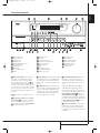 5
5
-
 6
6
-
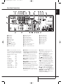 7
7
-
 8
8
-
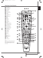 9
9
-
 10
10
-
 11
11
-
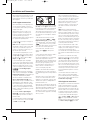 12
12
-
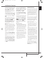 13
13
-
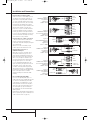 14
14
-
 15
15
-
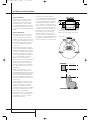 16
16
-
 17
17
-
 18
18
-
 19
19
-
 20
20
-
 21
21
-
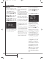 22
22
-
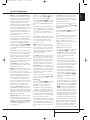 23
23
-
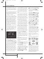 24
24
-
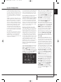 25
25
-
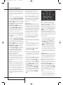 26
26
-
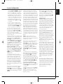 27
27
-
 28
28
-
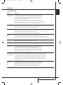 29
29
-
 30
30
-
 31
31
-
 32
32
-
 33
33
-
 34
34
-
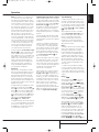 35
35
-
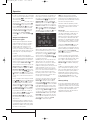 36
36
-
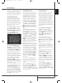 37
37
-
 38
38
-
 39
39
-
 40
40
-
 41
41
-
 42
42
-
 43
43
-
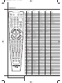 44
44
-
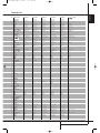 45
45
-
 46
46
-
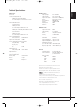 47
47
-
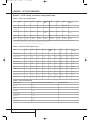 48
48
-
 49
49
-
 50
50


Harman Kardon AVR 145 Owner's manual
- Category
- AV receivers
- Type
- Owner's manual
Ask a question and I''ll find the answer in the document
Finding information in a document is now easier with AI
Related papers
-
Harman Kardon AVR340 Owner's manual
-
-
Harman Kardon LZR338 User manual
-
-
Harman Kardon AVR 140 Owner's manual
-
Harman Kardon AVR 347 User manual
-
Harman Kardon AVR 165 Owner's manual
-
-
-
Other documents
-
Harman-Kardon AVR 147 User manual
-
Harman/Kardon AVR 170 Owner's manual
-
-
-
-
AKG AVR 135/230 Datasheet
-
 Pacific Digital AVR 635 User manual
-
-
-
LG FA-3000AWE Owner's manual
