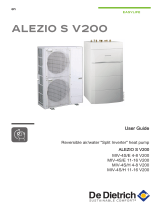
DeDietrich AWHP 8MR–EMC 24/28 MI HYBRIDE User manual

Category
Heat pumps
Type
User manual
en
User Manual
Hybrid heat pump
Alezio G hybrid
AWHP 4MR–EMC 24/28 MI HYBRIDE
AWHP 4MR–EMC 34/39 MI HYBRIDE
AWHP 6MR–EMC 24/28 MI HYBRIDE
AWHP 6MR–EMC 34/39 MI HYBRIDE
AWHP 8MR–EMC 24/28 MI HYBRIDE
AWHP 8MR–EMC 34/39 MI HYBRIDE
Dear Customer,
Thank you very much for buying this appliance.
Please read through the manual carefully before using the product, and keep it in a safe place for later reference.
In order to ensure continued safe and efficient operation we recommend that the product is serviced regularly. Our service and
customer service organisation can assist with this.
We hope you enjoy years of problem-free operation with the product.
Contents
1 Safety . . . . . . . . . . . . . . . . . . . . . . . . . . . . . . . . . . . . . . . . . . . . . . . . . . . . . . . . . . . . . . . . . . . . . . . . . . 5
1.1 General safety instructions . . . . . . . . . . . . . . . . . . . . . . . . . . . . . . . . . . . . . . . . . . . . . . . . . . . . . . 5
1.2 Recommendations . . . . . . . . . . . . . . . . . . . . . . . . . . . . . . . . . . . . . . . . . . . . . . . . . . . . . . . . . . . . 7
1.3 Specific safety instructions . . . . . . . . . . . . . . . . . . . . . . . . . . . . . . . . . . . . . . . . . . . . . . . . . . . . . . 9
1.3.1 Refrigerant fluid R410A . . . . . . . . . . . . . . . . . . . . . . . . . . . . . . . . . . . . . . . . . . . . . . . . . . 9
1.4 Liabilities . . . . . . . . . . . . . . . . . . . . . . . . . . . . . . . . . . . . . . . . . . . . . . . . . . . . . . . . . . . . . . . . . . . 11
1.4.1 User's liability . . . . . . . . . . . . . . . . . . . . . . . . . . . . . . . . . . . . . . . . . . . . . . . . . . . . . . . . . 11
1.4.2 Installer's liability . . . . . . . . . . . . . . . . . . . . . . . . . . . . . . . . . . . . . . . . . . . . . . . . . . . . . . .11
1.4.3 Manufacturer's liability . . . . . . . . . . . . . . . . . . . . . . . . . . . . . . . . . . . . . . . . . . . . . . . . . . 11
2 About this manual . . . . . . . . . . . . . . . . . . . . . . . . . . . . . . . . . . . . . . . . . . . . . . . . . . . . . . . . . . . . . . . . . . . . . . . . . . . . . . . . . . 13
2.1 General . . . . . . . . . . . . . . . . . . . . . . . . . . . . . . . . . . . . . . . . . . . . . . . . . . . . . . . . . . . . . . . . . . . . . . . . . . . . . . . . . . . . . 13
2.2 Additional documentation . . . . . . . . . . . . . . . . . . . . . . . . . . . . . . . . . . . . . . . . . . . . . . . . . . . . . . . . . . . . . . . . . . . . . . . 13
2.3 Symbols used . . . . . . . . . . . . . . . . . . . . . . . . . . . . . . . . . . . . . . . . . . . . . . . . . . . . . . . . . . . . . . . . . . . . . . . . . . . . . . . . 13
2.3.1 Symbols used in the manual . . . . . . . . . . . . . . . . . . . . . . . . . . . . . . . . . . . . . . . . . . . . . . . . . . . . . . . . . . . . . 13
2.3.2 Symbols used on the appliance . . . . . . . . . . . . . . . . . . . . . . . . . . . . . . . . . . . . . . . . . . . . . . . . . . . . . . . . . . .13
3 Technical specifications . . . . . . . . . . . . . . . . . . . . . . . . . . . . . . . . . . . . . . . . . . . . . . . . . . . . . . . . . . . . . . . . . . . . . . . . . . . . . 14
3.1 Homologations . . . . . . . . . . . . . . . . . . . . . . . . . . . . . . . . . . . . . . . . . . . . . . . . . . . . . . . . . . . . . . . . . . . . . . . . . . . . . . . 14
3.1.1 Directives . . . . . . . . . . . . . . . . . . . . . . . . . . . . . . . . . . . . . . . . . . . . . . . . . . . . . . . . . . . . . . . . . . . . . . . . . . . .14
3.1.2 Certifications . . . . . . . . . . . . . . . . . . . . . . . . . . . . . . . . . . . . . . . . . . . . . . . . . . . . . . . . . . . . . . . . . . . . . . . . . 14
3.1.3 Unit categories . . . . . . . . . . . . . . . . . . . . . . . . . . . . . . . . . . . . . . . . . . . . . . . . . . . . . . . . . . . . . . . . . . . . . . . .14
3.1.4 Factory test . . . . . . . . . . . . . . . . . . . . . . . . . . . . . . . . . . . . . . . . . . . . . . . . . . . . . . . . . . . . . . . . . . . . . . . . . . 14
3.2 Technical data . . . . . . . . . . . . . . . . . . . . . . . . . . . . . . . . . . . . . . . . . . . . . . . . . . . . . . . . . . . . . . . . . . . . . . . . . . . . . . . .15
3.2.1 Boiler specifications . . . . . . . . . . . . . . . . . . . . . . . . . . . . . . . . . . . . . . . . . . . . . . . . . . . . . . . . . . . . . . . . . . . .15
3.2.2 Heat pump . . . . . . . . . . . . . . . . . . . . . . . . . . . . . . . . . . . . . . . . . . . . . . . . . . . . . . . . . . . . . . . . . . . . . . . . . . . 16
3.2.3 Weight . . . . . . . . . . . . . . . . . . . . . . . . . . . . . . . . . . . . . . . . . . . . . . . . . . . . . . . . . . . . . . . . . . . . . . . . . . . . . . 17
3.2.4 Technical data - Low-temperature heat pump combination heaters . . . . . . . . . . . . . . . . . . . . . . . . . . . . . . . 17
3.2.5 Hydraulic module circulating pump . . . . . . . . . . . . . . . . . . . . . . . . . . . . . . . . . . . . . . . . . . . . . . . . . . . . . . . . 19
4 Description of the product . . . . . . . . . . . . . . . . . . . . . . . . . . . . . . . . . . . . . . . . . . . . . . . . . . . . . . . . . . . . . . . . . . . . . . . . . . . . 20
4.1 General description . . . . . . . . . . . . . . . . . . . . . . . . . . . . . . . . . . . . . . . . . . . . . . . . . . . . . . . . . . . . . . . . . . . . . . . . . . . .20
4.2 Operating principle . . . . . . . . . . . . . . . . . . . . . . . . . . . . . . . . . . . . . . . . . . . . . . . . . . . . . . . . . . . . . . . . . . . . . . . . . . . . 20
4.3 Main components . . . . . . . . . . . . . . . . . . . . . . . . . . . . . . . . . . . . . . . . . . . . . . . . . . . . . . . . . . . . . . . . . . . . . . . . . . . . . 21
4.3.1 Main boiler components . . . . . . . . . . . . . . . . . . . . . . . . . . . . . . . . . . . . . . . . . . . . . . . . . . . . . . . . . . . . . . . . .21
4.3.2 Main components of the hydraulic module . . . . . . . . . . . . . . . . . . . . . . . . . . . . . . . . . . . . . . . . . . . . . . . . . . 22
4.4 Control panel description . . . . . . . . . . . . . . . . . . . . . . . . . . . . . . . . . . . . . . . . . . . . . . . . . . . . . . . . . . . . . . . . . . . . . . . 22
4.4.1 Description of the keys . . . . . . . . . . . . . . . . . . . . . . . . . . . . . . . . . . . . . . . . . . . . . . . . . . . . . . . . . . . . . . . . . 22
4.4.2 Description of the display . . . . . . . . . . . . . . . . . . . . . . . . . . . . . . . . . . . . . . . . . . . . . . . . . . . . . . . . . . . . . . . .23
5 Operation . . . . . . . . . . . . . . . . . . . . . . . . . . . . . . . . . . . . . . . . . . . . . . . . . . . . . . . . . . . . . . . . . . . . . . . . . . . . . . . . . . . . . . . . .25
5.1 Use of the control panel . . . . . . . . . . . . . . . . . . . . . . . . . . . . . . . . . . . . . . . . . . . . . . . . . . . . . . . . . . . . . . . . . . . . . . . . 25
5.1.1 Accessing the parameters of a PCB . . . . . . . . . . . . . . . . . . . . . . . . . . . . . . . . . . . . . . . . . . . . . . . . . . . . . . . 25
5.1.2 Browsing in the menus . . . . . . . . . . . . . . . . . . . . . . . . . . . . . . . . . . . . . . . . . . . . . . . . . . . . . . . . . . . . . . . . . 27
5.1.3 Accessing the User menu . . . . . . . . . . . . . . . . . . . . . . . . . . . . . . . . . . . . . . . . . . . . . . . . . . . . . . . . . . . . . . . 29
5.1.4 Accessing the COUNTERS / TIME PROG / CLOCK sub-menus PROG COOL . . . . . . . . . . . . . . . . . . . . . . 29
5.2 Start-up . . . . . . . . . . . . . . . . . . . . . . . . . . . . . . . . . . . . . . . . . . . . . . . . . . . . . . . . . . . . . . . . . . . . . . . . . . . . . . . . . . . . . 30
5.3 Shutdown . . . . . . . . . . . . . . . . . . . . . . . . . . . . . . . . . . . . . . . . . . . . . . . . . . . . . . . . . . . . . . . . . . . . . . . . . . . . . . . . . . . 30
5.3.1 Switching off the heating . . . . . . . . . . . . . . . . . . . . . . . . . . . . . . . . . . . . . . . . . . . . . . . . . . . . . . . . . . . . . . . . 30
5.3.2 Shutting down the cooling function . . . . . . . . . . . . . . . . . . . . . . . . . . . . . . . . . . . . . . . . . . . . . . . . . . . . . . . . 31
5.4 Frost Protection . . . . . . . . . . . . . . . . . . . . . . . . . . . . . . . . . . . . . . . . . . . . . . . . . . . . . . . . . . . . . . . . . . . . . . . . . . . . . . .31
6 Settings . . . . . . . . . . . . . . . . . . . . . . . . . . . . . . . . . . . . . . . . . . . . . . . . . . . . . . . . . . . . . . . . . . . . . . . . . . . . . . . . . . . . . . . . . . 32
6.1 List of parameters . . . . . . . . . . . . . . . . . . . . . . . . . . . . . . . . . . . . . . . . . . . . . . . . . . . . . . . . . . . . . . . . . . . . . . . . . . . . . 32
6.1.1 Menu List . . . . . . . . . . . . . . . . . . . . . . . . . . . . . . . . . . . . . . . . . . . . . . . . . . . . . . . . . . . . . . . . . . . . . . . . . . . . 32
6.1.2 Information menu . . . . . . . . . . . . . . . . . . . . . . . . . . . . . . . . . . . . . . . . . . . . . . . . . . . . . . . . . . . . . . . . . . . . . .32
6.1.3 PCB User Menu EHC-02 . . . . . . . . . . . . . . . . . . . . . . . . . . . . . . . . . . . . . . . . . . . . . . . . . . . . . . . . . . . . . . . . 33
6.1.4 PCB parameters SCB-04 . . . . . . . . . . . . . . . . . . . . . . . . . . . . . . . . . . . . . . . . . . . . . . . . . . . . . . . . . . . . . . . .35
6.1.5 COUNTERS / TIME PROG / CLOCK menus / PROG COOL . . . . . . . . . . . . . . . . . . . . . . . . . . . . . . . . . . . . 35
6.2 Setting the parameters . . . . . . . . . . . . . . . . . . . . . . . . . . . . . . . . . . . . . . . . . . . . . . . . . . . . . . . . . . . . . . . . . . . . . . . . . 37
6.2.1 Modifying the User parameters . . . . . . . . . . . . . . . . . . . . . . . . . . . . . . . . . . . . . . . . . . . . . . . . . . . . . . . . . . . 37
6.2.2 Activating Forcing of the cooling function . . . . . . . . . . . . . . . . . . . . . . . . . . . . . . . . . . . . . . . . . . . . . . . . . . . 37
Contents
7611444 - v02 - 11122015 3
6.2.3 Setting the room temperature set point in comfort mode . . . . . . . . . . . . . . . . . . . . . . . . . . . . . . . . . . . . . . . .39
6.2.4 Setting the domestic hot water temperature . . . . . . . . . . . . . . . . . . . . . . . . . . . . . . . . . . . . . . . . . . . . . . . . . 39
6.2.5 Activating Manual Forcing for heating . . . . . . . . . . . . . . . . . . . . . . . . . . . . . . . . . . . . . . . . . . . . . . . . . . . . . . 40
6.2.6 Setting the timer program . . . . . . . . . . . . . . . . . . . . . . . . . . . . . . . . . . . . . . . . . . . . . . . . . . . . . . . . . . . . . . . 40
7 Maintenance . . . . . . . . . . . . . . . . . . . . . . . . . . . . . . . . . . . . . . . . . . . . . . . . . . . . . . . . . . . . . . . . . . . . . . . . . . . . . . . . . . . . . . 43
7.1 General . . . . . . . . . . . . . . . . . . . . . . . . . . . . . . . . . . . . . . . . . . . . . . . . . . . . . . . . . . . . . . . . . . . . . . . . . . . . . . . . . . . . . 43
7.1.1 Troubleshooting . . . . . . . . . . . . . . . . . . . . . . . . . . . . . . . . . . . . . . . . . . . . . . . . . . . . . . . . . . . . . . . . . . . . . . .43
7.2 Standard inspection and maintenance operations . . . . . . . . . . . . . . . . . . . . . . . . . . . . . . . . . . . . . . . . . . . . . . . . . . . . 43
7.2.1 Checking the water pressure . . . . . . . . . . . . . . . . . . . . . . . . . . . . . . . . . . . . . . . . . . . . . . . . . . . . . . . . . . . . .44
7.3 Cleaning the casing . . . . . . . . . . . . . . . . . . . . . . . . . . . . . . . . . . . . . . . . . . . . . . . . . . . . . . . . . . . . . . . . . . . . . . . . . . . 44
7.4 Venting the system . . . . . . . . . . . . . . . . . . . . . . . . . . . . . . . . . . . . . . . . . . . . . . . . . . . . . . . . . . . . . . . . . . . . . . . . . . . . 44
8 Troubleshooting . . . . . . . . . . . . . . . . . . . . . . . . . . . . . . . . . . . . . . . . . . . . . . . . . . . . . . . . . . . . . . . . . . . . . . . . . . . . . . . . . . . .45
8.1 Error codes . . . . . . . . . . . . . . . . . . . . . . . . . . . . . . . . . . . . . . . . . . . . . . . . . . . . . . . . . . . . . . . . . . . . . . . . . . . . . . . . . . 45
8.1.1 Error codes on the PCB EHC-02 . . . . . . . . . . . . . . . . . . . . . . . . . . . . . . . . . . . . . . . . . . . . . . . . . . . . . . . . . . 45
8.1.2 Error codes on the second circuit PCB (SCB-04 PCB) . . . . . . . . . . . . . . . . . . . . . . . . . . . . . . . . . . . . . . . . . 47
8.1.3 Blocking of the boiler . . . . . . . . . . . . . . . . . . . . . . . . . . . . . . . . . . . . . . . . . . . . . . . . . . . . . . . . . . . . . . . . . . . 47
8.1.4 Locking of the boiler . . . . . . . . . . . . . . . . . . . . . . . . . . . . . . . . . . . . . . . . . . . . . . . . . . . . . . . . . . . . . . . . . . . .48
8.2 Error history . . . . . . . . . . . . . . . . . . . . . . . . . . . . . . . . . . . . . . . . . . . . . . . . . . . . . . . . . . . . . . . . . . . . . . . . . . . . . . . . . .49
8.3 Troubleshooting . . . . . . . . . . . . . . . . . . . . . . . . . . . . . . . . . . . . . . . . . . . . . . . . . . . . . . . . . . . . . . . . . . . . . . . . . . . . . . 50
9 Decommissioning . . . . . . . . . . . . . . . . . . . . . . . . . . . . . . . . . . . . . . . . . . . . . . . . . . . . . . . . . . . . . . . . . . . . . . . . . . . . . . . . . . 52
9.1 Decommissioning procedure . . . . . . . . . . . . . . . . . . . . . . . . . . . . . . . . . . . . . . . . . . . . . . . . . . . . . . . . . . . . . . . . . . . . .52
10 Disposal . . . . . . . . . . . . . . . . . . . . . . . . . . . . . . . . . . . . . . . . . . . . . . . . . . . . . . . . . . . . . . . . . . . . . . . . . . . . . . . . . . . . . . . . . .53
10.1 Disposal and Recycling . . . . . . . . . . . . . . . . . . . . . . . . . . . . . . . . . . . . . . . . . . . . . . . . . . . . . . . . . . . . . . . . . . . . . . . . .53
11 Environmental . . . . . . . . . . . . . . . . . . . . . . . . . . . . . . . . . . . . . . . . . . . . . . . . . . . . . . . . . . . . . . . . . . . . . . . . . . . . . . . . . . . . . 54
11.1 Energy savings . . . . . . . . . . . . . . . . . . . . . . . . . . . . . . . . . . . . . . . . . . . . . . . . . . . . . . . . . . . . . . . . . . . . . . . . . . . . . . . 54
12 Warranty . . . . . . . . . . . . . . . . . . . . . . . . . . . . . . . . . . . . . . . . . . . . . . . . . . . . . . . . . . . . . . . . . . . . . . . . . . . . . . . . . . . . . . . . . 55
12.1 General . . . . . . . . . . . . . . . . . . . . . . . . . . . . . . . . . . . . . . . . . . . . . . . . . . . . . . . . . . . . . . . . . . . . . . . . . . . . . . . . . . . . . 55
12.2 Terms of warranty . . . . . . . . . . . . . . . . . . . . . . . . . . . . . . . . . . . . . . . . . . . . . . . . . . . . . . . . . . . . . . . . . . . . . . . . . . . . . 55
13 Appendix . . . . . . . . . . . . . . . . . . . . . . . . . . . . . . . . . . . . . . . . . . . . . . . . . . . . . . . . . . . . . . . . . . . . . . . . . . . . . . . . . . . . . . . . . 56
13.1 Product fiche . . . . . . . . . . . . . . . . . . . . . . . . . . . . . . . . . . . . . . . . . . . . . . . . . . . . . . . . . . . . . . . . . . . . . . . . . . . . . . . . . 56
13.2 Package fiche . . . . . . . . . . . . . . . . . . . . . . . . . . . . . . . . . . . . . . . . . . . . . . . . . . . . . . . . . . . . . . . . . . . . . . . . . . . . . . . . 56
Contents
4 7611444 - v02 - 11122015
1 Safety
1.1 General safety instructions
Danger
This appliance can be used by children aged from 8
years and above and persons with reduced physical,
sensory or mental capabilities or lack of experience
and knowledge if they have been given supervision or
instruction concerning use of the appliance in a safe
way and understand the hazards involved. Children
shall not play with the appliance. Cleaning and user
maintenance shall not be made by children without
supervision.
Danger
In the event of a refrigerant leakage:
1. Switch off the appliance.
2. Open the windows.
3. Do not use a naked flame, do not smoke, do not
operate electrical contacts.
4. Avoid contact with the refrigerant. Danger of frost
injuries.
5. Evacuate the property.
6. Contact a qualified professional.
Danger
If you smell gas:
1. Do not use naked flames, do not smoke and do
not operate electrical contacts or switches (door
bell, lighting, motor, lift etc.).
2. Shut off the gas supply.
3. Open the windows.
4. Evacuate the property.
5. Contact a qualified installer.
Danger
If you smell flue gases:
1. Switch the boiler off.
2. Open the windows.
3. Evacuate the property.
4. Contact a qualified installer.
Danger of electric shock
Before any work, switch off the mains supply to the
heat pump.
Caution
Installation of the heat pump must be done by a quali
fied professional in accordance with prevailing local
and national regulations.
1 Safety
7611444 - v02 - 11122015 5
Warning
Do not touch the refrigeration connection pipes with
your bare hands while the heat pump is running. Dan
ger of burn or frost injury.
Warning
Do not touch the radiators for long periods. Depending
on the heat pump settings, the temperature of the ra
diators may exceed 60°C.
Warning
Do not touch the flue gas pipes. Depending on the
boiler settings, the temperature of the flue gas pipes
can rise to over 60°C.
Warning
In order to limit the risk of being scalded, the installa
tion of a thermostatic mixing valve on the domestic hot
water flow pipes is obligatory.
Take precautions with the domestic hot water. De
pending on the heat pump settings, the domestic hot
water temperature may exceed 65°C.
Note
Respect the minimum and maximum water inlet pres
sure to ensure correct operation of the heat pump: re
fer to the chapter Technical Specifications.
Caution
Only genuine spare parts may be used.
Warning
Only qualified professionals are authorised to work on
the heat pump and the heating system.
Note
Insulate the pipes to reduce heat losses to a mini
mum.
Caution
Ensure that the boiler is regularly serviced. Contact a
qualified installer or arrange a maintenance contract
for the servicing of the boiler.
Warning
Do not touch the flue gas pipes. Depending on the
boiler settings, the temperature of the flue gas pipes
can rise to over 60°C.
Note
Regularly check for the presence of water and pres
sure in the heating installation.
1 Safety
6 7611444 - v02 - 11122015
Caution
The system must satisfy each point in the rules in
force in the country that govern works and interven
tions in individual homes, blocks of flats or other build
ings.
Note
Heating water and domestic water must not come into
contact with each other.
Electrical connection
Caution
The heat pump must always be connected to the
protective earthing.
Earthing must comply with the prevailing installation
standards.
Earth the appliance before making any electrical
connections.
For the type and calibre of the protective equipment:
refer to the chapter Recommended Cable Cross-sec
tions in the Installation and Service Manual.
Caution
A disconnection method must be allowed in the fixed
pipes in accordance with the rules on installation in
force in the country.
Caution
If a power cord comes with the appliance and it turns
out to be damaged, it must be replaced by the manu
facturer, its after sales service or persons with similar
qualifications in order to obviate any danger.
Caution
In order to prevent any danger owing to the unexpec
ted reset of the thermal circuit breaker, this appliance
must not be powered through an external switch, such
as a timer, or be connected to a circuit which is regu
larly switched on and off by the electricity provider.
Note
This manual can also be found on our internet site.
1.2 Recommendations
Caution
Install the hydraulic module and the boiler for the hy
brid system in a location protected from freezing.
Caution
If the home is unoccupied for a long period and there
is a risk of frost, drain the hybrid system.
Note
Keep the hybrid system accessible at all times.
1 Safety
7611444 - v02 - 11122015 7
Note
Never remove or cover labels and data plates affixed
to the appliances. Labels and data plates must be
legible throughout the entire lifetime of the appliance.
Immediately replace damaged or illegible instructions
and warning stickers.
Note
Remove the casing only to perform maintenance and
repair work. Put the casing back in place after mainte
nance and repair work.
Warning
Only qualified persons are authorised to assemble, in
stall and maintain the installation.
Warning
The hybrid heat pump (heat pump and boiler) must be
disassembled and disposed of by a qualified installer
in accordance with local and national regulations.
Warning
If the mains lead is damaged, it must be replaced by
the original manufacturer, the manufacturer's dealer
or another suitably skilled person to prevent hazard
ous situations from arising.
Caution
The hybrid system should be in Summer or Frost Pro
tection mode rather than switched off to guarantee the
following functions:
Anti blocking of pumps
Frost Protection
Note
Regularly check the presence of water and pressure
in the heating installation.
Note
Keep this document close to the place where the ap
pliance is installed.
Caution
Do not make any modifications to the hybrid system
without the written consent of the manufacturer.
Caution
Do not neglect to service the hybrid system. Contact a
qualified professional or take out a maintenance con
tract for the annual servicing of the hybrid system.
1 Safety
8 7611444 - v02 - 11122015
1.3 Specific safety instructions
Warning
Refrigerant fluid and pipes:
Use only R410A refrigerant fluid to fill the installa
tion.
Use tools and pipe components especially designed
for use with R410A refrigerant fluid.
Use copper pipes deoxidised with phosphorus to
carry the refrigerant fluid.
Store the refrigerant connection pipes away from
dust and humidity (risk of damage to the compres
sor).
Do not use a load cylinder.
Protect the heat pump components, including the in
sulation and structural elements. Do not overheat
the pipes as brazed components may cause dam
age.
Contact between the refrigerant fluid and a flame
may result in emissions of toxic gases.
1.3.1 Refrigerant fluid R410A
Hazard identification
Effects harmful to health:
The vapours are heavier than air and may lead to asphyxia
owing to reduced oxygen levels.
Liquefied gas: contact with the liquid may cause serious
frost burn and eye injuries.
Product classification: this product is not classified as a
"hazardous preparation" according to European Union reg
ulations.
If the R410A refrigerant is mixed with air, it may cause pres
sure surges in the refrigeration pipes and lead to an explo
sion and other hazards.
Composition of / Information on the ingredients
Chemical nature: R-410A is composed of Difluoromethane
R32 and Pentafluoroethane R125
Tab.1 Composition of R-410A fluid
Name Proportion Number CE Number CAS
Difluoromethane R32 50% 200–839–4 75-10-5
Pentafluoroethane R125 50% 206-557-8 354-33-6
The Global-Warming Potential of R410A gas is 2087.5.
1 Safety
7611444 - v02 - 11122015 9
Tab.2 Precautions for use
First aid If inhaled:
Evacuate the subject from the contaminated area and take him into the
open air.
If feeling unwell: call a doctor.
In the event of contact with the skin:
Treat frost injuries like burns. Rinse with copious amounts of tepid water,
do not remove clothing (risk of adhesion to the skin).
If skin burns appear, call a doctor immediately.
In the event of contact with the eyes:
Rinse immediately with water, holding the eyelids well apart (for at least 15
minutes).
Consult an ophthalmologist immediately.
Fire prevention meas
ures
Appropriate extinguishing agents: All extinguishing agents can be used.
Inappropriate extinguishing agents: none to our knowledge. In the event of
fire nearby, use the appropriate extinguishing agents.
Specific hazards:
Rise in pressure: in the presence of air, an inflammable mixture may form
under certain temperature and pressure conditions.
Toxic and corrosive vapours may be released by the effect of the heat.
Special intervention methods: cool the volumes exposed to heat with water
spray.
Protection of the firemen:
Full self-contained breathing apparatus.
Complete body protection.
In the event of acciden
tal spillage
Individual precautions:
Avoid contact with the skin and eyes.
Do not intervene without appropriate protective equipment.
Do not inhale the vapours.
Evacuate the hazardous area.
Stop the leakage.
Eradicate all sources of ignition.
Ventilate the spillage area mechanically.
Cleaning / decontamination: allow any residual product to evaporate.
In the event of contact with the eyes: Rinse immediately with water, holding
the eyelids well apart (for at least 15 minutes). Consult an ophthalmologist
immediately.
Handling Technical measures: ventilation
Precautions to be taken:
No smoking.
Prevent the build-up of electrostatic charges.
Work in a well ventilated place.
Personal protection Respiratory protection:
If ventilation is insufficient: AX type cartridge mask.
In confined spaces: self-contained breathing apparatus.
Hand protection: protective gloves in leather or nitrile rubber.
Eye protection: safety glasses with side protection.
Skin protection: clothing made principally of cotton
Industrial hygiene: do not drink, eat or smoke at the place of work.
1 Safety
10 7611444 - v02 - 11122015
Considerations on dis
posal
Note
Disposal must be done in compliance with prevailing local
and national regulations.
Product waste: consult the manufacturer or the supplier for information on
recovery or recycling.
Soiled packaging: reuse or recycle after decontamination. Destroy in au
thorised installations.
Regulation European Regulation No. EC 842/2006: fluorinated greenhouse gases un
der the Kyoto Protocol.
1.4 Liabilities
1.4.1 User's liability
To guarantee optimum operation of the system, you must
abide by the following instructions:
Read and follow the instructions given in the manuals pro
vided with the appliance.
Call on a qualified professional to carry out installation and
initial commissioning.
Get your installer to explain your installation to you.
Have the required inspections and maintenance carried out
by a qualified installer.
Keep the instruction manuals in good condition close to the
appliance.
1.4.2 Installer's liability
The installer is responsible for the installation and initial com
missioning of the appliance. The installer must abide by the
following instructions:
Read and follow the instructions given in the manuals pro
vided with the appliance.
Install the appliance in compliance with prevailing legisla
tion and standards.
Carry out initial commissioning and any checks necessary.
Explain the installation to the user.
If maintenance is necessary, warn the user of the obliga
tion to check the appliance and keep it in good working or
der.
Give all the instruction manuals to the user.
1.4.3 Manufacturer's liability
Our products are manufactured in compliance with the re
quirements of the various Directives applicable. They are
therefore delivered with the marking and any documents
necessary. In the interests of the quality of our products, we
strive constantly to improve them. We therefore reserve the
right to modify the specifications given in this document.
Our liability as manufacturer may not be invoked in the fol
lowing cases:
1 Safety
7611444 - v02 - 11122015 11
Failure to abide by the instructions on installing the appli
ance.
Failure to abide by the instructions on using the appliance.
Faulty or insufficient maintenance of the appliance.
1 Safety
12 7611444 - v02 - 11122015
2 About this manual
2.1 General
This manual is intended for the user of a Alezio G hybrid hybrid heat
pump.
2.2 Additional documentation
These instructions contain information on the indoor module for the hybrid
heat pump (hydraulic module + boiler), and some information on the out
door unit.
For additional information on the outdoor unit, refer to the manual provided
with that unit.
2.3 Symbols used
2.3.1 Symbols used in the manual
This manual uses various danger levels to draw attention to special in
structions. We do this to improve user safety, to prevent problems and to
guarantee correct operation of the appliance.
Danger
Risk of dangerous situations that may result in serious personal
injury.
Danger of electric shock
Risk of electric shock.
Warning
Risk of dangerous situations that may result in minor personal in
jury.
Caution
Risk of material damage.
Note
Please note: important information.
See
Reference to other manuals or pages in this manual.
2.3.2 Symbols used on the appliance
1Alternating current
2Protective earthing
1Before installing and commissioning the appliance, carefully read
the instruction manuals provided
2Dispose of used products in an appropriate recovery and recycling
structure
Fig.1 Symbols used on the appliance
MW-6000066-3
1 2
Fig.2 Symbols used on the data plate
1
2MW-6000691-1
2 About this manual
7611444 - v02 - 11122015 13
3 Technical specifications
3.1 Homologations
3.1.1 Directives
This product complies with the requirements of the following European Di
rectives and Standards:
Low Voltage Directive 2006/95/EC
Generic standard: EN 60335–1
Relevant Standard: EN 60335-2-40
Electromagnetic Compatibility Directive 2004/108/EC
Generic standards: EN 61000-6-3, EN 61000-6-1
Relevant Standard: EN 55014
Pressure Equipment Directive 97/23/EC, Article 3, paragraph 3
This product conforms to the requirements of European Directive
2009/125/EC on the ecodesign of energy-related products.
In addition to the legal requirements and guidelines, the supplementary
guidelines in this manual must also be followed.
Supplements or subsequent regulations and guidelines that are valid at
the time of installation shall apply to all regulations and guidelines speci
fied in this manual.
3.1.2 Certifications
Tab.3 Certifications
CE identification number PIN 0063CM3019
NOx class 5 (EN 15502–1)
Type of connection
3.1.3 Unit categories
Tab.4 Unit categories
Category Gas type Connection pressure
(mbar)
II2H3B/P G20 (H gas)
G30/G31 (butane/propane)
20
30
3.1.4 Factory test
Before leaving the factory, each indoor module is tested on the following
items:
Tightness of the heating circuit
Electrical safety
Tightness of the refrigerant circuit
3 Technical specifications
14 7611444 - v02 - 11122015
3.2 Technical data
3.2.1 Boiler specifications
Tab.5 General
Alezio G hybrid
Nominal output (Pn)
Central heating operation (80°C/60°C)
min–max
(1)
kW
Nominal output (Pn)
DHW operation
min-max
(1)
kW
(1) Factory setting
Tab.6 Details of gas and flue gas
Alezio G hybrid
Central heating chimney efficiency (Hi)
(80/60°C) at 20°C amb.
%
Central heating chimney losses (Hi)
(80/60°C) at 20°C amb.
%
Tab.7 Central heating circuit data
Alezio G hybrid
Water content l
Water operating pressure (PMS) max bar
Water temperature max °C
Operating temperature max °C
Tab.8 DHW circuit data
Alezio G hybrid
Specific hot water flow rate D (60°C) l/min
Specific hot water flow rate D (40°C) l/min
Flow rate threshold(1) min l/min
Operating pressure (Pmw) bar
(1) Minimum amount of water that comes out of the tap to make the boiler start.
Tab.9 Electrical data
Alezio G hybrid
Supply voltage VAC
Power consumption – full load max
(1)
W
(1) Factory setting
Tab.10 Other data
Alezio G hybrid
Total weight (empty) kg
Average acoustic level (1) at a distance of one metre from the boiler Central heating operation
DHW operation
dB(A)
(1) Maximum.
3 Technical specifications
7611444 - v02 - 11122015 15
3.2.2 Heat pump
Maximum operating pressure: 0.3 MPa (3 bar)
Tab.11 Conditions of use
Water (°C) Outside air (°C)
Limit operating temperatures in heating
mode
+18 / +60 AWHP 4 MR, AWHP 6 MR-2 : -15 / +35
Other models: -20 / +35
Limit operating temperatures in cooling
mode
+7 / +25 +7 / +40
Tab.12 Heating mode: outside air temperature +7°C, water temperature at the outlet +35°C. Performances in accordance with
EN 14511-2.
Measurement type Unit AWHP 4 MR AWHP 6 MR-2 AWHP 8 MR-2
Heat output kW 3.94 5.79 7.90
Coefficient of perform
ance (COP)
4.53 4.05 4.35
Absorbed electrical
power
kWe 0.87 1.43 1.82
Nominal water flow rate
(ΔT = 5K)
m3/hour 0.68 1.00 1.36
Tab.13 Heating mode: outside air temperature +2°C, water temperature at the outlet +35°C. Performances in accordance with
EN 14511-2.
Measurement type Unit AWHP 4 MR AWHP 6 MR-2 AWHP 8 MR-2
Heat output kW 3.89 3.65 6.80
Coefficient of perform
ance (COP)
3.35 3.23 3.30
Absorbed electrical
power
kWe 1.16 1.13 2.06
Tab.14 Cooling mode: outside air temperature +35°C, water temperature at the outlet +18°C. Performances in accordance with
EN 14511-2.
Measurement type Unit AWHP 4 MR AWHP 6 MR-2 AWHP 8 MR-2
Cooling output kW 3.84 4.69 7.90
Energy efficiency ratio
(EER)
4.83 4.09 3.99
Absorbed electrical
power
kWe 0.72 1.15 2.00
Tab.15 Common specifications
Measurement type Unit AWHP 4 MR AWHP 6 MR-2 AWHP 8 MR-2
Total dynamic head at
nominal flow rate
kPa 67 63 44
Nominal air flow rate m3/hour 2100 2100 3300
Power voltage of the
outdoor unit
V 230 230 230
Start-up amperage A 5 5 5
Maximal amperage A 13 13 19
Acoustic power - In
side (1)
dB(A) 48.8 48.8 48.8
3 Technical specifications
16 7611444 - v02 - 11122015
Measurement type Unit AWHP 4 MR AWHP 6 MR-2 AWHP 8 MR-2
Acoustic power - Out
side(1)
dB(A) 62.4 64.8 66.7
Refrigerant fluid
R410A
kg 2.1 2.1 3.2
Refrigerant connection
(Liquid - Gas)
inch 1/4 - 1/2 1/4 - 1/2 3/8 - 5/8
Max. pre-loaded length m 10 10 10
International protection
code (electrical)
IP X2D IP X2D IP X2D
(1) Noise radiated by the envelope - Test run in accordance with the NF EN 12102 standard, temperature conditions: air 7°C, water 55°C
3.2.3 Weight
Tab.16 Hydraulic module
Weight (empty) kg 22
Note
For the weight of the boiler, refer to the Other Data table in the
Boiler technical characteristics section.
Tab.17 Outdoor unit
Weight (empty) Unit AWHP 4 MR AWHP 6 MR-2 AWHP 8 MR-2
Outdoor unit kg 42 42 75
3.2.4 Technical data - Low-temperature heat pump combination
heaters
Tab.18 Technical parameters for heat pump combination heaters (parameters declared for medium-temperature application)
Product name AWHP 4MR–
EMC 24/28 MI
HYBRIDE
AWHP 6MR–
EMC 24/28 MI
HYBRIDE
AWHP 8MR–
EMC 24/28 MI
HYBRIDE
Air-to-water heat pump Yes Yes Yes
Water-to-water heat pump No No No
Brine-to-water heat pump No No No
Low-temperature heat pump No No No
Equipped with a supplementary heater Yes Yes Yes
Heat pump combination heater Yes Yes Yes
Rated heat output under average conditions(1)
Prated
kW 6 8 11
Rated heat output under colder conditions(1)
Prated
kW 5 6 9
Rated heat output under warmer conditions(1)
Prated
kW 3 5 6
Declared capacity for heating for part load at in
door temperature 20 °C and outdoor temperature
Tj
Tj
= -7 °C
Pdh
kW 2.9 3.5 5.6
Tj
= +2 °C
Pdh
kW 3.5 4.5 6.1
Tj
= +7 °C
Pdh
kW 3.9 4.8 6.4
Tj
= +12 °C
Pdh
kW 4.8 5.2 6.5
Tj
= bivalent temperature
Pdh
kW 3.5 4.5 6.1
3 Technical specifications
7611444 - v02 - 11122015 17
Product name AWHP 4MR–
EMC 24/28 MI
HYBRIDE
AWHP 6MR–
EMC 24/28 MI
HYBRIDE
AWHP 8MR–
EMC 24/28 MI
HYBRIDE
Tj
= operation limit temperature
Pdh
kW 2.8 3.6 5.6
Bivalent temperature
Tbiv
°C 2 2 2
Degradation co-efficient(2)
Cdh
1.0 1.0 1.0
Seasonal space heating energy efficiency under
average conditions
ƞs
% 150 133 135
Seasonal space heating energy efficiency under
colder conditions
ƞs
% 132 122 125
Seasonal space heating energy efficiency under
warmer conditions
ƞs
% 195 166 169
Declared coefficient of performance or primary
energy ratio for part load at indoor temperature
20 °C and outdoor temperature
Tj
Tj
= -7 °C
COPd
-
or
%
1.82 1.86 1.95
Tj
= +2 °C
COPd
-
or
%
3.88 3.40 3.49
Tj
= +7 °C
COPd
-
or
%
5.65 4.52 4.57
Tj
= +12 °C
COPd
-
or
%
9.33 6.70 6.33
Tj
= bivalent temperature
COPd
-
or
%
3.88 3.40 3.49
Tj
= operation limit temperature
COPd
-
or
%
1.47 1.52 1.63
Operation limit temperature for air-to-water
heat pumps
TOL
°C -10 -10 -10
Heating water operating limit temperature
WTOL
°C 80 80 80
Electrical power consumption
Off mode
POFF
kW 0.009 0.009 0.009
Thermostat-off mode
PTO
kW 0.049 0.049 0.049
Stand-by
PSB
kW 0.013 0.013 0.013
Crankcase heater mode
PCK
kW 0.055 0.055 0.055
Supplementary heater
Rated heat output(1)
Psup
kW 3.7 4.8 5.8
Type of energy input Gas Gas Gas
Other characteristics
Capacity control Variable Variable Variable
Sound power level, indoors - outdoors
LWA
dB 42 – 62 42 – 64 42 – 65
Annual energy consumption under average
conditions
QHE
kWh
GJ
2900
5
4312
7
5859
8
Annual energy consumption under colder con
ditions
QHE
kWh
GJ
3230
3
4236
3
6548
5
Annual energy consumption under warmer
conditions
QHE
kWh
GJ
887
0
1544
0
1904
0
3 Technical specifications
18 7611444 - v02 - 11122015
Product name AWHP 4MR–
EMC 24/28 MI
HYBRIDE
AWHP 6MR–
EMC 24/28 MI
HYBRIDE
AWHP 8MR–
EMC 24/28 MI
HYBRIDE
Rated air flow rate, outdoors for air-to-water
heat pumps
m3/h 2100 2100 3300
Declared load profile XL XL XL
Daily electricity consumption
Qelec
kWh 0.177 0.177 0.177
Annual electricity consumption
AEC
kWh 38 38 38
Water heating energy efficiency
ƞwh
% 85.95 85.95 85.95
Daily fuel consumption
Qfuel
kWh 0.000 0.000 0.000
Annual fuel consumption
AFC
GJ 17 17 17
(1) The rated heat output
Prated
is equal to the design load for heating
Pdesignh
, and the rated heat output of a supplementary heater
Psup
is equal to the supplementary capacity for heating
sup(Tj).
(2) If
Cdh
is not determined by measurement then the default degradation coefficient is
Cdh
= 0,9.
See
The back cover for contact details.
3.2.5 Hydraulic module circulating pump
Note
The benchmark for the most efficient circulating pumps is EEI ≤
0.20.
3 Technical specifications
7611444 - v02 - 11122015 19
4 Description of the product
4.1 General description
The hybrid heat pump comprises:
an indoor module for the production of heating circuit water
a reversible outdoor unit for the production of energy in heating mode
and in cooling mode.
The indoor module comprises:
a hydraulic module, which groups together the functions for the heat
pump's indoor module
a wall-mounted condensing gas boiler, installed on the front of the hy
draulic module
The indoor module and the outdoor unit are connected by means of refrig
erant and electrical connections.
The system offers the following advantages:
An extremely compact solution which can be easily integrated into the
most confined areas of any residence.
The heating circuit is housed in the insulated volume within the home.
Thanks to the DC inverter system, the hybrid heat pump modulates its
output to adapt to the needs of the residence.
The control system uses the outside sensor to adjust the temperature of
the heating circuit according to the outside temperature.
The outer casing of the hydraulic module is made of painted steel sheet
ing.
4.2 Operating principle
Heat pumps in the Alezio G hybrid range extract heat from the air and re
turn it to the heating circuit via the refrigerant. The efficiency of a heat
pump is expressed in the form of a coefficient of performance (COP), de
fined as the ratio between the heat provided and the power consumed.
The heat pump comprises an evaporator, a compressor, a condenser and
an expansion valve. The indoor module includes the condenser. The other
components (evaporator, compressor and expansion valve) are located in
the outdoor unit.
1. The refrigerant fluid in this circuit is converted from the liquid state to
the gaseous state in the evaporator, making it possible to recover heat
from the air.
2. The compressor increases the fluid pressure, which thus increases
the temperature.
3. In the condenser, the fluid transfers the heat to the heating circuit
while converting to the liquid state.
4. The refrigerant passes through the thermostatic expansion valve and
returns to the initial state at low pressure and low temperature before
returning to the evaporator.
4 Description of the product
20 7611444 - v02 - 11122015
  • Page 1 1
  • Page 2 2
  • Page 3 3
  • Page 4 4
  • Page 5 5
  • Page 6 6
  • Page 7 7
  • Page 8 8
  • Page 9 9
  • Page 10 10
  • Page 11 11
  • Page 12 12
  • Page 13 13
  • Page 14 14
  • Page 15 15
  • Page 16 16
  • Page 17 17
  • Page 18 18
  • Page 19 19
  • Page 20 20
  • Page 21 21
  • Page 22 22
  • Page 23 23
  • Page 24 24
  • Page 25 25
  • Page 26 26
  • Page 27 27
  • Page 28 28
  • Page 29 29
  • Page 30 30
  • Page 31 31
  • Page 32 32
  • Page 33 33
  • Page 34 34
  • Page 35 35
  • Page 36 36
  • Page 37 37
  • Page 38 38
  • Page 39 39
  • Page 40 40
  • Page 41 41
  • Page 42 42
  • Page 43 43
  • Page 44 44
  • Page 45 45
  • Page 46 46
  • Page 47 47
  • Page 48 48
  • Page 49 49
  • Page 50 50
  • Page 51 51
  • Page 52 52
  • Page 53 53
  • Page 54 54
  • Page 55 55
  • Page 56 56
  • Page 57 57
  • Page 58 58
  • Page 59 59
  • Page 60 60

DeDietrich AWHP 8MR–EMC 24/28 MI HYBRIDE User manual

Category
Heat pumps
Type
User manual

Ask a question and I''ll find the answer in the document

Finding information in a document is now easier with AI