Page is loading ...

Installation, Operation and Maintenance Instructions
300 °C Peak Fan Convection Oven - PF Model: 200 Litres
R38 Controller
PF 200 + R38 Controller
MEN-PF200-004_R38 (06-08-2019)

Contents
This manual is for guidance on the use of the Carbolite Gero product specified on the
front cover. This manual should be read thoroughly before unpacking and using the
furnace or oven. The model details and serial number are shown on the back of this
manual. Use the product for the purpose for which it is intended.
1.0 Symbols and Warnings 5
1.1 Switches and Lights 5
1.2 General Warnings 5
2.0 Installation 7
2.1 Unpacking and Handling 7
2.2 Siting and Setting Up 7
2.3 Electrical Connections 9
3.0 R38 Controller 11
3.1 PID control 11
3.2 Operating Cycle 11
3.3 Controller Operation 11
3.4 Calibration 11
3.5 Over-Temperature Control (if fitted) 12
3.6 Temperature Controller Replacement 12
4.0 2132 Over-Temperature Controller Description (if fitted) 13
4.1 Description 13
4.2 Operation 13
4.2.1 Controls 13
4.2.2 Operation 14
4.2.3 Over-Temperature Operation 14
4.2.4 Over-Temperature Alarm 14
4.2.5 Resetting the Over-Temperature Alarm 14
4.2.6 Sensor Break 14
4.3 Audible Alarm 15
4.4 Navigation Diagram 15
5.0 Operation 16
5.1 Operating Cycle 16
5.2 Over-Temperature Control (if fitted) 16
5.3 Vents 16
5.4 Temperature Uniformity 17
5.5 Explosive Vapours 17
5.6 Atmospheres 17
2

5.7 Interior Light (if fitted) 17
5.8 Solenoid Valve with Manual Switch (if fitted) 17
5.9 Variable Speed Fan (if fitted) 18
5.10 Exhaust Fan (if fitted) 18
5.11 Stoving and Curing (if fitted) 18
5.11.1 Pre-heater (if fitted) 18
5.12 Door Switch (if fitted) 19
6.0 Maintenance 20
6.1 General Maintenance 20
6.2 Maintenance Schedule 20
6.2.1 Cleaning 22
6.3 Calibration 22
6.4 After-Sales Service 22
6.5 Recommended Spare Parts and Spare Parts Kit 22
6.6 Power Adjustment 22
7.0 Repairs and Replacements 24
7.1 Safety Warning - Disconnection from Power Supply 24
7.2 Safety Warning - Refractory Fibre Insulation 24
7.3 Panel Removal 25
7.3.1 Side Panel 25
7.3.2 Internal Element Cover 25
7.4 Temperature Controller Replacement 26
7.5 Solid-State Relay Replacement 26
7.6 Thermocouple Replacement 26
7.7 Element Replacement 26
7.8 Fuse Replacement 27
8.0 Fault Analysis 28
A. Oven Does Not Heat Up 28
B. Oven Overheats 28
9.0 Wiring Diagrams 29
9.1 WV-11-00 29
9.2 WS-02-06 - Variable Speed Fan 30
9.3 WS-02-02 31
10.0 Fuses and Power Settings 32
10.1 Fuses 32
10.2 Power Settings 32
3


1.0 Symbols and Warnings
1.1 Switches and Lights
Instrument switch: when the instrument switch is operated the
temperature control circuit is energised.
Interior light: when the interior light switch is operated the interior
light illuminates.
Solenoid valve (if fitted): see section 5.8 for full details
Variable speed fan (if fitted): see section 5.9 for full details
Exhaust fan (if fitted): see section 5.10 for full details
Stoving and curing (if fitted): see section 5.11 for full details
1.2 General Warnings
DANGER – Electric shock. Read any warning printed next to this
symbol.
WARNING: Risk of fatal injury.
5
1.0 Symbols and Warnings

1.0 Symbols and Warnings
DANGER – Hot surface. Read any warning printed next to this
symbol.
WARNING: All surfaces of a product may be hot.
DANGER – Read any warning printed next to this symbol.
Caution – Double Pole/Neutral Fusing
6

2.0 Installation
2.1 Unpacking and Handling
Remove the shelves and runners from the packaging before attempting to move the
equipment.
When unpacking and handling the product, always lift it by its base. Do not use the door
or any other projecting cover or component to support the equipment when moving it.
Use two or more people to carry the product where possible.
Carefully remove any packing material from inside and around the product before use.
Avoid damaging the surrounding insulation when removing packing materials.
Locate the shelves and runners as required.
2.2 Siting and Setting Up
Place the product on a level surface in a well ventilated area.
Site away from other sources of heat and on a non-flammable surface that is resistant
to accidental spillage or hot materials.
The surface on which the equipment is mounted should be stable and not subject to
movement or vibrations.
The height of the mounting surface is important to avoid operator strain when loading
and unloading samples.
Unless otherwise stated elsewhere in this manual, ensure that there is at least 150
mm of free space around the back and sides of the product. Clear space is required
above the product to dissipate heat.
7
2.0 Installation

2.0 Installation
Ensure that the product is placed in such a way that it can be quickly switched off or
disconnected from the electrical supply.
Some models have protruding fan motor housings: these housings must be in an area
of good ventilation.
Under no circumstances should any objects be placed on top of the product.
Always ensure that any vents on the top of the product are clear of any
obstruction. Always ensure all cooling vents and cooling fans (if fitted) are
clear of any obstruction.
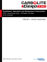
The ends of the runners should be inserted into the vertical
columns of holes simultaneously at the front and the back. The bar
should then be rotated through 90° in a downwards direction to
secure it in place. The shelves slide onto the runners such that the
spurs on the lower side of the shelf are under the bar at the back;
this prevents the shelf from tilting forwards when partially
withdrawn.
Do NOT use the oven floor as a shelf.
Key
A Runner
B Shelf
C Spur
8

2.3 Electrical Connections
Connection by a qualified electrician is recommended.
All models covered by this manual may be ordered for single phase A.C. supply, which
may be Live to Neutral non-reversible, Live to Neutral reversible or Live to Live.
Check the product rating label before connection. The supply voltage should agree with
the voltage on the label and the supply capacity should be sufficient for the current on
the label.
The supply should be fused at the next size equal to, or higher than the current on the
label. A table of the most common fuse ratings is also given towards the back of this
manual. When the mains cable is factory fitted, internal fuses are also fitted. It is
essential that the operator ensures that the product is correctly fused.
Products with a factory fitted supply cable are designed to be wired directly to an
isolator or fitted with a line plug.
Products without a factory fitted supply cable require a permanent connection to a
fused and isolated supply. The product's electrical access panel should be temporarily
removed, and connections made to the internal terminals.
If the product is to be connected by line plug. The plug should be within reach of the
operator and should be easy to remove.
When connecting the product to an isolating switch ensure that both conductors (single
phase) or on all live conductors (three phase), and should be within reach of the
operator.
The supply MUST incorporate an earth (ground).
Supply Terminal Label Cable Colour
Supply Types
Live - Neutral Reversible or Live-
Live
1-phase L Brown to live
to either power
conductor
(For USA 200-240V,
connect L1)
N Blue to neutral
to the other power
conductor
(For USA 200-240V,
connect L2)
PE Green/ Yellow to earth
(ground) to earth (ground)
Electrical Connection Details:
9
2.0 Installation

2.0 Installation
2- or
3-phase L1 Black to phase 1
L2 Black to phase 2
L3 Black to phase 3 (except 2-phase)
N Light Blue to neutral (except delta)
PE Green/ Yellow to earth (ground)
10

3.0 R38 Controller
3.1 PID control
This controller uses PID (Proportional Integral Derivative) temperature control. This
type of control uses a complex mathematical control system to adjust the heating
power and achieve the desired temperature.
3.2 Operating Cycle
This product is fitted with an instrument switch which cuts off power to the control
circuit.
Connect the product to the electrical supply.
The product has fan-assisted circulation which operates when the instrument switch is
switched on.
Operate the instrument switch to activate the temperature controller.
Adjust the temperature controller - see below.
To turn the product off, set the instrument switch to its off position. The controller
display will go blank. If the product is to be left unattended, isolate it from the electrical
supply.
3.3 Controller Operation
When switched on, the controller lights up, goes through a short test routine and then
displays the measured temperature and starts to control. The output light OUT1
indicates when heating is occurring.
To alter the setpoint, press the down arrow key once, “SPI” flashes. Then use the up
and down arrow keys to adjust the setpoint. Press the P key to accept.
3.4 Calibration
If the process requires an accurate temperature display it is possible to calibrate the
controller by entering a single temperature offset value as follows:
Please contact Carbolite Gero Service for detailed instructions on entering an offset in
the R38 Controller.
11
3.0 R38 Controller

3.0 R38 Controller
3.5 Over-Temperature Control (if fitted)
The over-temperature controller should typically be set at 15 °C above the main
controller. If an over-temperature condition occurs, check the main controller is
functioning correctly.
An over-temperature condition cuts off power to the heating elements. A light in the
over-temperature controller flashes. To reset this, refer to the over-temperature
control section of this manual.
3.6 Temperature Controller Replacement
Before handling the controller: wear an anti-static wrist strap or
otherwise avoid any possibility of damage to the unit by static electricity.
Refer to the detailed instructions supplied with the replacement
controller.
Disconnect the product from the electrical supply and remove the cover (see section
7.0).
Make a note of all the wiring connections before disconnecting the wires. Loosen the
screw that holds the controller body clamp in place. Use a flat screwdriver or similar
object to ease apart the two plastic lugs on the side of the clamp and pull the instrument
forward out of the front control panel.
Reconnect the wires according to the notes made – or see section 9.0 for wiring details.
Note: If the product features an R38 over-temperature controller, then this should
be replaced using the same method described.
12

4.0 2132 Over-Temperature Controller Description (if
fitted)
4.1 Description
Key
A Alarm Light
B Page
C Scroll
D Down
E Up
F Display
This over-temperature controller is fitted and supplied ready to use by Carbolite Gero.
It is a digital instrument with a latching alarm, requiring no additional panel controls.
The controller features easy setting of over-temperature setpoint and reading of
current temperature by the over-temperature sensor.
4.2 Operation
4.2.1 Controls
Most Carbolite Gero products are fitted with an instrument switch which cuts off power
to the controller and other parts of the control circuit.
To operate the controller, power must be supplied to the product and the instrument
switch must be on. If a time switch is included in the product circuit, this must be in the
'ON' position.
When an over-temperature condition occurs, the controller cuts the power to a
contactor, which in turn cuts power to the heating elements. Power is not restored until
the controller is 'reset'.
Some components will operate after the over-temperature feature isolates the power
supply e.g. cooling fans will continue to operate, provided that there is a power supply
to the product. In some cases the product may not do so, if other options (such as a
door switch) are fitted.
13
4.0 2132 Over-Temperature

4.0 2132 Over-Temperature
4.2.2 Operation
When switched on, the controller lights up, goes through a short test routine and then
displays the measured temperature or the over-temperature setpoint.
The page key allows access to parameter lists within the controller.
A single press of the page key displays the temperature units, normally set to °C;
further presses reveal the lists indicated in the navigation diagram.
The scroll key allows access to the parameters within a list. Some parameters are
display-only; others may be altered by the operator.
A single press of the scroll key in the 'Home' list displays the temperature units;
further presses reveal the parameters in the current list indicated in the navigation
diagram.
To return to the 'Home' list at any time, press page and scroll together, or wait
for 45 seconds.
The down and up keys are used to alter the setpoint or other parameter values.
4.2.3 Over-Temperature Operation
Use down and up to alter the over-temperature setpoint. This should normally be
set a little above the working temperature (for example 15 °C above). The product is
supplied with the over-temperature set at 15 °C above the furnace or oven maximum
working temperature.
Press scroll twice view the present temperature as measured by the over-
temperature controller. Press it twice, the first press shows the temperature units (°C).
4.2.4 Over-Temperature Alarm
If an over-temperature condition occurs, the OP2 indicator flashes and an alarm
message 2FSH also flashes, alternating with the setpoint. Power to the heating
elements is disconnected.
4.2.5 Resetting the Over-Temperature Alarm
To acknowledge the alarm press scroll and page together.
If the alarm is acknowledged while there is still an over-temperature condition, the OP2
indicator stops flashing but continues to glow. The 2FSH alarm continues to flash until
the over-temperature condition is cleared (by the temperature falling), when normal
operation resumes.
If the alarm is acknowledged when the temperature has dropped (or after the over-
temperature setpoint has been raised) so that the over-temperature condition no longer
exists, then the furnace or oven immediately resumes normal operation.
4.2.6 Sensor Break
The over-temperature cut-out system also operates if the over-temperature control
thermocouple breaks or becomes disconnected. The message S.br flashes where the
measured temperature is normally displayed.
14

4.3 Audible Alarm
If an audible alarm is supplied for use with the over-temperature controller, it is
normally configured to sound on over-temperature condition and to stop sounding when
the alarm is acknowledged as given in section 4.2.
Note: the alarm may sound during controller start-up.
4.4 Navigation Diagram
HL Home List Page Key Black = Progress
OTSP Over-Temperature
Setpoint Scroll Key
Dashed = Through to
other options
AL Access List For factory access to list and parameters not
available to the operator.
15
4.0 2132 Over-Temperature

5.0 Operation
5.0 Operation
5.1 Operating Cycle
The product is fitted with an instrument switch. The switch cuts off power to the
controllers and elements. The circulation fan will operate when the instrument switch is
on. An optional door switch may be fitted. If so, ensure that the door is closed to
operate the fans and heating elements.
Turn on the instrument switch to activate the temperature controllers. The controllers
illuminate and go through a short test cycle.
Over-Temperature option only. If the digital over-temperature option has not yet
been set as required, set and activate it according to the over-temperature controller
instructions.
The product will heat up according to the controller setpoint or program, unless a time
switch is fitted and switched off.
Over-Temperature option only. If the over-temperature circuit has tripped, an
indicator on the over-temperature controller flashes and the heating elements are
isolated. Find and correct the cause before resetting the over-temperature controller
according to the instructions supplied.
To switch the product off, turn off the instrument switch. If the product is to be left
unattended, isolate the electricity supply.
DO NOT switch off if the temperature is above 100 °C - damage could be caused to the
fan and motor. Adjust the controller to allow the temperature to fall.
5.2 Over-Temperature Control (if fitted)
The over-temperature controller should typically be set at 15 °C above the main
controller. If an over-temperature condition occurs, check the main controller is
functioning correctly.
An over-temperature condition cuts off power to the heating elements. A light in the
over-temperature controller flashes. To reset this, refer to the over-temperature
control section of this manual.
5.3 Vents
On the back of this product are two vents: inlet and exhaust. The inlet vent is covered by
a baffle that should be left in place.
The exhaust vent is closed by a butterfly valve that can be controlled from the front
panel. Rotate the knob clockwise to open the vent, anticlockwise to close.
In non-fan models there is only a small flow of air through the chamber. With fan
versions, fumes are pushed out through the exhaust vent by fan action and fresh air is
drawn in through the inlet vent.
16

5.4 Temperature Uniformity
Where accurate temperature control of the load is important, use the central part of the
chamber and place or distribute the load to allow free air circulation. Do not place loads
on the chamber floor: use the bottom shelf.
5.5 Explosive Vapours
Unless your product includes the stoving and curing option, this model is
not suitable for drying or heat treatment applications where vapours are
released that are combustible or which can form explosive mixtures with
air. Carbolite Gero manufactures other products suitable for these
applications.
5.6 Atmospheres
When an optional gas inlet is fitted, there is a label near the inlet saying "INERT GAS
ONLY". In practice, inert or oxidising gases may be used, but not combustible or toxic
gases.
The chamber is not gas tight, the gas usage may be high and the chamber is always
likely to contain some air. Residual oxygen of approximately 1% to 2% is to be
expected.
5.7 Interior Light (if fitted)
If fitted, the interior light is operated using the panel mounted switch.
It will only operate when the instrument switch is on.
5.8 Solenoid Valve with Manual Switch (if fitted)
If ordered the solenoid valve is operated using the panel mounted
switch. When the switch is in the 'ON' position the solenoid valve will
allow gas to
flow. Ensure the installation and use of the product does not create a hazardous
atmosphere. The workspace must have sufficient ventilation.
17
5.0 Operation

5.0 Operation
5.9 Variable Speed Fan (if fitted)
If fitted, the variable speed control is fitted in the air circulation fan circuit. A
panel mounted rotary dial is used to control the speed.
Please note that there is a minimum setting at which the fan motor starts up when the
product is switched on. It is recommended that the speed of the fan is not set below
50%, as there would be very little air flow around the chamber and also risk overheating
the fan motor.
5.10 Exhaust Fan (if fitted)
To operate the exhaust fan use the fan switch on the control panel; this is only
functional when the instrument switch is on.
The level of air exhaust can be controlled by adjusting the slider under the
exhaust box.
When the exhaust fan is turned on, there may be a drop in internal temperature before
the product recovers to the setpoint value.
The airflow should be adjusted to the minimum required by the process to reduce the
amount of energy wasted in heating air.
5.11 Stoving and Curing (if fitted)
The stoving and curing option adds an explosion relief panel and a powered
exhaust fan. With this option the exhaust fan operates continuously when the
product is switched on.
A pressure switch detects that there is sufficient air flow through the chamber. If the
pressure switch does not detect sufficient air flow, a fault light illuminates and heating is
disabled.
At least 610 mm free space must be left around the explosion relief panel to allow this
to break out if there is a rapid build up of pressure inside the chamber.
Please note that if the stoving and curing option is fitted, there may be an increase in
the power rating of the product. See the product rating label located on the side panel
of the product for correct power rating.
5.11.1 Pre-heater (if fitted)
Products with the stoving and curing option may also be fitted with a pre-heater that
pre-heats the incoming air to the same temperature set on the main controller.
The temperature of the pre-heater is controlled by the main controller, but measured
by a separate thermocouple.
18

5.12 Door Switch (if fitted)
If ordered, the door switch will isolate the heating elements and circulation fan. The
door switch is operated when the door is opened causing the heating elements and air
circulation fan to be switched off.
19
5.0 Operation

6.0 Maintenance
6.0 Maintenance
6.1 General Maintenance
Preventive rather than reactive maintenance is recommended. The type and frequency
depends on the product use; the following are recommended.
6.2 Maintenance Schedule
CUSTOMER
QUALIFIED PERSONNEL
DANGER! ELECTRIC SHOCK. Risk of fatal injury. Only electrically
qualified personnel should attempt these maintenance procedures.
Maintenance
Procedure Method
Frequency
Daily Weekly Monthly Bi-
Annually Annually
Safety
Over-Temperature Safety Circuit
(if fitted)
Set an over-temperature setpoint lower
than the displayed temperature and
check for an over-temperature alarm as
detailed in this manual
Over-Temperature Safety Circuit
(if fitted) Electrical measurement
Door Seal Visual inspection - check for splits or fray-
ing
Door Seal Replacement
Air Vent Check and clean if necessary
Electrical Safety (external) Visual check of external cables and plugs
Electrical Safety (internal) Physically check all connections and clean-
ing of the power plate area
Function
Temperature Calibration
Tested using certified equipment, fre-
quency dependent on the standard
required
Operational Check Check that all functions are working nor-
mally
Operational Check Thorough inspection and report incor-
porating a test of all functions
Performance
20
/