Page is loading ...

CONSUMER SERVICES TECHNICAL
EDUCATION GROUP PRESENTS
L-69
JOB AID
Part No. 8178071
GAS AND ELECTRIC
DRYERS
Model Numbers:
GGW9200L & GEW9200L
™

- ii -
WHIRLPOOL CORPORATION assumes no responsibility for any repairs made
on our products by anyone other than Authorized Service Technicians.
FORWARD
This Whirlpool Job Aid, “Duet™ Gas and Electric Dryers,” (Part No. 8178071), provides the
technician with information on the operation and service of the Gas and Electric Dryers. It is to be
used as a training Job Aid and Service Manual. For specific information on the model being
serviced, refer to the “Use and Care Guide,” or “Tech Sheet” provided with the dryer.
The Wiring Diagrams used in this Job Aid are typical and should be used for training purposes only.
Always use the Wiring Diagram supplied with the product when servicing the unit.
GOALS AND OBJECTIVES
The goal of this Job Aid is to provide detailed information that will enable the service technician to
properly diagnose malfunctions and repair the Whirlpool Gas and Electric Dryers.
The objectives of this Job Aid are to:
• Understand and follow proper safety precautions.
• Successfully troubleshoot and diagnose malfunctions.
• Successfully perform necessary repairs.
• Successfully return the Gas or Electric Dryer to its proper operational status.
Copyright © 2001, Whirlpool Corporation, Benton Harbor, MI 49022

- iii -
TABLE OF CONTENTS
GENERAL............................................................................................................................................. 1-1
Important Safety Information........................................................................................................... 1-1
Model & Serial Number Designations ............................................................................................. 1-2
Model & Serial Number Label And Tech Sheet Locations ............................................................. 1-3
Specifications .................................................................................................................................. 1-4
Warranty .......................................................................................................................................... 1-5
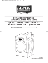
INSTALLATION INFORMATION ......................................................................................................... 2-1
Electrical Requirements For Electric Dryers ................................................................................... 2-1
Electrical Connections For Electric Dryers ..................................................................................... 2-3
Electrical Requirements For Gas Dryers ........................................................................................ 2-8
Gas Supply Requirements .............................................................................................................. 2-9
Optional Exhaust Information........................................................................................................ 2-10
Leveling The Dryer ........................................................................................................................ 2-10
Reversing The Door Swing ........................................................................................................... 2-11
Installing The Optional Pedestal ................................................................................................... 2-14
Optional Stack Kit (#8519492) ...................................................................................................... 2-16
PRODUCT OPERATION ...................................................................................................................... 3-1
COMPONENT ACCESS ....................................................................................................................... 4-1
Component Locations ..................................................................................................................... 4-1
Removing The Machine Control Electronics Board ........................................................................ 4-2
Removing The Console & The Touchpad Subassembly ................................................................ 4-4
Removing The Door Switch ............................................................................................................ 4-6
Removing The Thermal Fuse, Thermistor, Drive Motor, & Belt Switch .......................................... 4-7
Removing The Heater, The High-Limit Thermostat, & Thermal Cutoff......................................... 4-10
Removing The Belt, Drum, & Rollers ............................................................................................ 4-11
Removing The Drum Light Socket ................................................................................................ 4-14
Removing The Moisture Sensor ................................................................................................... 4-15
COMPONENT TESTING ...................................................................................................................... 5-1
Making Electrical Tests ................................................................................................................... 5-1
Drive Motor...................................................................................................................................... 5-2
Heater ............................................................................................................................................. 5-3
Thermal Fuse .................................................................................................................................. 5-4
Thermistor ....................................................................................................................................... 5-5
Thermal Cutoff (Electric Dryers Only) ............................................................................................. 5-6
Gas Valve (Gas Dryers Only) ......................................................................................................... 5-7
Moisture Sensor .............................................................................................................................. 5-8
Console Pushbuttons & LEDs......................................................................................................... 5-8
Door Switch ................................................................................................................................... 5-10
DIAGNOSIS AND TROUBLESHOOTING ........................................................................................... 6-1
Diagnosis ........................................................................................................................................ 6-1
Display Fault/Error Codes ......................................................................................................... 6-1
Diagnostic Tests ........................................................................................................................ 6-1
Keypad Test .............................................................................................................................. 6-2
Additional Tests ......................................................................................................................... 6-2
Troubleshooting Guide .................................................................................................................... 6-3
WIRING DIAGRAMS ............................................................................................................................ 7-1
Page

- iv -
— NOTES —

1-1
ELECTRICAL SHOCK HAZARD
Disconnect power before servicing.
Replace all panels before operating.
Failure to do so could result in death or
electrical shock.
Important safety messages have been pro-
vided in this Job Aid. Always read and obey all
safety messages.
IMPORTANT SAFETY INFORMATION
Your safety and the safety of others is very important.
This is the safety alert symbol.
This symbol alerts you to haz-
ards that can kill or hurt you
and others.
All safety messages will be preceded by the
safety alert symbol and the word “WARNING.”
All safety messages will identify the hazard, tell
you how to reduce the chance of injury, and tell
you what can happen if the instructions are not
followed.
WARNING
ELECTROSTATIC DISCHARGE
(ESD) SENSITIVE ELECTRONICS
ESD problems are present everywhere. ESD
may damage or weaken the electronic control
assembly. The new control assembly may ap-
pear to work well after repair is finished, but
failure may occur at a later date due to ESD
stress.
• Use an antistatic wrist strap. Connect the
wrist strap to a green ground connection
point or unpainted metal in the appliance;
or touch your finger repeatedly to a green
ground connection point or unpainted metal
in the appliance.
• Before removing the part from its pack-
age, touch the antistatic bag to a green
ground connection point or unpainted metal
in the appliance.
• Avoid touching electronic parts or terminal
contacts. Handle the electronic control
assembly by the edges only.
• When repackaging the failed electronic
control assembly in an antistatic bag, ob-
serve the above instructions.
GENERAL
FIRE HAZARD
Disconnect gas supply before servicing.
Replace all panels before operating.
Failure to do so could result in death or
electrical shock.
WARNING

1-2
MODEL & SERIAL NUMBER DESIGNATIONS
MODEL NUMBER (DRYER)
MODEL NUMBER (PEDESTAL)
SERIAL NUMBER (DRYER) SERIAL NUMBER (PEDESTAL)
MODEL NUMBER G E W 9200 L W 0
PRODUCT GROUP
G = Domestic Laundry Gold
PRODUCT IDENTIFICATION
E = Electric Dryer
G = Gas Dryer
FEATURE CODE
W = High Efficiency
FEATURE LEVEL
YEAR OF INTRODUCTION
L = 2002
COLOR CODE
W = White / Grey
Q = White / Blue
ENGINEERING CHANGE
0 = Basic, 1 = 1st Revision, 2 = 2nd Revision
MODEL NUMBER L A B 2 7 0 0 L Q 0
PRODUCT GROUP
L = Domestic Laundry
PRODUCT IDENTIFICATION
A = Laundry Accessory
FEATURE CODE
B = Pedestal Base
PRODUCT WIDTH
FILLER
FILLER
YEAR OF INTRODUCTION
COLOR CODE
K = Graphite (Laundry)
Q = White On White
T = Biscuit On Biscuit
ENGINEERING CHANGE
SERIAL NUMBER
M L 16 00036
MANUFACTURING SITE
MARION, OH
YEAR OF PRODUCTION
L = 2001
WEEK OF PRODUCTION
PRODUCT SEQUENCE NUMBER
SERIAL NUMBER C T L 01 10001
MANUFACTURING SITE
TAYLOR IND., MANSFIELD, OH
YEAR OF PRODUCTION
L = 2001
WEEK OF PRODUCTION
PRODUCT SEQUENCE NUMBER

1-3
MODEL & SERIAL NUMBER LABEL
AND TECH SHEET LOCATIONS
The Model/Serial Number label and Tech Sheet locations are shown below.
Tech Sheet Location
(Located Under Top Cover)
Model & Serial
Number Label Location

1-4
SPECIFICATIONS
BRAND Whirlpool Whirlpool Whirlpool Whirlpool
MODEL NUMBER GEW9200LW GEW9200LQ GGW9200LW GGW9200LQ
FUEL Electric Electric Gas Gas
CABINET COLOR White/Grey White/Blue White/Grey White/Blue
INSTALLATION OPTIONS
FREESTANDING
XXXX
PEDESTAL
XXXX
STACKABLE
XXXX
CAPACITY (cu ft)
7.0 7.0 7.0 7.0
CAPACITY NOMENCLATURE
SUPER CAPACITY SUPER CAPACITY SUPER CAPACITY SUPER CAPACITY
AUTO CYCLE TERMINATION
ENHANCED EH (Fuzzy Logic)
XXXX
SENSION CONTROL
XXXX
LINT HANDLING
FRONT SCREEN
XXXX
CONTROLS
Electronic Electronic Electronic Electronic
CONTROL LOCK OUT
XXXX
CONTROL TYPE PRIMARY
Rotary Rotary Rotary Rotary
CONTROL TYPE SECONDARY
Tap Touch Tap Touch Tap Touch Tap Touch
NON-HEATED DRY RACK
XXXX
MULTI-VENT OPTION
4 WAY 4 WAY 4 WAY 4 WAY
UTILITIES
FREQUENCY
60HZ 60HZ 60HZ 60HZ
MOTOR RATING
1/3 HP 1/3 HP 1/3 HP 1/3 HP
HEATER ELEMENT
5400W 5400W
GAS BTU
22,000 22,000
RATED AMPERAGE (ELECTRIC)
28 28
DIMENSIONS (UNCRATED)
HEIGHT OF TOP*
37 2/5 37 2/5 37 2/5 37 2/5
TOTAL HEIGHT*
37 2/5 37 2/5 37 2/5 37 2/5
WIDTH
27 27 27 27
DEPTH
ELECTRIC
30 3/4 30 3/4 30 3/4 30 3/4
GAS + 1 INCH
31 3/4 31 3/4 31 3/4 31 3/4
DEPTH DOOR OPEN
51 51 51 51
PRODUCT WEIGHT
143 143 143 143
WARRANTY
LABOR
1 Yr 1 Yr 1 Yr 1 Yr
PARTS
1 Yr 1 Yr 1 Yr 1 Yr
PORCELAIN TOP
5 Yr 5 Yr 5 Yr 5 Yr
MOTOR/ELEMENT/BURNER
1 Yr 1 Yr 1 Yr 1 Yr
CONTROLS
2 Yr 2 Yr 2 Yr 2 Yr

1-5
FULL ONE YEAR WARRANTY ON MECHANICAL
AND ELECTRICAL PARTS
For one year from the date of purchase, Whirlpool will pay for replacement
parts and repair labor for mechanical or electrical parts to correct defects
in materials or workmanship. Whirlpool will perform necessary adjust-
ments. Service must be provided by a Whirlpool Service Department in
Canada or an authorized agent.
NOTE: Exhausting this dryer with a plastic vent can void this warranty. See
the “Installation Instructions” for the exhaust requirements for this dryer.
LIMITED TWO YEAR WARRANTY ON SENSOR SMART™
ELECTRONIC CONTROL BOARD
For two years from the date of purchase, Whirlpool will replace the
electronic control board if defective in materials or workmanship. You will
be charged for labor after the first year.
LIMITED FIVE YEAR WARRANTY ON PORCELAIN TOP
For five years from the date of purchase, Whirlpool will replace parts for the
po top should it be perforated by rust or chippage.
PEDESTAL OPTION WARRANTY
WARRANTY
FULL ONE YEAR WARRANTY ON MECHANICAL PARTS
For one year from the date of purchase, when Pedestal is installed with this
dryer and operated according to the instructions provided in the Owner’s
Manual, supplier will repair or replace any mechanical parts if defective in
material or workmanship.

1-6
— NOTES —

2-1
ELECTRICAL REQUIREMENTS FOR ELECTRIC DRYERS
ELECTRICAL SHOCK HAZARD
Check with a qualified electrician if you
are in doubt as to whether the appliance
is properly grounded. Do not modify the
power supply cord plug. If it will not fit the
outlet, have a proper outlet installed by a
qualified electrician.
Improper connection of the equipment
grounding conductor can result in a risk
of electrical shock.
WARNING
It is your responsibility:
• To contact a qualified electrical installer.
• To be sure that the electrical connections are
adequate and in conformance with the Na-
tional Electrical Code, ANSI/NFPA 70-latest
edition and all local codes and ordinances.
A copy of the above code standards can be
obtained from: National Fire Protection As-
sociation, Batterymarch Park, Quincy, MA
02269.
• To supply the required 3 or 4 wire, single
phase, 120/240-volt, 60 Hz, AC-only electri-
cal supply (or 3 or 4 wire, 120/208-volt elec-
trical supply, if specified on the serial/rating
plate) on a separate 30-ampere circuit, fused
on both sides of the line. A time-delay fuse or
circuit breaker is recommended. Connect
the wiring to an individual branch circuit.
• Do not use an extension cord.
• If codes permit and a separate ground wire
is used, it is recommended that a qualified
electrician determine that the ground path is
adequate.
INSTALLATION INFORMATION
For a grounded, cord-connected dryer:
This dryer must be grounded. In the event of
malfunction or breakdown, grounding will re-
duce the risk of electric shock by providing a
path of least resistance for electric current.
This dryer uses a cord having an equipment-
grounding conductor and a grounding plug.
The plug must be plugged into an appropriate
outlet that is properly installed and ground-
ed in accordance with all local codes and or-
dinances.
For a permanently connected dryer:
This dryer must be connected to a grounded
metal, permanent wiring system, or an equip-
ment-grounding conductor must be run with
the circuit conductors and connected to the
equipment-grounding terminal or lead on the
dryer.
GROUNDING INSTRUCTIONS

2-2
Choose a 4-wire power supply cord with ring,
or spade terminals, and a UL-approved strain
relief. The 4-wire power supply cord must have
4, 10 gauge solid copper wires, and match a 4-
wire receptacle, NEMA type 14-30R. The fourth
wire (ground conductor) must be identified with
a green cover, and the neutral conductor by a
white cover.
ELECTRICAL CONNECTION
If using a power supply cord, the cord must
be:
• U.L.-listed or CSA certified
• 120/240 volt minimum
• 30 amp
• Type SRD or SRDT
• At least 4 ft (122 cm) long
The wires that connect to the dryer must end in
ring terminals, or spade terminals with up-
turned ends.
If the outlet looks like this:
4-Wire Receptacle (14-30R)
Choose a 3-wire power supply cord with ring,
or spade terminals, and a UL-approved strain
relief. The 3-wire power supply cord, must
have three #10 copper wires, and match a 3-
wire receptacle, NEMA type 10-30R.
If connecting by direct wire:
The power supply cable must match power
supply (4-wire or 3-wire) and be:
• Flexible armored or nonmetallic sheathed
copper cable (with ground wire). All current-
carrying wires must be insulated.
• 10 gauge solid copper wire (do not use
aluminum).
• At least 4 ft (122 cm) long.
If the outlet looks like this:
3-Wire Receptacle (10-30R)
Terminal
Block
Cover
Terminal
Block
All wire connections are be made to the termi-
nal block, located on the rear of the appliance.
The terminal block and its cover location is
shown below.

2-3
ELECTRICAL CONNECTIONS FOR ELECTRIC DRYERS
A. External ground connector (dotted lines show
position of neutral ground wire before being
moved)
B. Center, silver terminal block screw
C. Neutral grounding wire (green/yellow) in har-
ness
NOTE: This section shows the installation for:
• 4-wire power supply cord connection
• 4-wire direct connection
• 3-wire power supply cord connection
• 3-wire direct connection
• Optional 3-wire connection
4-WIRE POWER SUPPLY
CORD CONNECTION
IMPORTANT: A 4-wire connection is re-
quired for use in mobile homes, and where
local codes do not permit the use of 3-wire
connections.
1. Remove the terminal block cover hold-
down screw and open the cover at the
back of the dryer.
2. Remove the center terminal block screw.
3. Remove the appliance ground wire (green
with a yellow tracer) from the external
ground connector screw, and reconnect it
to the center, silver terminal block screw.
4. Connect the ground wire (green or bare) of
the power supply cord to the external
ground conductor screw.
5. Connect the neutral wire (white or center
wire) of the power supply cord to the
center screw of the terminal block.
B
C
A
AD
E
F
B
C
A. External ground connector
B. Green or bare copper wire of power supply
cord
C. 3/4″ (1.9 cm) UL-listed strain relief
D. Center, silver terminal block screw
E. Neutral grounding wire (green/yellow)
F. Neutral wire (white)
6. Connect the ends of the remaining power
supply wires to the left and right terminal
block screws.
7. Check the wire connections and make
sure that they are all tight.
8. Tighten the strain relief clamp screws.
9. Insert the tab of the terminal block cover
into the slot of the dryer rear panel and
secure the cover with its mounting screw.
LR
ELECTRICAL SHOCK HAZARD
Disconnect power before making electrical
connections.
Securely tighten all electrical connections.
Failure to do so can result in death or
electrical shock.
WARNING

2-4
4-WIRE DIRECT CONNECTION
1. Strip 5″ (12.7cm) of outer covering from
the end of the cable.
2. Cut 1-1/2″ (3.8 cm) from the 3 insulated
wires. Do not cut the bare ground wire.
3. Strip 1″ (2.5 cm) of insulation from the
ends of the three wires.
4. Twist the loose wire strands together on
each wire and form a hook in the bare wire
ends.
1″
(2.5 cm)
5″
(12.7 cm)
D
E
F
C
A
B
A. External ground connector
B. Green or bare copper wire of power supply
cord
C. 3/4″ (1.9 cm) UL-listed strain relief
D. Center, silver terminal block screw
E. Neutral grounding wire (green/yellow)
F. Neutral wire (white)
9. Connect the end of the neutral (white) wire
of the power supply cable to the center
screw of the terminal block.
10. Connect the ends of the remaining power
supply wires to the left and right terminal
block screws.
LR
11. Check the wire connections and make
sure that they are all tight.
12. Tighten the strain relief clamp screws.
13. Insert the tab of the terminal block cover
into the slot of the dryer rear panel and
secure the cover with its mounting screw.
8. Connect the ground wire (green or bare) of
the power supply cable to the external
ground conductor screw.
5. Remove the terminal block cover hold-
down screw and open the cover at the
back of the dryer.
6. Remove the center terminal block screw.
7. Remove the appliance ground wire (green
with a yellow tracer) from the external
ground connector screw, and reconnect it
to the center, silver terminal block screw.

2-5
3-WIRE POWER SUPPLY
CORD CONNECTION
IMPORTANT: Use this procedure only where
local codes permit connecting a cabinet-ground
conductor to the neutral wire.
1. Remove the terminal block cover hold-
down screw and open the cover at the
back of the dryer.
2. Remove the center terminal block screw.
3. Connect the neutral wire (white or center
wire) of the power supply cord to the
center, silver terminal block screw.
A. External ground connector
B. Neutral grounding wire (green/yellow)
C. Center, silver terminal block screw
D. Neutral wire (white or center wire)
E. 3/4″ (1.9 cm) UL-listed strain relief
A
B
C
D
E
4. Connect the ends of the remaining power
supply wires to the left and right terminal
block screws.
LR
5. Check the wire connections and make
sure that they are all tight.
6. Tighten the strain relief clamp screws.
7. Insert the tab of the terminal block cover
into the slot of the dryer rear panel and
secure the cover with its mounting screw.

2-6
3-WIRE DIRECT CONNECTION
IMPORTANT: Use this procedure only where
local codes permit connecting a cabinet-ground
conductor to the neutral wire.
1. Strip 3-1/2″ (8.9 cm) of outer covering
from the end of the cable.
2. Strip 1″ (2.5 cm) of insulation from the
ends of the wires. NOTE: If you are using
a 3-wire cable with a ground wire, cut the
bare wire even with the outer insulation.
3. Form a hook in the bare wire ends.
1″
(2.5 cm)
3-1/2″
(8.9 cm)
4. Remove the terminal block cover hold-
down screw and open the cover at the
back of the dryer.
5. Loosen or remove the center terminal
block screw.
D
E
C
A
B
7. Connect the ends of the remaining power
supply wires to the left and right terminal
block screws.
LR
8. Check the wire connections and make
sure that they are all tight.
9. Tighten the strain relief clamp screws.
10. Insert the tab of the terminal block cover
into the slot of the dryer rear panel and
secure the cover with its mounting screw.
6. Connect the neutral wire (white or center
wire) of the power supply cable, to the
center terminal block screw.
A. External ground connector
B. Neutral grounding wire (green/yellow)
C. Center, silver terminal block screw
D. Neutral wire (white or center wire)
E. 3/4″ (1.9 cm) UL-listed strain relief

2-7
OPTIONAL 3-WIRE CONNECTION
IMPORTANT: Use this procedure for connect-
ing a direct wire or power supply cord (where
local codes permit) to a cabinet-ground con-
ductor to the neutral wire.
1. Remove the terminal block cover hold-
down screw and open the cover at the
back of the dryer.
2. Remove the center terminal block screw.
3. Remove the appliance ground wire (green
with a yellow tracer) from the external
ground connector screw. Reconnect the
ground wire, and the neutral wire (white or
center wire) of the power supply cord/
cable, to the center (silver) terminal block
screw.
4. Connect the ends of the remaining power
supply wires to the left and right terminal
block screws.
LR
5. Check the wire connections and make
sure that they are all tight.
6. Tighten the strain relief clamp screws.
7. Insert the tab of the terminal block cover
into the slot of the dryer rear panel and
secure the cover with its mounting screw.
8. Connect a separate copper ground wire
from the external ground connector screw
to an adequate ground (determined by a
qualified electrician).
A
D
B
C
A. External ground connector
B. Neutral grounding wire (green/yellow)
C. Neutral wire (white or center wire)
D. Grounding path (determined by a qualified
electrician)

2-8
ELECTRICAL SHOCK HAZARD
Check with a qualified electrician if you
are in doubt as to whether the appliance
is properly grounded. Do not modify the
power supply cord plug. If it will not fit the
outlet, have a proper outlet installed by a
qualified electrician.
Improper connection of the equipment
grounding conductor can result in a risk
of electrical shock.
Plug into a grounded 3 prong outlet.
Do not remove the ground prong.
Do not use an adapter.
Do not use an extension cord.
Failure to follow these instructions can
result in death, fire, or electrical shock.
WARNING
A 120 volt, 60 Hz, AC only, 15 or 20 ampere
fused electrical supply is required. A time-
delay fuse or circuit breaker is recommended.
It is also recommended that a separate circuit
serving only this appliance be provided.
GROUNDING INSTRUCTIONS
For A Grounded Power Cord
Connected Dryer
This dryer must be grounded. In the event of
malfunction or breakdown, grounding will re-
duce the risk of electric shock by providing a
path of least resistance for electric current. This
dryer uses a cord having an equipment ground-
ing conductor and a grounding plug. The plug
must be plugged into an appropriate outlet that
is properly installed and grounded in accor-
dance with all local codes and ordinances.
3-Prong
Grounding
Plug
3-Prong
Grounding-
Type Wall
Receptacle
Grounding
Prong
Power Supply
Cord
ELECTRICAL REQUIREMENTS FOR GAS DRYERS

2-9
EXPLOSION HAZARD
Use a new AGA or CSA approved gas
supply line.
Install a shutoff valve.
Securely tighten all gas connections.
If connected to L.P. gas, have a qualified
person make sure gas pressure does not
exceed 13″″
″″
″ (33 cm) water column.
Examples of a qualified person include:
Licensed heating personnel.
Authorized gas company personnel, and
authorized service personnel.
Failure to do so can result in death, explo-
sion, or fire.
WARNING
GAS SUPPLY REQUIREMENTS
GAS TYPE
Natural Gas:
This dryer is equipped for use with NATURAL
GAS. It is design-certified by CSA International
for L.P. (propane or butane) gases with appro-
priate conversion.
• Your dryer must have the correct burner for
the type of gas in your home. Burner infor-
mation is located on the rating plate in the
door well of your dryer. If this information
does not agree with the type of gas available,
contact your local Whirlpool Service Center.
L.P. Gas Conversion:
Conversion must be made by a qualified
technician.
No attempt shall be made to convert the appli-
ance from the gas specified on the model/serial
rating plate for use with a different gas without
consulting the serving gas supplier.

2-10
The dryer can be converted to exhaust out the
right or left sides, or through the bottom.
ELECTRICAL SHOCK HAZARD
Cover unused exhaust holes with the
following kit:
279818 (white)
Contact your local dealer.
Failure to follow these instructions can
result in death, fire, electrical shock, or
serious injury.
WARNING
OPTIONAL EXHAUST INFORMATION
LEVELING THE DRYER
Make sure that the floor is level with a maxi-
mum slope of 1″ (2.5 cm) under the entire
dryer. If the slope is greater than that stated,
install the “Extended Dryer Feet Kit,” #279810.
If the dryer is not level, the clothes may not
tumble properly, and the automatic cycles may
not operate properly.
NOTE: Do not use the leveling legs if the dryer
will be installed on a pedestal.
4 Leveling Legs (supplied in parts package)
Number Of Type Of Box Or Angled
90°°
°° Turns Vent Louvered Hoods
Or Elbows Hoods
Rigid metal 64 ft (20 m) 58 ft (17.7 m)
Flexible metal 36 ft (11 m) 28 ft (8.5 m)
Rigid metal 54 ft (16.5 m) 48 ft (14.6 m)
Flexible metal 31 ft (9.4 m) 23 ft (7.0 m)
Rigid metal 44 ft (13.4 m) 38 ft (11.6 m)
Flexible metal 27 ft (8.2 m) 19 ft (5.8 m)
Rigid metal 35 ft (10.7 m) 29 ft (8.8 m)
Flexible metal 25 ft (7.6 m) 17 ft (5.2 m)
Rigid metal 27 ft (8.2 m) 21 ft (6.4 m)
Flexible metal 23 ft (7.0 m) 15 ft (4.6 m)
4
0
1
2
3
/