Page is loading ...

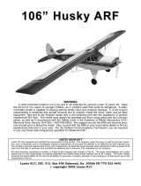
SPECIFICATION
Wingspan : 1,480 mm 58.27 in.
Length : 1,060 mm 41.73 in.
Weight : 2.1 kg 4.62 Lbs.
Radio : 04 channels.
Servo : 04 mini servos (23.6 x 11.6 x 24 mm)
0.92 x 0.45 x 0.94 in.
Motor : EMAX BL2220/07 (2pcs).
Battery: 3 Cells-Li-Poly -11.1V3 3,300 mAh.
Speed control : 35A (2pcs).
Propeller : 10 x 5
Instruction Manual book
Made in Vietnam.

AERO COMMANDER SHRIKE- EP -Item code: BH89 INSTRUCTION MANUAL.
2
This instruction manual is designed to help you build a great flying aeroplane. Please read this
manual thoroughly before starting assembly of your AERO COMMANDER SHRIKE-EP. Use the
parts listing below to identify all parts.
WARNING.
Please be aware that this aeroplane is not a toy and if assembled or used incorrectly it is
capable of causing injury to people or property. WHEN YOU FLY THIS AEROPLANE YOU
ASSUME ALL RISK & RESPONSIBILITY.
If you are inexperienced with basic R/C flight we strongly recommend you contact your R/C supplier
and join your local R/C Model Flying Club. R/C Model Flying Clubs offer a variety of training
procedures designed to help the new pilot on his way to successful R/C flight. They will also be able
to advise on any insurance and safety regulations that may apply.
TOOLS & SUPPLIES NEEDED.
Thick cyanoacrylate glue.
30 minute epoxy.
5 minute epoxy.
Hand or electric drill.
Assorted drill bits.
Modelling knife.
Straight edge ruler.
2mm ball driver.
Phillips head screwdriver.
220 grit sandpaper.
90° square or builder’s triangle.
Wire cutters.
Masking tape & T-pins.
Thread-lock.
Paper towels.
Some more parts.
HARDWARE PACK
COWLING.
Landing gear.....
T
o avoid scratching your new airplane, do not
unwrap the pieces until they are needed for
assembly. Cover your workbench with an old
towel or brown paper , both to protect the
aircraft and to protect the table. Keep a couple
of jars or bowls handy to hold the small parts
after you open the bag.
Please trial fit all the parts. Make sure you have
the correct parts and that they fit and are
aligned properly before gluing! This will assure
proper assembly.
AERO COMMANDER SHRIKE-EP
ARF is hand made from natural materials, every
plane is unique and minor adjustments may
have to be made. However , you should find
the fit superior and assembly simple.
The painted and plastic parts used in this kit
are fuel proof. However, they are not tolerant
of many harsh chemicals including the
following: paint thinner, C/A glue accelerator,
C/A glue debonder and acetone. Do not let
these chemicals come in contact with the
colors on the covering and the plastic parts.
PARTS LISTING.
FUSELAGE ASSEMBLY
(1) Fuselage.
WING ASSEMBLY
(1) Right wing half with pre-installed
aileron.
(1) Left wing half with pre-installed
aileron.
Tail section assembly
(1) Vertical stabilizer with pre-
installed rudder.
(1) Horizontal stabilizer with pre-
installed elevator halves.
SUGGESTION.
NOTE.

3
AERO COMMANDER SHRIKE- EP -Item code: BH89 INSTRUCTION MANUAL.
Caution: this model is not a toy!
If you are a beginner to this type of powered
model, please ask an experienced model flyer
for help and support. If you attempt to operate
the model without knowing what you are doing
you could easily injure yourself or somebody
else. Please keep your safety and well-being
in mind at all times.
Important: before you start construction
Even if you have already built a large number
of RC models please read right through these
instructions and check all the kit components
against the parts list. We have taken great
trouble to keep construction as simple as
possible, without making any compromises
in the area of safety.
Note regarding the film covering
Minor creases or bubbles may develop in the
film covering due to major fluctuations in
weather conditions (temperature, humidity
etc.); in rare cases you may even find a slight
warp in a component. These minor faults are
in the nature of film-covered built-up wooden
structures, and can easily be corrected using
a heat gun, as commonly used for modelling.
Creases: Blow warm air over the area
and rub down with a soft
cloth.
Caution! do not heat the film more than is
absolutely necessary. If the air or the iron is
too hot, the film may melt and holes may be
formed.
This model is highly pre-fabricated and can
be built in a very short time. However, the work
which you have to carry out is important and
must be done carefully . The model will only
be strong and fly well if you complete your
tasks competently - so please work slowly and
accurately.
When self-tapping screws have to be
screwed into wood, apply a little white glue
to prevent them shaking loose: just squirt
white glue into the hole and fit the screw.
+ This is not a toy
+ Be sure that no other flyers are using your
radio frequency.
+The glow plug clip must be securely attached
to the glow plug.
SAFETY PRECAUTION.
+ Do not flip the propeller with your fingers.
+ Keep loose clothing and wires away from
the propeller.
+Do not start the motor if people are near. Do
not stand in line with the side of the propeller.
REPLACEMENT LARGE PARTS
Wing warp: Hold the panel twisted gently
in the opposite direction to
the warp, and apply warm
air to remove the creases
from the covering.
A1
A2
B
B
C
D
E
F
G

AERO COMMANDER SHRIKE- EP -Item code: BH89 INSTRUCTION MANUAL.
4
1) Install the rubber grommets and brass
eyelets onto the aileron servo.
INSTALLING THE AILERON SERVO.
B. Wing panel.
C. Fuselage.
D. Horizontal stabilizer.
E. Vertical stabilizer.
REPLACEMENT SMALL PARTS
F. Aluminium wing dihedral brace.
A1. Right nacelle cover.
A 2. Left nacelle cover.
6.Plastic for bottom fuselage.
3a. Wheels 65mm diameter.
1. Nose and landing Gear w/o Wheels.
3b. Nose wheel 55mm diameter.
5. Spinners.
2. Nose and landing Gear w/o Wheels.
7. Plastic for pushrod.
4. Ply wood pieces for wing panel assembly.
G. Decal sheet.
Bottom side of left wing
1.
3b.
4.
5.
2.
3a.
6.
7.
2x10mm

5
AERO COMMANDER SHRIKE- EP -Item code: BH89 INSTRUCTION MANUAL.
C/A glue.
Aileron
C/A glue.
C/A glue.
C/A glue.
2) Using a modeling knife, remove the cov-
ering at possition show below.
Remove
covering
Secure
4) Drill 1,6mm pilot holes through the block
of wood for each of the four mounting screws
provided with the servo.
3) Using the thread as a guide and using
masking tape, tape the servo lead to the end
of the thread: carefully pull the thread out.
When you have pulled the servo lead out, re-
move the masking tape and the servo lead
from the thread.
5. Instal servo tray with aileron servo into
the wing as same as picture below.
Electric wire
thread

AERO COMMANDER SHRIKE- EP -Item code: BH89 INSTRUCTION MANUAL.
6
INSTALLING THE AILERON
LINKAGES.
Secure.
2x10mm.
1) Using a ruler & pen to draw a straight
line as below picture.
INSTALLING THE AILERON
CONTROL HORN.
Bottom side
Secure
2) Insert aileron control horn to the aileron.
3) Drill two 2mm holes through the aileron
using the control horn as a guide and screw
the control horn in place.
2mm X 20mm.
Drill 2mm
hole
Straitgh line.
Pen.
60mm
M2 lock nut
M 2

7
AERO COMMANDER SHRIKE- EP -Item code: BH89 INSTRUCTION MANUAL.
PARTS REQUIRED
MAIN GEAR INSTALATION.
3 x 12mm
Remove covering
3 x 12mm
Drill 2mm
hole
Secure.
Repeat the procedure for the other
wing half.

AERO COMMANDER SHRIKE- EP -Item code: BH89 INSTRUCTION MANUAL.
8
INSTALLING ELECTRIC MOTOR.
See pictures below:
C/A glue.
C/A glue.
Balsa wood piece
3 x 15mm
Secure.
C/A glue.

9
AERO COMMANDER SHRIKE- EP -Item code: BH89 INSTRUCTION MANUAL.

AERO COMMANDER SHRIKE- EP -Item code: BH89 INSTRUCTION MANUAL.
10
Install the spinner backplate, propeller and
spinner cone. The spinner cone is held in
place using two 3mm x 12mm wood screws.
INSTALLING THE SPINNER.
2 x 10mm
1. Slide the fiberglass cowl over the en-
gine and line up the back edge of the cowl with
the marks you made on the fuselage.
COWLING.
3 x 12mm
Secure

11
AERO COMMANDER SHRIKE- EP -Item code: BH89 INSTRUCTION MANUAL.
Secure.
Top side of the wing .
Top side
Secure.
1. Install the rubber grommets and brass
collets into the elevator servo. Test fit the servo
into the servo tray.
2. Mount the servo to the tray using the
mounting screws provided with your radio sys-
tem.
SERVO INSTALLATION.
ELEVATOR INSTALLATION.
Repeat the procedure for the other
wing half.
Bottom side of the wing .

AERO COMMANDER SHRIKE- EP -Item code: BH89 INSTRUCTION MANUAL.
12
C/A glue.
C/A glue.
1. Draw a center line onto the horizontal
stabilizer. Then slide the horizont al into the
fuselage.
2 Using a modeling knife, cut away the
covering from the fuselage for the stabilizer
and remove it.
Center line
Remove
covering
HORIZONTAL STABILIZER.
See pictures below:
C/A glue.
C/A glue.
C/A glue.
C/A glue.
Top side
Elevator servo
.

13
AERO COMMANDER SHRIKE- EP -Item code: BH89 INSTRUCTION MANUAL.
3. Mark the shape of the vertical on the left
and right sides onto the horizontal stabilizer
using a felt-tip pen
4. Remove the stabilizer. Using the lines
you just drew as a guide, carefully remove the
covering from between them using a modeling
knife.
When cutting through the cover-
ing to remove it, cut with only enough pres-
sure to only cut through the covering it’s
self. Cutting into the balsa structure may
weaken it. This could lead to possible fail-
ure during flight
Bottom side
Mark line
Remove
covering
5. When you are sure that everything is
aligned correctly, mix up a generous amount
of 30 minute epoxy. Apply a thin layer to the
top and bottom of the stabilizer mounting area
and to the stabilizer mounting platform sides
in the fuselage. Slide the stabilizer in place and
re-align. Double check all of your measure-
ments one more time before the epoxy cures.
Remove any excess epoxy using a paper
towel and rubbing alcohol and hold the stabi-
lizer in place with T-pins or masking tape.
6. After the epoxy has fully cured, remove
the masking tape or T-pins used to hold the
stabilizer in place and carefully inspect the
glue joints. Use more epoxy to fill in any
gaps that were not filled previously and
clean up the excess using a paper towel and
rubbing alcohol.
Epoxy glue
C/A glue
Check to mark sure the wing and stabi-
lizer are paralell. If they are not, lightly sand
the opening in the fuselage for the stabilizer
until the stabilizer is paralell to the wing.

AERO COMMANDER SHRIKE- EP -Item code: BH89 INSTRUCTION MANUAL.
14
Elevator control horn install as same as the
way of aileron control horn. Please see pic-
tures below.
Elevator and rudder pushrod install as same
as the way of aileron pushrod.
M2
M2 lock nut.
Secure.
Elevator
pushrod
.
ELEVATOR PUSHROD INSTALLATION.
Drill a hole 2mm
diameter.
ELEVATOR CONTROL HORN INSTALLA-
TION.
C/A glue
C/A glue
2*20mm.

15
AERO COMMANDER SHRIKE- EP -Item code: BH89 INSTRUCTION MANUAL.
Secure
Secure
Elevator pushrod.
Secure
Rudder servo install as same as method of
elevator servo. See picture below:
Elevator pushrod
.
Rudder servo
.
C/A glue.
C/A glue.
VERTICAL INSTALLATION.

AERO COMMANDER SHRIKE- EP -Item code: BH89 INSTRUCTION MANUAL.
16
2. Mark the shape of the vertical on the left
and right side of the rudder on to the horizon-
tal stabilizer using a felt-tip pen.
1. Put the rudder into the fuselage as same
as picture below.
3. Now, remove the rudder and using a
modeling knife, carefully cut just inside the
marked lines and remove the film of the rud-
der. Just as you did with the horizontal stabi-
lizer, make sure you only press hard enough
to cut the film, not the balsa rudder.
Also carefully remove the covering from
below the lines as you drew as same picture
below.
Mark line
90º
Vertical
Stabilizer.
Horizontal
Stabilizer.
Remove
covering
5) When you are sure that everything is a
aligned correctly, mix up a generous amount
of 30 minute epoxy. Apply a thin layer to the
slot in the mounting platform and to the verti-
cal stabilizer mounting area. Apply epoxy to
the lower rudder hinge. Set the stabilizer in
place and re-align. Double check all of your
measurements once more before the epoxy
cures. Remove any excess epoxy using a
paper towel and rubbing alcohol and hold the
stabilizer in place with T-pins or masking tape.
Allow the epoxy to fully cure before proceed-
ing.
4. Put the vertical stabilizer back in
place. Using a triangle, check to ensure
that the vertical stabilizer is aligned 90 de-
gree to the horizontal stabilizer.
Epoxy glue

17
AERO COMMANDER SHRIKE- EP -Item code: BH89 INSTRUCTION MANUAL.
Epoxy glue
Epoxy glue
C/A glue.
C/A glue.
C/A glue.

AERO COMMANDER SHRIKE- EP -Item code: BH89 INSTRUCTION MANUAL.
18
C/A glue.
C/A glue.
Epoxy glue

19
AERO COMMANDER SHRIKE- EP -Item code: BH89 INSTRUCTION MANUAL.
INSTALLING THE NOSE GEAR.
Micro control
connector.
Secure
To p
Attach the pushrod wire to the steering
arm.
Cut

AERO COMMANDER SHRIKE- EP -Item code: BH89 INSTRUCTION MANUAL.
20
C/A glue.
1. Plug the servo leads and the switch
lead into the receiver. You may want to plug
an aileron extension into the receiver to make
plugging in the aileron servo lead easier
when you are installing the wing . Plug the
battery pack lead into the switch.
2. Wrap the receiver and battery pack in
the protective foam to protect them from vi-
bration. Use a rubber band or masking tape to
hold the foam in place.
Do not permanently secure the receiver
and battery until after balancing the model.
3. Position the battery pack and receiver
behind the fuel tank. Use two tie wraps to hold
the battery and receiver securely in place as
pictures below
4. Using a 2mm drill bit, drill a hole through
the side of the fuselage, near the receiver, for
the antenna to exit.
Secure
Nose gear pushrod.
Cut
INSTALLING THE RECEIVER AND BATTERY.
Tie wrap.
Secure
/