Page is loading ...

ROUTER TABLE
MODEL H3114
INSTRUCTION MANUAL
COPYRIGHT © DECEMBER 2002 BY GRIZZLY INDUSTRIAL, INC
WARNING: NO PORTION OF THIS MANUAL MAY BE REPRODUCED IN ANY SHAPE
OR FORM WITHOUT THE WRITTEN APPROVAL OF GRIZZLY INDUSTRIAL, INC.
PRINTED IN CHINA
ONLINE MANUAL DISCLAIMER
THE INFORMATION IN THIS MANUAL REPRESENTS THE CONFIGURATION OF THE MACHINE AS IT IS CURRENTLY BEING SHIPPED. THE
MACHINE CONFIGURATION CAN CHANGE AS PRODUCT IMPROVEMENTS ARE INCORPORATED. IF YOU OWN AN EARLIER VERSION OF
THE MACHINE, THIS MANUAL MAY NOT EXACTLY DEPICT YOUR MACHINE . CONTACT CUSTOMER SERVICE IF YOU HAVE ANY QUESTIONS
ABOUT DIFFERENCES. PREVIOUS VERSIONS ARE NOT AVAILABLE ONLINE.

WARNING
Some dust created by power sanding, sawing, grinding,
drilling, and other construction activities contains chemi-
cals known to the State of California to cause cancer, birth
defects or other reproductive harm. Some examples of
these chemicals are:
• Lead from lead-based paints.
• Crystalline silica from bricks, cement, and other
masonry products.
• Arsenic and chromium from chemically treated
lumber.
Your risk from these exposures varies, depending on how
often you do this type of work. To reduce your exposure to
these chemicals: work in a well ventilated area, and work
with approved safety equipment, such as those dust
masks that are specially designed to filter out microscopic
particles.

TABLE OF CONTENTS
PAGE
1. SAFETY ......................................................................................................................................................2
SAFETY INSTRUCTIONS FOR POWER TOOLS............................................................................2-3
ADDITIONAL SAFETY INSTRUCTIONS FOR ROUTER TABLES ....................................................4
2. INTRODUCTION ........................................................................................................................................5
COMMENTARY....................................................................................................................................5
3. CIRCUIT REQUIREMENTS ........................................................................................................................6
GENERAL ............................................................................................................................................6
ELECTRICAL ......................................................................................................................................6
4. SET UP........................................................................................................................................................7
MAIN FEATURES ................................................................................................................................7
ASSEMBLY ....................................................................................................................................8-13
OPERATION ................................................................................................................................14-16
5. REFERENCE INFO ..................................................................................................................................17
PARTS BREAKDOWNS AND LIST ..................................................................................................................18-19
WARRANTY AND RETURNS ..........................................................................................................................22-24

-2- H3114 Router Table
SECTION 1: SAFETY
For Your Own Safety Read Instruction
Manual Before Operating This Equipment
Indicates an imminently hazardous situation which, if not avoided,
WILL result in death or serious injury.
Indicates a potentially hazardous situation which, if not avoided,
COULD result in death or serious injury.
Indicates a potentially hazardous situation which, if not avoided,
MAY result in minor or moderate injury, or MAY cause property
damage.
This symbol is used to alert the user to useful information about
proper operation of the equipment.
The purpose of safety symbols is to attract your attention to possible hazardous conditions. This
manual uses a series of symbols and signal words which are intended to convey the level of
importance of the safety messages. The progression of symbols is described below. Remember
that safety messages by themselves do not eliminate danger and are not a substitute for proper
accident prevention measures.
NOTICE
Safety Instructions For Power Tools
5. KEEP CHILDREN AND VISITORS
AWAY. All children and visitors should be
kept at a safe distance from work area.
6. MAKE WORKSHOP CHILD PROOF with
padlocks, master switches, or by removing
starter keys.
7. DO NOT FORCE TOOL. It will do the job
better and safer at the rate for which it was
designed.
8. USE RIGHT TOOL. Do not force tool or
attachment to do a job for which it was not
designed.
1. KEEP GUARDS IN PLACE and in working
order.
2. REMOVE ADJUSTING KEYS AND
WRENCHES. Form habit of checking to
see that keys and adjusting wrenches are
removed from tool before turning on.
3. KEEP WORK AREA CLEAN. Cluttered
areas and benches invite accidents.
4. DO NOT USE IN DANGEROUS ENVI-
RONMENT. Do not use power tools in
damp or wet locations, or where any flam-
mable or noxious fumes may exist. Keep
work area well lighted.

H3114 Router Table -3-
9. USE PROPER EXTENSION CORD. Make
sure your extension cord is in good condi-
tion. Conductor size must be in accor-
dance with the chart below. The amperage
rating is listed on the motor or tool name-
plate. An undersized cord will cause a drop
in line voltage resulting in loss of power
and overheating. Your extension cord
must also contain a ground wire and plug
pin. Always repair or replace damaged
extension cords.
Minimum Gauge for Extension Cords
10. WEAR PROPER APPAREL. Do not wear
loose clothing, gloves, neckties, rings,
bracelets, or other jewelry which may get
caught in moving parts. Non-slip footwear
is recommended. Wear protective hair
covering to contain long hair.
11. ALWAYS USE ANSI-APPROVED SAFE-
TY GLASSES. Also use face or dust mask
if cutting operation is dusty. Everyday eye-
glasses only have impact resistant lenses,
they are NOT safety glasses.
12. SECURE WORK. Use clamps or a vise to
hold work when practical. It is safer than
using your hand and frees both hands to
operate tool.
13. NEVER OVERREACH. Keep proper foot-
ing and balance at all times.
LENGTH
AMP RATING 25ft 50ft 100ft
0-6 18 16 16
7-10 18 16 14
11-12 16 16 14
13-16 14 12 12
17-20 12 12 10
21-30 10 10 No
Safety Instructions For Power Tools
14. MAINTAIN TOOLS WITH CARE. Keep
tools sharp and clean for best and safest
performance. Follow instructions for lubri-
cating and changing accessories.
15. DISCONNECT TOOLS before servicing
and changing accessories, such as blades,
bits, cutters, and any other item.
16. REDUCE THE RISK OF UNINTENTIONAL
STARTING. Make sure switch is in off posi-
tion before plugging in. Also, the magnetic
switch on this machine may start if the
switch gets bumped hard enough.
17. USE RECOMMENDED ACCESSORIES.
Consult the owner’s manual for recom-
mended accessories. The use of improper
accessories may cause risk of injury.
18. CHECK DAMAGED PARTS. Before further
use of the tool, a guard or other part that is
damaged should be carefully checked to
determine that it will operate properly and
perform its intended function. Check for
alignment of moving parts, binding of mov-
ing parts, breakage of parts, mounting, and
any other conditions that may affect its
operation. A guard or other part that is dam-
aged must be properly repaired or
replaced.
19. NEVER LEAVE TOOL RUNNING UNAT-
TENDED. TURN POWER OFF. Do not
leave tool until it comes to a complete stop.
20. NEVER USE UNDER THE INFLUENCE of
alcohol or drugs, or when tired.
21. IF AT ANY TIME YOU ARE EXPERIENC-
ING DIFFICULTIES performing the intend-
ed operation, stop using the machine! Then
contact our service department or ask a
qualified expert how the operation should
be performed.

-4- H3114 Router Table
1. HAND POSITIONING. Never pass your
hands directly over, or in front of the cutter. As
one hand approaches cutter, move it in an arc
motion away from the cutter to the outfeed
side and reposition that hand beyond the cut-
ter.
2. STOCK LENGTH. Do not shape stock short-
er than 12 inches without special fixtures or
jigs. Where practical, shape longer stock and
cut to size.
3. BLIND CUT WHENEVER POSSIBLE. This
keeps the cutters on the underside of the
workpiece and provides a distance guard for
the operator.
4. TEST ROTATION. Always rotate the spindle
by hand, with the machine unplugged, to test
any new setup to ensure proper cutter clear-
ance before starting the machine.
5. KEEP ANY UNUSED PORTION OF THE
CUTTER BELOW THE TABLE SURFACE.
6. DEPTH OF CUT. Never remove too much
material in one pass. Several light passes are
safer and give a cleaner finish.
7. SAFETY DEVICES. The use of push sticks
as safety devices in some applications is
smart; in others it can be quite dangerous. If
the push stick comes in contact with the cut-
ter on the end grain, it can fly out of your hand
like a bullet—potentially causing serious
injury.
We recommend using some type of fixture,
jig, or hold-down device as a safer alterna-
tive. Use a guard or other type of protective
device at all times.
8. ALWAYS FEED AGAINST THE ROTA-
TION OF THE CUTTER.
9. DO NOT REMOVE THE RETRACTABLE
GUARD ON THE FENCE.
10. IF AT ANYTIME YOU ARE EXPERIENC-
ING DIFFICULTIES PERFORMING THE
INTENDED OPERATION, STOP USING
THE ROUTER TABLE! Then contact our
service department or ask a qualified expert
how the operation should be performed.
11. BE AWARE THAT CERTAIN WOODS
MAY CAUSE AN ALLERGIC REACTION
in people and animals, especially when
exposed to fine dust. Make sure you know
what type of wood dust you will be exposed
to, the possibility of a allergic reaction and
always wear an approved respirator.
12. NEVER REACH BEHIND THE SPINNING
CUTTER.
13. READ AND UNDERSTAND THE
INSTRUCTION MANUAL SUPPLIED
WITH THE ROUTER INSTALLED IN THIS
TABLE
14. DO NOT REACH UNDER THE ROUTER
TABLE WHILE THE ROUTER IS
PLUGGED IN OR RUNNING.
Additional Safety Instructions For Router Tables

H3114 Router Table -5-
SECTION 2: INTRODUCTION
We are proud to offer the Grizzly Model H3114
Router Table. The Model H3114 is part of a grow-
ing Grizzly family of fine woodworking machinery.
When used according to the guidelines set forth
in this manual, you can expect years of trouble-
free, enjoyable operation and proof of Grizzly’s
commitment to customer satisfaction.
Features include:
• Over 440 square inches of work surface
• Master power switch controls a router and
another accessory such as a shop vac
• Universal clamping system allows the mount-
ing of most brands of routers
• Heavy-duty fence system with dust port
• Pocket jointing fence allows router table to
function as a jointer
•Miter gauge
• Various table inserts
•Convenient fence scales allow for precise
adjustment
• Retractable safety guard
• Heavy-duty cast aluminum table
Grizzly is also pleased to provide this manual
with the Model H3114. It was written to guide you
through assembly, review safety considerations,
and cover general operating procedures. If you
have any comments regarding this manual,
please write to us at the address below:
Grizzly Industrial, Inc.
C
/O Technical Documentation
P.O. Box 2069
Bellingham, WA 98227-2069
Commentary
Most importantly, we stand behind our machines.
If you have any service questions or parts
requests, please call or write us at the location
listed below:
Grizzly Industrial, Inc.
1203 Lycoming Mall Circle
Muncy, PA 17756
Phone: (570) 546-9663
Fax: (800) 438-5901
E-Mail: [email protected]
Web Site: http://www.grizzly.com
The specifications, drawings, and photographs
illustrated in this manual represent the Model
H3114 as supplied when the manual was pre-
pared. However, owing to Grizzly’s policy of con-
tinuous improvement, changes may be made at
any time with no obligation on the part of Grizzly.
Current Grizzly machine manuals can be viewed
and printed at: www.grizzly.com.
Lack of familiarity with
this manual could
cause serious person-
al injury. Become
familiar with the con-
tents of this manual,
including all the safety
warnings.

-6- H3114 Router Table
SECTION 3: CIRCUIT REQUIREMENTS
General
Electrical
The power switch (Page 7, Figure 2) on the
Model H3114 is designed to work with most
routers and other electrical accessories. The
power switch provides the convenience of switch-
ing power to the router and accessories at the
front of the router table instead of having to reach
under the table and locate multiple switches. The
power switch also allows multiple devices such as
lights or vacuums to be powered on when the
router is powered on.
The Model H3114 power switch is designed to
accept 2-prong DOUBLE INSULATED plugs or 3-
prong grounding type plugs. The power switch
plugs into a wall outlet that is properly grounded
as shown in Figure 1.
If the machine is wired incorrectly a fire
could result. Make sure your wiring, recep-
tacle, plug, and circuit breaker can handle
the current draw of the machine. If you are
not sure that your electrical circuit can han-
dle the current draw, get a qualified electri-
cian to test your electrical system and do
any required upgrades. Do not attempt to
modify an existing circuit by only replacing
the circuit breaker with one rated for a high-
er amperage draw than the wiring, recepta-
cle, and plug are rated for.
Figure 1. Power switch 3-prong plug and
grounding style outlet.
Grounding Prong
Current Carrying Prongs
Grounded Outlet

H3114 Router Table -7-
Main Features
SECTION 4: SET UP
Set up and operation instructions will be easier to understand if you become familiar with the location and
names of the basic features shown in Figure 2.
Figure 2. Machine features.
Extension Table
Power Switch
Note–Only 1 of the 5 table inserts are shown.
Leg
Main Table
Miter Gauge
Main Fence
Dust Port
Table Insert
Retractable
Guard
Pocket
Jointing
Fence

-8- H3114 Router Table
Assembly
Figure 3. Aligning an extension table
with the main table.
To attach the extension tables and legs to the
main table:
1. Place the main table upside down on a work-
bench.
2. Align the extension tables mounting holes
with the mounting holes on the edge of the
main table (Figure 3). Note—DO NOT
secure the extension tables with screws at
this time.
Loose hair and clothing
could get caught in
machinery causing seri-
ous personal injury.
Keep loose clothing
rolled up and long hair
tied up and away from
machinery.
Projectiles thrown from
the machine could cause
serious eye injury. Wear
safety glasses during
assembly.
Disconnect power to the
machine during the
entire assembly process.
Failure to do this may
result in serious person-
al injury.
!
Sharp edges on metal
parts may cause person-
al injury. Examine the
edges of all metal parts
before handling.
Main Table
Extension Table

H3114 Router Table -9-
To check the flushness of the table:
1. Place a straightedge across both extension
tables and the main table. The straightedge
should sit flush on all three surfaces as
shown in Figure 6.
2. If either extension table is not flush with the
main table, loosen the mounting screws and
adjust the assembly until both extension
tables and the main table are flush with one
another.
3. Retighten the mounting screws.
4. Double check the the flushness of the work-
ing surface with the straightedge.
Figure 6. Using a straightedge to ensure the
working surfaces are flush.
Figure 4. Aligning a leg with the main table.
Figure 5. Securing a leg to the main table.
3. Align one of the legs with the mounting holes
on the inside edge of the main table as
shown in Figure 4.
4. Secure the leg and extension table to the
main table with the supplied #10-32 x
3
⁄4"
truss head phillips screws and the #10-32
keps nuts as shown in Figure 5.
5. Repeat Steps 3 & 4 for the remaining three
legs.

-10- H3114 Router Table
Figure 7. Router positioned correctly for
"Method 1" installation.
3. Rotate the router until the main table mount-
ing holes align with the mounting holes in the
router base. Note—Orient the router so the
adjustment controls are easy to reach.
4. With the three screws removed in Step 1,
secure the router to the underside of the
main table.
Method 2
1. Remove the base plate from the router base.
Note–The bottom face of the router base
must form a continuous ring with no gaps. If
the router base does not have this design,
DO NOT remove the base plate.
2. Turn the router table upside down.
3. Insert the supplied M5-0.8 x 45 carriage bolts
through the four large mounting holes in the
top of the main table.
4. Slide the four clamps over the ends of the
carriage bolts with the tabs facing the under-
side of the main table as shown in Figure 8.
5. Begin threading the M5-0.8 keps nuts onto
the ends of the M5-0.8 x 45 carriage bolts.
6. Rotate the clamps out of the circular recess
and position the router base against the cir-
cular recessed area.
Figure 8. Clamps for securing “Method 2” style
routers to the main table.
To mount the router to the table:
The base plate mounting holes on some brands
of routers may align with the router mounting
holes on the main table. If the holes line up, con-
tinue with Method 1. If the holes do not line up,
skip ahead to Method 2.
Method 1
1. Remove the base plate from the router base
by removing the three base plate screws.
Note—The router base plate is usually a cir-
cular black plastic plate that is screwed to the
router base.
2. Turn the router upside down and hold the
router base against the circular recess in the
underside of the main table as shown in
Figure 7.
Circular Recess
Clamps

H3114 Router Table -11-
Figure 11. Correct spring placement.
Figure 12. Correctly installed guard.
Figure 10. Correctly clamped router.
2. Insert the retractable guard into the fence
and secure the guard with the supplied M4 x
12 tap screw and the M5 flat washer (Figure
12). The bit guard should move freely with no
binding on the fence. If binding occurs, light-
ly sand or file the contact areas.
To assemble the fence:
1. Attach the spring to the retractable guard as
shown in Figure 11.
7. Hold the router and rotate the clamps over
the router base as shown in
Figure 9
.
8. Tighten the M5-0.8 keps nuts enough to pre-
vent the router from moving, but DO NOT
fully tighten them at this time.
9. Turn the router table top-side up.
10. Loosen the M5-0.8 keps nuts several turns
and reposition the router until the router spin-
dle is centered in the round table cut-out
when viewed from above.
11. Tighten the M5-0.8 keps nuts (
Figure 10
).
Figure 9. Rotating a clamp over
the router base.
Spring
Retractable Guard
Clamp Position

-12- H3114 Router Table
Figure 13. Installing the pocket jointing fence.
Figure 14. Securing the fence to the main table.
3. Slide the pocket jointing fence into the slot in
the face of the main fence as shown in
Figure 13.
4. Secure the pocket jointing fence to the main
fence with the supplied M8-1.0 x 20 hex bolt
and the M8-1.0 threaded knob.
5. Place the fence assembly on the main table.
6. Align the slots on the fence assembly over
the slots on the table surface.
7. Secure the fence assembly to the table with
the supplied M8-1.0 x 40 hex bolts and the
M8-1.0 threaded knobs as shown in Figure
14.
Figure 15. Securing the power switch
to the main table.
2. Flip the table assembly top-side up
.
To attach the power switch to the main table:
1. Secure the power switch to the main table
with the supplied #10-32 x
3
⁄4" truss head
phillips screws and the #10-32 keps nuts as
shown in Figure 15. Note—The power switch
mounting bracket should be on the inside of
the main table edge.

H3114 Router Table -13-
Figure 16. Router table mounting holes.
Figure 17. Miter gauge components.
Figure 18. Assembled miter gauge.
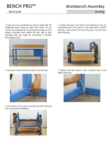
To secure the router table to a workbench:
The bottom of each leg has two holes (
Figure 16
)
used for mounting the router table to the work-
bench. Secure the router table to the workbench
with wood screws and washers.
To assemble the miter gauge (Figure 17 & 18):
1. Attach the miter body to the miter bar with the
supplied M4 x 12 tap screw.
2. Place the M8 flat washer over the M8-1.0 x
12 knob bolt.
3. Slide the M8-1.0 x 12 knob bolt through the
miter body slot and thread it into the miter
bar.
Tap Screw
Miter Body
Knob Bolt
Miter Bar
Flat Washer

-14- H3114 Router Table
5. Loosen the threaded knobs that secure the
main fence.
6. Place a straightedge across the entire face of
the pocket jointing fence and adjust the main
fence until the outside diameter of the router
bit just touches the straightedge (Figure 20).
Figure 19. Proper setup for jointing an edge.
Figure 20. Use a straightedge to properly adjust
the main fence.
Routing operations on your Model H3114 are
grouped into three main techniques:
• Jointing an edge (Page 14)
•Groove cutting (Page 15)
•Profile cutting with pilot bits (Page 16)
Jointing an edge:
Jointing the edge of a board involves using a
straight cutting router bit to remove wood from the
edge face of a board. The result is a perfectly flat
and square edge used as the glue edge when
gluing multiple boards together to form a larger
panel.
1. Secure a straight cutting router bit into your
router according to the router manufacturer’s
instructions.
2. Snap one of the table inserts into the
recessed hole on the table. Use the insert
with the smallest hole that still allows the bit
free rotation.
3. Raise the bit to a height equal to that of the
thickness of your board.
4. Loosen the threaded knob on the pocket
jointing fence and slide the pocket jointing
fence from the main fence to the desired
depth of cut (Figure 19). Tighten the thread-
ed knob when adjusted correctly. Note–The
face of the pocket jointing fence must be par-
allel to the main fence face before performing
any routing operations.
Operation
7. Tighten the main fence threaded knobs.
8. Double check that the router is secured to the
table. If it is, the router table is ready for use.
Pocket Jointing
Fence
Router Bit
Main Fence
Threaded Knob
Depth Of Cut
Just
Touches
Here
Straightedge Contact
Across Entire Pocket
Jointing Fence Face
Loose hair and clothing
could get caught in
machinery causing seri-
ous personal injury.
Keep loose clothing
rolled up and long hair
tied up and away from
machinery.
Projectiles thrown from
the machine could cause
serious eye injury. Wear
safety glasses during
assembly.

H3114 Router Table -15-
6. Tighten the main fence threaded knobs.
7. Double check that the router is secured to the
table. If it is, the router table is ready for use.
Groove cutting:
Beading is commonly defined as cutting a groove
or bead in the face of a board.
1. Mount a router bit into your router according
to the router manufacturer’s instructions.
2. Snap one of the table inserts into the
recessed hole on the table. Use the insert
with the smallest hole that still allows the bit
free rotation.
3. Raise the bit to the desired height.
4. Loosen the threaded knobs that secure the
main fence.
5. Adjust the main fence until the center of the
V-groove bit is the desired distance away as
shown in Figure 21 & 22.
Figure 21. Groove cutting setup.
(Top View)
Figure 22. Groove cutting setup.
(Side View)
Distance From
Edge Of Board
To Center Of
V-Groove
Distance From
Edge Of Board
To Center Of
V-Groove

-16- H3114 Router Table
7. Tighten the main fence threaded knobs.
8. Double check that the router is secured to the
table. If it is, the router table is ready for use.
Profile cutting with pilot bits:
Router bits with ball bearings are called pilot bits.
The ball bearing is used to control the depth of cut
into the edge face of a board. A good example
would be a chamfer cut. The bearing rides along
the uncut edge of the board while the cutter
removes the wood.
1. Mount a router bit into your router according
to the router manufacturer’s instructions.
2. Snap one of the table inserts into the
recessed hole on the table. Use the insert
with the smallest hole that still allows the bit
free rotation.
3. Raise the bit to the desired height.
4. Loosen the threaded knobs that secure the
main fence.
5. Adjust the fence back away from the bit only
enough to allow the bearing to control the
depth of cut as shown in Figure 23 & 24.
6. Adjust the fence as close as possible to the
bearing. The fence will serve as a back-up
support, reducing the chance of an accident.
Figure 23. Proper setup for profile cutting.
(Top View)
Figure 24. Proper setup for profile cutting.
(Side View)
Router Bit
Ball Bearing
Router Bit
Ball Bearing

H3114 Router Table -17-
SECTION 5: REFERENCE INFO
If you need parts or help in assembling your
machine, or if you need operational information,
call the Grizzly Service Department. Trained ser-
vice technicians will be glad to help you.
If you have any comments regarding this manual,
please write to Grizzly at the address below:
Grizzly Industrial, Inc.
C
/O Technical Documentation
P.O. Box 2069
Bellingham, WA 98227-2069
Important safety measures that are essential to
the operation of this machine have been
explained in Section 1: Safety. While most safety
measures are generally universal, Grizzly
reminds you that each workshop is different and
safety rules should be considered as they apply to
your specific situation.
We recommend you keep a copy of our current
catalog for complete information regarding
Grizzly's warranty and return policy. If you need
additional technical information relating to this
machine, or if you need general assistance or
replacement parts, please contact the Service
Department at the location listed below.
Grizzly Industrial, Inc.
1203 Lycoming Circle
Muncy, PA 17756
Phone: (570) 546-9663
Fax: (800) 438-5901
E-Mail: [email protected]
Web Site: http://www.grizzly.com.
Additional information sources are necessary to
realize the full potential of this machine. Trade
journals, woodworking magazines, and your local
library are good places to start.

-18- H3114 Router Table
1
2
3
5
8
10
11
12
13
15
16
17
18
20
21
22
19
23
24
8
25
26
27
28
PARTS BREAKDOWN AND LIST
/