Page is loading ...

Ampli er
Audio Mixer
Infrared Microphone Receiver
™
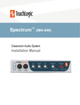
MAXIMTM III
CLASSROOM AUDIO SYSTEM
INSTALLER AND OPERATIONS MANUAL
P/N UMM-500

introduction
Maxim III
thank you
Congratulations on the purchase of your new TeachLogic system. You can be
assured that this ullls all specications and was produced to very high quality
control standards. TeachLogic incorporates the latest state of the art technology,
employs the most advanced manufacturing methodology and uses only premium
quality components to assure many years of reliable performance. We appreciate
your condence by your selection of our product. It is TeachLogic’s intent to
uphold that condence by providing factory assistance and dealer support.
We hope you will take the time to review this manual to familiarize yourself with
the product operation and features. This manual will help you learn to use and
gain the maximum benet of the system.
TeachLogic, LLC
Longmont, Colorado, USA
teachlogic.com

safety instructions
Read Instructions
All safety and operation instructions should be read
before operating this TeachLogic product.
Retain Instructions
Safety and operating instructions should be kept for
future reference.
Water & Moisture
This product should not be operated near water.
Heat Environment
Do not subject this product to excessive heat conditions.
Power Source
This product must be connected to an AC power source
per the voltage input specied and marked on the
power supply.
Power Cord Caution
Power cable should be routed clear of foot trac and
supported clear of kinking or abrasion.
Object Protection
Locate the operating unit so it will not be subjected to
falling objects or water entry.
Internal Service
User should not attempt to service this product. All
internal service must be accomplished by a qualied
technician.
Electric Shock
Do not adapt or modify the AC power plug thus lifting
the earth ground connection.
Recycle—Do not dispose re-
chargeable batteries in trash.
Actually it is unlawful to do so
in CA, NY & ME.
Contact: Earth911.com
1-800-CLEANUP
Save our resources and don’t
contaminate.
Go Green
caution
certifications
TeachLogic systems are
manufactured using lead-
free processes and are free
of materials harmful to the
environment. They conform
to the most stringent new
European guidelines for
consumer products (RoHS).

4
Maxim III
system info
Date of Purchase:
Model Number:
Serial Number:
Notes:
contact
If you should encounter
some unresolved issue,
please contact the
TeachLogic customer
service department for
further assistance.
1•760•631•7800
support@teachlogic.com
teachlogic.com
5-year limited warranty
For full warranty details refer to:
www.teachlogic.com/warranty

table of contents
System Overview ....................................................
System Diagram ......................................................
Installation
Installation Planning...............................................
Installation of Ceiling Sensor ...............................
Installation of Speakers .........................................
Integration
Page Mute/Pass Through Integration ..............
Fire Alarm Input .......................................................
RS-232 Feature .................................................
Security Alert Feature ............................................
Conguration
Intial Setup ...............................................................
Trouble Shooting ....................................................
System Specications ............................................
1
3
5
5
6
7
9
9
10
11
12
15
15
16
17

system overview
1
Maxim III
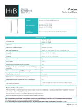
Make note of the components planned for installation and setup. A complete Sound
Field system will have the components shown below. The quantity and type of
components will vary based on your order. Please check your invoice, packing slip, or
contact us with any questions about what components you should have.
1. Speakers - ceiling or wall mount
2. Ceiling Sensor + 50' sensor cable (RCA)
3. Wireless Microphones (IRT-60 & IRH35)
4. Microphone battery charger (BRC-60 shown)
5. Maxim III Receiver/Ampli er
5
4
3
2
1
Sound Field system components

2
front of IMA-520 receiver/amplifier
back of IMA-520 receiver/amplifier
Power on/o
CH A Microphone Volume Control
CH B Microphone Volume Control
DVD Volume Control
Computer Volume Control
Speaker Output
Fire Alarm Input- contact closure
Page Input
Page Sensitivity control
Page impedence selector
ALS gain control
ALS Output (3.5mm)
Five band digital equalizer ±12 dB
RS-232 (Tx,Gnd,Rx) 3-pin
Aux Volume Control
MP3 Volume Control
MP3 Input (3.5mm)
Lesson Capture Volume Control
Lesson Capture Output (3.5mm)
Security Alert - contact closure
Aux-Mic Input Selector
Aux-Mic Input (3.5mm)
Computer Input (3.5mm)
Computer Anti hum ON/OFF
DVD dual Mono Inputs (RCA)
Two IR Mic Sensor Inputs (RCA)
5 Volt USB output for BRC-60
Power Input: 19 VDC 3.4A
1
2
3
4
5
6
7
8
9
10
10
1 1
12
13
14
15
16
17
18
1
2
3
4
5
6
7
8
9
6 7 8 9 1054321
6 7 8 9 1054321 11 12 13 14 15 16 17 18

note
3
Maxim III
owner’s manual
owner’s manual
system diagram

4
owner’s manual
owner’s manual

Maxim III
1. Amplifer/Receiver: Choose location the based on accessibility requirements
and wiring constraints for power, speakers, and audio devices.
2. Ceiling Sensor: Centrally locate on ceiling; maintain line of sight; keep away
from direct light and electrical interference.
3. Speakers: Mark location for wall mount vs. ceiling mount, and conrm wiring
run to the amplier. Ensure speakers evenly cover the listening area.
4. Systems Integration: Conrm location of audio devices, page, re, and/or
security alert systems to the amplier and note how wiring will run.
5. Microphones/Charger: Conrm microphone charging location for daily use/
charging.
installation
2
1
3 3
33
3
3 3
3
4
4
5
5
v
installation planning

6
product description
installation of ICS-55 ceiling sensor
The ideal location for the ceiling sensor is in the center of the room's ceiling. The ideal installation
is ush mounted on a white, reective ceiling like the acoustic drop-down style. This will ensure
360º coverage and will minimize the transmission distance for more reliable performance.
ICS-55
ICS-55
Green light indicates that
the sensor is receiving
power from the receiver.
power “on” LED
v
FINAL STEP: Route sensor's cable to desired amplier location and plug into one of the
two sensor inputs

installation
4
Maxim III
7
installation of speakers
SP-628 ceiling speakers
The IMA-520 (and IMA-524) has two channels of amplied audio, rated for a minimum 4-ohm
speaker load. There are two blue Phoenix style speaker connectors on the back panel, each
providing two pairs of speaker terminals. The top connector provides connection to both
channels as does the bottom connector. Each is wired in parallel to the other as shown
below. These are the acceptable wiring methods.
7

• Ensure amplier is in nal location
• Ensure speaker and sensor cables are neatly routed
• Cut the speaker wire to the appropriate length
• Strip about 3/8” o the end of each speaker wire.
• Twist the wire and if you have a soldering iron, tin the wire ends
• Unplug the phoenix connector, insert (+) wire (with printed writing) into either outside (+)
terminal. Plug the other (-) wire into center (-).
• Tighten set screws.
• Repeat for other pair and insert plug rmly into speaker receptacle
• Plug amplier power supply into AC outlet 7
Four speakers
1. Determine the mounting surface and
location based on the seating area
2. Ordinary installation is to locate the
speakers on each side wall. The rst set
should be in line with the front row of
listeners
3. Mount the speakers 6–7 ft above the
oor
4. Install the mounting brackets in the
vertical (up/down) orientation
5. Mount brackets using the appropriate
hardware
6. Insert speaker with the tweeter in
upper position
7. Secure speaker in bracket with the
hand fasteners
8. Orient each speaker toward the center
of that half of the listening area
9. Strip speaker cable ends ½” and
connect to speaker
10. Observe speaker polarity: Connect (+)
wire (with printed writing) to (+) terminal
and (-) wire (unprinted & textured) to
the (-) terminal
11. Route speaker cable to the receiver/
amplier in a safe, least visible, tidy
manner
final connection of the system
1. Determine the listening area.
2. Divide listening area into quadrants
3. Locate and identify the center most tile
in each quadrant
4. Lay ceiling tile face down on clean at
surface
5. Lay tile bridge on ceiling tile and center it
6. Trace and cut the large hole
7. Strip the speaker cable ends, approx. ½"
8. Route speaker wire from speaker
opening to amplier
9. Reinstall ceiling tile with tile bridge in
place above the hole
10. Pull speaker cable back down through
speaker hole
11. With a pointed tool or paper clip, lift up
and remove speaker grille
12. Connect speaker cable to speaker
terminals
13. Observe speaker polarity, connect wires
to (+) and (-) terminals respectively
14. With the mounting clamps folded back,
position speaker into speaker hole
15. With a #2 Phillips screwdriver, tighten
the mounting clamps
16. Reinstall speaker grille and remove any
soil or ngerprints
17. Repeat these steps for other speakers
SP-2000 wall mount speakers
SP-628 ceiling speakers
8

transmitter
integration
page mute/page pass through
9
Maxim III
Eective for shipments after 4/1/19 of new units; serial numbers beginning with A19
and later (letter or number is A, B, C… and number is 19, 20, …). For older units see
notes at the end of this section.
New units: A paging system may be connected to the Maxim III. The panel labeling is
based on a 25-volt paging input signal.
The Page Input impedance switch has three labeled positions (based on power draw
at 25V):
• 0.1W DRAW
• 1.0W DRAW
• MUTE OFF
MUTE OFF disconnects the page input from the Maxim III. The other two settings select
transformer taps inside the Maxim III for the speakers connected to the top left and
lower right connections. These two connections are labeled A1 and A2 in Diagram A
below.
ADVISORY: These two speaker terminals are internally wired in parallel. DO NOT
connect more than two 8-ohm speakers to either or both of these terminals such that
the total load is less than 4 ohms.
System behavior for Page Mute
When a signal of adequate level (voltage) is sensed on the page mute input terminal,
all other audio inputs to the Maxim III are muted to allow the building-wide page to be
heard. The muting is applied to wireless microphones as well as computer, DVD, and
all other line inputs.
These two terminals
(Channel A) are provided
the page audio from Page
Mute input.
Diagram A

10
blank page
fire alarm input
The 2 pin orange Phoenix connector labelled Fire Alarm, was designed to provide an
emergency mute of the TeachLogic amplier. When interfaced to the re alarm panel
relay contact output, all audio devices (microphones, dvd, etc.) will turn SILENT. In the
event of a re, this will help to lower the overall decibel levels and help students and
sta hear the audible re alarm tones/instruction within the classroom. This feature
only requires a contact closure from the Fire Alarm Panel.
Connecting the system:
1. Unplug the 2 pin green Phoenix connector
2. Connect the speaker cable from the paging system to the 2 pin Phoenix connector
of the Page input
3. Reconnect the 2 pin green Phoenix connector
4. Determine the signal level of the paging system (25v, 70v, or 100v)
5. Set the slide switch to the appropriate speaker level setting
6. With the TeachLogic amplier turned ON, send a page signal through the page
input
7. Adjust the sensitivity control to ensure the Maxim III senses the page signal noting
that some pages with quiet voices will require greater sensitivity settings. The
system will maintain its mute until about 11 seconds after the page signal falls
below the threshold for sensing. Thereupon, the wireless mics are unmuted and
other audio levels are ramped up gradually to their prior volume (before mute).
8. In the event of a loss of AC power, the TeachLogic amplier will continue to pass
the page on to 2 of the speaker connections as outlined on the following diagram.
Only the upper left and lower right speaker outputs will pass page without power.
Switch Setting: 0.1W DRAW 1W DRAW MUTE OFF
Impedance 5000Ω 620Ω Open circuit
Power Draw at 25V 0.1W 1.0W 0W
Power Draw at 70V 1.0W 7.9W 0W
New Models:
Older Models:
Switch Setting: 100V 70V 25V
Impedance 5000Ω 620Ω 115Ω
Power Draw at 25V 0.1W 1.0W 5.3W
Power Draw at 70V 1.0W 7.9W 42W

transmitter
integration
11
Maxim III
blank page
RS-232 codes
Baud Rate : 9600 Maxim III
Parity Bit : NONE
Data Bit : 8
Stop Bit : 1 TL COMMAND - Maxim III
Product Function ASCII command HEX command String
POWER ON Power:ON 4c 69 6e 6b 78 3a 50 6f 77 65 72 3a 4f 4e 0D
POWER OFF Power:OFF 4c 69 6e 6b 78 3a 50 6f 77 65 72 3a 4f 46 46 0D
Gain DVD UP Gain:AUX:UP 4c 69 6e 6b 78 3a 47 61 69 6e 3a 41 55 58 3a 55 50 0D
Gain DVD DOWN Gain:AUX:DOWN 4c 69 6e 6b 78 3a 47 61 69 6e 3a 41 55 58 3a 44 4f 57 4e 0D
Gain DVD MUTE Gain:AUX:MUTE 4c 69 6e 6b 78 3a 47 61 69 6e 3a 41 55 58 3a 4d 55 54 45 0D
Gain Computer UP Gain:DVDh:UP 4c 69 6e 6b 78 3a 47 61 69 6e 3a 44 56 44 3a 55 50 0D
Gain Computer DOWN Gain:DVD:DOWN 4c 69 6e 6b 78 3a 47 61 69 6e 3a 44 56 44 3a 44 4f 57 4e 0D
Gain Computer MUTE Gain:DVD:MUTE 4c 69 6e 6b 78 3a 47 61 69 6e 3a 44 56 44 3a 4d 55 54 45 0D
Gain MP3 UP Gain:MP3:UP 4c 69 6e 6b 78 3a 47 61 69 6e 3a 4d 50 33 3a 55 50 0D
Gain MP3 DOWN Gain:MP3:DOWN 4c 69 6e 6b 78 3a 47 61 69 6e 3a 4d 50 33 3a 44 4f 57 4e 0D
Gain MP3 MUTE Gain:MP3:MUTE 4c 69 6e 6b 78 3a 47 61 69 6e 3a 4d 50 33 3a 4d 55 54 45 0D
Gain AUX UP Gain:MiC:UP 4c 69 6e 6b 78 3a 47 61 69 6e 3a 4d 69 43 3a 55 50 0D
Gain AUX DOWN Gain:MiC:DOWN 4c 69 6e 6b 78 3a 47 61 69 6e 3a 4d 69 43 3a 44 4f 57 4e 0D
Gain AUX MUTE Gain:MiC:MUTE 4c 69 6e 6b 78 3a 47 61 69 6e 3a 4d 69 43 3a 4d 55 54 45 0D
CH A MUTE CH:A:MUTE 4c 69 6e 6b 78 3a 43 48 3a 41 3a 4d 55 54 45 0D
CH B MUTE CH:B:MUTE 4c 69 6e 6b 78 3a 43 48 3a 42 3a 4d 55 54 45 0D
RS-232 feature
The RS-232 feature allows the user to
remotely operate the line level media
inputs via a convenient wall panel
controller.
Audio levels very often need to be
adjusted when switching from computer
audio to DVD players and other audio
sources. Such operations as level UP,
DOWN and MUTE are easily accomplished
via a typical eight button controller, as
shown here.
This allows the receiver/amplier to be
placed in an area or compartment that
is not easily accesssed by the user. Codes
that are required for this setup are also
available below or from the TeachLogic
website.

security alert feature
12
E ective for shipments after this date of new or reprogrammed units. Serial numbers
beginning with A19 and later (letter or number is A, B, C… and number is 19, 20, …).
The Maxim III security alert feature, when triggered by an IRT-60 sapphire mic on
Channel A, creates a relay contact closure or opening. The back panel connection
is a normally closed and normally open terminal paired with the common terminal.
Note: the wireless channel B does not trigger security alert.
The Maxim III may be set to provide either 4- or 1-pulse signal at the relay. This
new feature allows the user to change from 1 to 4 pulses, or 4 to 1 pulse. Di erent
monitoring systems may require one or the other.
The steps below describe how to select either the 1-pulse or 4-pulse mode and how
to determine/con rm the Maxim III’s selected mode.
Ordinarily, the Maxim III will arrive new with the 4-pulse mode selected by default.
Installers should nevertheless con rm the mode upon installation if the security
alert feature will be employed. Once set, the mode is active and should remain set
until such time as it is manually changed as detailed below.
The output on the ampli er is a three pin COM, N/O, N/C contact closure labeled
"SECURITY ALERT".
RE-232 and Security Alert contacts

To check the mode
Note the LED color on the power button at the TL logo.
• If power state is ON (Blue LED at power button), press once to set power state
OFF (Red LED).
• If Red, then you may start the process.
1. Press and hold the power button (in Red state) for the entire process.
2. After 4 seconds, the LED will change colors.
3. Note the number of RED ashes AFTER the GREEN ash.
If one RED after GREEN, then mode is 1-pulse mode. (This will repeat 3 times.)
If four RED after GREEN, then mode is 4-pulse mode. (This will occur 1 time.)
The important part of the sequence is the number of red ashes that follow one
green ash.
To change the mode
Whether mode is 1-pulse or 4-pulse, the steps below will change it to the other
mode.
1. If power state is ON (Blue LED at power button), press once to set power state
OFF (Red LED). If Red, then you may start the mode switching process.
2. Locate the RS-232 on/o switch on the back panel.
3. Press and hold the front panel power button (in Red state) for the duration of
the mode switching process.
4. Move the RS-232 switch from ON to OFF and back again FIVE times. Then
release the front panel power button.
Using the previous process, check the mode to conrm that the Maxim III is in the
desired 1-pulse or 4-pulse mode. If not, repeat the steps above to change the mode.
The process requires 5 full cycles of the RS-232 switch while the power button in Red
OFF state is held in.
2
integration
13
Maxim III
security alert features
G R G R G R
G R R R R

14
Power button
RS-232 switch
security alert activation test
1. Ensure the amplier is powered on and a solid
blue light appears on the power button.
2. Ensure the ceiling sensor is attached to the
amplier. The sensor's green LED should be
illuminated.
3. Power on the IRT-60 Sapphire microphone that
uses Ch. A. The power button should be solid
blue.
4. While watching the amplier power button,
press and hold the IRT-60 PRIORITY button for
4-5 seconds.
5. The amplier power button will change from
solid blue to ashing green when the signal is
received.
6. Verify the signal is relayed to the school's
security system.

transmitter
Configuration
Maxim III
system operation
AMPLIFIER
• Turn the Maxim III on by pushing the power button. A solid blue LED indicates
amplier is powered ON.
• Conrm there's power to the ceiling sensor: A green LED on edge of sensor
should be illuminated
• Set all gain/volume dials to mid scale (12 o’clock position)
IRT-60 (SAPPHIRE) MICROPHONE SETUP
• Conrm "Ch A" volume dial is at mid scale (12 o’clock position)
• Slide gain/volume control switch on Sapphire to "Normal" setting.
• Press and hold power button until the LED light illuminates.
• Observe Sapphire power LED. Solid blue indicates power is on and mic is
transmitting.
• Observe amplier Ch A indicator LED. It should be green, indicating a connection
between the microphone and ceiling sensor.
Note: Next steps are best performed with a second person as the listener
• Stand under or in front of a speaker.
• Hold the microphone with the top at your colorbone and check the volume by
speaking in a natural voice.
• Raise the volume on Ch A until feedback begins, then reduce volume to an
acceptable level and until indications of feedback have stopped.
• Walk around the room while talking into microphone to conrm good
connectivity and sound under/in front of each speaker.
IRH-35 HANDHELD MICROPHONE SETUP
• Conrm "Ch B" volume control is set to mid scale (12 o’clock position)
• Power on microphone using ON/OFF switch
• Observe LED above mic switch. Solid green indicates power is on a ready to use.
• Observe amplier Ch B indicator LED. It should be green, indicating a connection
between the microphone and ceiling sensor.
• Hold the microphone with the top at chin level and perform voice test.
• Raise the volume on “Ch B” until feedback begins, then reduce volume to an
acceptable level.
• Walk around the room while talking into microphone to conrm good
connectivity and sound under/in front of each speaker without feedback.
initial setup
Now that the system is installed and connected, turn the system “ON” and test its
performance. The testing will be done using an IR transmitter (Sapphire or Handheld) to
conrm good connectivity.
15
/