
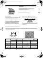
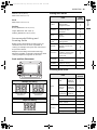
OWNER'S MANUAL
ELECTRIC
INDUCTION RANGE
Read this owner's manual thoroughly before operating the
appliance and keep it handy for reference at all times.
ENGLISH
LSIL6336*E
MFL68920560
Rev.02_103023
www.lg.com
Copyright © 2023 LG Electronics Inc. All Rights Reserved.
Scan to see the online manual.
en-us_main.book.book Page 1 Friday, October 27, 2023 11:23 AM

TABLE OF CONTENTS
2
4 IMPORTANT SAFETY
INSTRUCTIONS
4 READ ALL INSTRUCTIONS BEFORE USE
4 Safety Messages
4 Anti-tip Device
5 WARNING
5 Installation
5 Operation
6 Maintenance
6Risk of Fire and Flammable Materials
7CAUTION
7 Operation
7 Maintenance
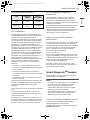
8 PRODUCT OVERVIEW
8 Product Features
8 Exterior & Interior
8 Product Specifications
9 Accessories
10 INSTALLATION
10 Before Installing
10 Installation Overview
10 Tools Needed
11 Parts
11 Unpacking and Moving the Range
13 Choosing the Proper Location
13 Dimensions and Clearances
15 Electricity
15 Flooring
15 Ambient Temperature
16 Leveling
16 Leveling the Range
16 Connecting Electricity
16 Electrical Requirements
17 Connecting the Power Cord / Conduit
21 Optional Rear Filler
21 Installing the Rear Filler
21 Anti-tip Device
21 Installing the Anti-tip Device
22 Test Run
22 Test the Range Before Use
24 OPERATION
24 Control Panel
24 Control Panel Features
25 Knob Features
26 Changing Oven Settings
26 Clock
26 Oven Light
26 Timer On/Off
26 Wi-Fi
27 Settings (Hour Mode, Convection Auto
Conversion, Calibrating the Oven
Temperature, Preheat Alarm Light, Beeper
Volume, Fahrenheit or Celsius, Cooktop on
Alert Volume, Wi-Fi On/Off)
29 Control Lock
29 Start Time (Delayed Timed Cook)
30 Cook Time (Timed Cook)
31 Minimum & Maximum Default Settings
32 Cooktop
32 Precautions when using the Cooktop
33 Cooking Areas
33 Benefits of Induction Surface Cooking
33 Induction Cookware
34 Cookware Placement
35 Pan Sensing
35 Minimum and Maximum Pan Size
36 Cookware Heating Index
37 Home Canning
37 Using the Cooking Elements
37 The Recommended Surface Cooking
Setting
38 Power Management
38 Turning on the Warm Zone
39 Oven
39 Before Using the Oven
39 Oven Vent
39 Using Oven Racks
40 Instaview
40 Bake
41 Convection Mode
42 Meat Probe
43 Recommended Baking and Roasting Guide
44 Broil
en-us_main.book.book Page 2 Friday, October 27, 2023 11:23 AM

3
44 Recommended Broiling Guide
46 Proof
47 Warm
47 Keep Warm
48 Air Fry
49 Recommended Air Frying Guide
50 Air Sous-Vide
51 Recommended Air Sous-Vide Guide
51 Frozen Meal
51 Remote Start
52 Using the Sabbath Mode
53 SMART FUNCTIONS
53 LG ThinQ Application
53 LG ThinQ Application Features
53 Installing LG ThinQ Application and
Connecting an LG Appliance
54 Installing the LG ThinQ Application
54 Connecting to Wi-Fi
54 LG UP Feature
55 RF Module Specifications
55 FCC Statement
55 FCC RF Radiation Exposure Statement
55 Open Source Software Notice Information
55 Smart DiagnosisTM Feature
55 Using LG ThinQ to Diagnose Issues
56 Using Audible Diagnosis to Diagnose
Issues
57 MAINTENANCE
57 Cleaning
57 Interior
57 Exterior
59 Cooktop Surface
62 EasyClean
64 Self Clean
66 Removing/Assembling Lift-Off Oven Doors
67 Removing/Assembling Drawers
68 Removing/Assembling the Vent Trim
68 Periodic Maintenance
68 Changing the Oven Light
70 TROUBLESHOOTING
70 FAQs
70 Frequently Asked Questions
72 Before Calling for Service
72 Cooking
74 Parts & Features
76 Noises
77 Wi-Fi
78 LIMITED WARRANTY
78 USA
78 TERMS AND CONDITIONS
78 THIS LIMITED WARRANTY DOES NOT
COVER:
82 PROCEDURE FOR RESOLVING DISPUTES:
en-us_main.book.book Page 3 Friday, October 27, 2023 11:23 AM

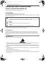
4IMPORTANT SAFETY INSTRUCTIONS
IMPORTANT SAFETY INSTRUCTIONS
READ ALL INSTRUCTIONS BEFORE USE
Download this owner's manual at http://www.lg.com
Safety Messages
Your safety and the safety of others are very important.
We have provided many important safety messages in this manual and on your appliance. Always read and
follow all safety messages.
All safety messages will tell you what the potential hazard is, tell you how to reduce the chance of injury,
and tell you what may happen if the instructions are not followed.
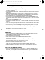
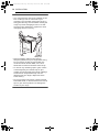
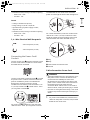
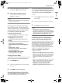
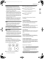
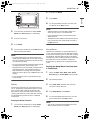
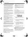
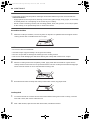
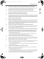
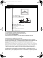
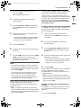
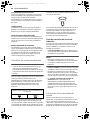
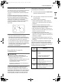
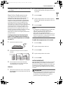
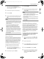
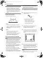
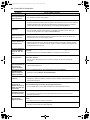
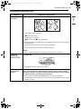
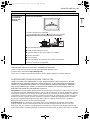
Anti-tip Device
To reduce the risk of tipping, the appliance must be secured by a properly installed anti-tip device. To
check if the device is installed properly, verify that the anti-tip device is engaged, or grasp the top rear
edge of the range back guard and carefully attempt to tilt it forward. Refer to the installation section for
instructions.
WARNING
• A child or adult can tip the range and be killed.
• Install the anti-tip device to the structure and/or the range. Verify the anti-tip device has been properly
installed and engaged by following the guide on the anti-tip bracket template.
• Engage the range to the anti-tip device by following the guide on the anti-tip bracket template. Ensure
the anti-tip device is re-engaged when the range is moved by following the guide on the anti-tip bracket
template.
• Re-engage the anti-tip device if the range is moved. Do not operate the range without the anti-tip device
in place and engaged.
• See installation instructions for details.
• Failure to do so can result in death or serious burns to children or adults.
• Do not rest large, heavy items such as whole turkeys on the open oven door. The range could tip forward
and cause injury.
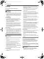
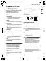
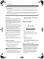
This is the safety alert symbol.
This symbol alerts you to potential hazards that can kill or injure you and others. All safety messages
will follow the safety alert symbol and either the word WARNING or CAUTION.
These words mean:
WARNING
You may be killed or seriously injured if you do not follow instructions.
CAUTION
You may be injured or cause damage to the product if you do not follow instructions.
en-us_main.book.book Page 4 Friday, October 27, 2023 11:23 AM

5IMPORTANT SAFETY INSTRUCTIONS
ENGLISH
• Do not step or sit on the oven door. The range could be tipped and injury might result from spilled hot
liquid, food, or the range itself.
• Never remove the oven legs. The range will not be secured to the anti-tip bracket if the legs are
removed.
WARNING
WARNING
• To reduce the risk of explosion, fire, death, electric shock, injury or scalding to persons when using this
product, follow basic precautions, including the following:
Installation
• Do not line the oven walls, racks, bottom, or any other part of the oven with aluminum foil or any other
material. Doing so will disrupt heat distribution, produce poor baking results and cause permanent
damage to the oven interior. (Aluminum foil will melt to the interior surface of the oven.)
• To eliminate the risk of burns or fire by reaching over heated surface units, cabinet storage space
located above the surface units should be avoided. If cabinet storage is to be provided, the risk can be
reduced by installing a range hood that projects horizontally a minimum of 5 inches beyond the bottom
of the cabinets.
• Do not use aluminum foil or any other material to line the oven bottom. Improper installation of these
liners may result in a risk of electric shock or fire.
• Make sure your range is properly installed and grounded by a qualified installer, according to the
installation instructions. Any adjustment and service should be performed only by qualified range
installers or service technicians.
Operation
• Do not leave children alone or unsupervised near the appliance when it is in use or is still hot. Children
should never be allowed to sit or stand on any part of the appliance as they could be injured or burned.
• Children should not be allowed to play with controls or other parts of the appliance.
• DO NOT TOUCH HEATING ELEMENTS OR INTERIOR SURFACES OF OVEN. Heating elements may be hot
even though they are dark in color. Interior surfaces of an oven become hot enough to cause burns.
During and after use, do not touch or let clothing or other flammable materials contact heating elements
or interior surfaces of the oven until they have had sufficient time to cool. Other surfaces, such as oven
vent openings and surfaces near these openings, oven doors, and windows of oven doors, also get hot
and may cause burns if not cooled.
• Surface units may be hot even though they are dark in color. Areas near surface units may become hot
enough to cause burns. During and after use, DO NOT TOUCH SURFACE UNITS OR AREAS NEAR UNITS or
let clothing or other flammable materials contact surface units or areas near units until they have had
sufficient time to cool. This includes the cooktop and the area above the oven door.
• Use care when opening the oven door. The hot air and steam that escape can cause burns to hands, face
and eyes. Let hot air or steam escape from the oven before removing or replacing food in the oven.
• Do not use plastic to cover food. Use foil or oven-safe lids only.
aAnti-tip bracket
bLeveling leg
en-us_main.book.book Page 5 Friday, October 27, 2023 11:23 AM

6IMPORTANT SAFETY INSTRUCTIONS
• Never attempt to dry a pet in the oven.
• Never use your appliance for warming or heating the room.
• Always use pot holders or oven mitts when removing food from the oven or the surface element.
Cookware will be hot. Use only dry pot holders. Moist or damp pot holders on hot surfaces may result in
burns from steam. Do not let the pot holder touch hot heating elements. Do not use a towel or other
bulky cloth to remove food.
• Do not heat unopened food containers. Pressure in the containers may cause them to burst which may
result in injury.
• Be certain that all packing materials are removed from the appliance before operating. Keep plastic,
clothes, paper, and other flammable materials away from parts of the appliance that may become hot.
• Do not allow aluminum foil or the temperature probe to contact heating elements.
• Do not touch the hot surface between the bottom of the oven door and the top of the drawer on the
front of the oven while the oven is in operation. The surface becomes hot and can cause burns and other
injury.
• Do not touch the oven racks while they are hot.
• If a rack must be moved while the oven is hot, do not let the pot holder contact the hot heating element
in the oven.
• Pull the oven rack to the stop-lock position when loading and unloading food from the oven. This helps
prevent burns caused by touching hot surfaces of the door and oven walls.
• Do not use the oven if a heating element develops a glowing spot during use or shows other signs of
damage. A glowing spot indicates the heating element may fail and present a potential burn, fire, or
shock hazard. Turn the oven off immediately and have the heating element replaced by a qualified
service technician.
• During oven operation, the upper surface of the drawer cavity becomes hot and may cause burns. Never
allow children to remain unsupervised near the oven or cooktop.
• Do not put your hand inside the drawer while the oven is operating.
Maintenance
• Do not store items of interest to children in cabinets above a range or on the back guard of a range.
Children climbing on the range to reach items could be seriously injured.
• Do not allow children to crawl into the oven.
• Let hot cookware and utensils cool in a safe place, out of reach of small children.
• If the door glass, cooktop glass, surface, or oven heating unit of the range are damaged, discontinue use
of the range and call for service.
• Do not allow anyone to climb, stand or hang on the door, storage drawer or cooktop. They could
damage the range and even tip it over, causing severe personal injury.
• Always disconnect power from the appliance before servicing.
• Before replacing the oven light, switch off the electrical power to the oven at the main fuse or circuit
breaker panel. Failure to do so can result in severe personal injury, death, or electrical shock.
• Never pour cold water over a hot oven for cleaning. Doing so may cause the oven to malfunction.
Risk of Fire and Flammable Materials
• Do not store or use flammable material in the oven or near or on the cooktop. Flammable materials
include paper, plastic, pot holders, linens, wall coverings, curtains, and gasoline or other flammable
vapors and liquids such as grease or cooking oil. These materials can be ignited when the oven and
cooktop are in use.
• Use extreme caution when moving or disposing of hot grease.
en-us_main.book.book Page 6 Friday, October 27, 2023 11:23 AM

7IMPORTANT SAFETY INSTRUCTIONS
ENGLISH
SAVE THESE INSTRUCTIONS
• Wear proper apparel. Do not wear loose-fitting or hanging garments, which may ignite if they contact
hot surfaces, and cause severe burns.
• Do not use the oven for drying clothes. Only use the oven for its intended purpose.
• If cabinet storage is provided directly above the cooking surface, only use it to store items that are not
frequently used and can be safely stored in an area subjected to heat. Temperatures may be unsafe for
volatile items such as flammable liquids, cleaners or aerosol sprays.
• Do not use water on grease fires. Should an oven fire occur, leave the oven door closed and turn the
oven off. If the fire continues, throw baking soda on the fire or use a fire extinguisher. Do not put water
or flour on the fire. Flour may be explosive and water can spread a grease fire and cause personal injury.
CAUTION
CAUTION
• To reduce the risk of minor injury to persons, malfunction, or damage to the product or property when
using this product, follow basic precautions, including the following:
Operation
• Always heat fat slowly, and watch as it heats.
• If frying combinations of oils and fats, stir them together before heating.
• Use a deep fat thermometer, if possible, to prevent overheating fat beyond the smoking point.
• Use the least possible amount of fat for effective shallow or deep-fat frying. Filling the pan with too much
fat can cause spillovers when food is added.
• Accessible parts may become hot when the broiler is in use.
• Do not place food or cookware on the bottom of the oven cavity. Doing so will cause permanent damage
to the oven bottom finish.
• When using cooking or roasting bags in the oven, follow the manufacturer’s directions.
Maintenance
• Do not repair or replace any part of the appliance unless specifically recommended in the manual. All
other servicing should be performed by a qualified technician.
• Do not use harsh etching, abrasive cleaners or sharp metal scrapers to clean the oven door glass
because they can scratch the surface. Scratches may cause the glass to shatter.
• Make sure oven lights are cool before cleaning.
• Do not clean the door gasket. The door gasket is essential for a good seal. Care should be taken not to
rub, damage, or move the gasket.
• Clean in the self-clean cycle only parts listed in this manual. Before self-cleaning the oven, remove the
broiler pan, all oven racks, the meat probe and any cookware, utensils or food from the oven.
en-us_main.book.book Page 7 Friday, October 27, 2023 11:23 AM

8PRODUCT OVERVIEW
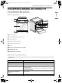
PRODUCT OVERVIEW
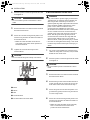
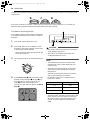
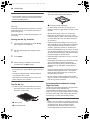
Product Features
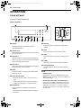
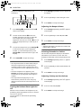
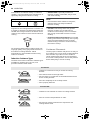
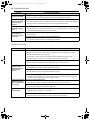
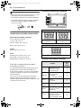
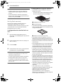
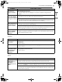
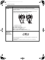
Exterior & Interior
aCooktop
bCooktop Controller
cOven Door
dStorage Drawer
eOven Mode Knob
fGasket
gModel & Serial Number Plate
hBroil Heater
iConvection Heater
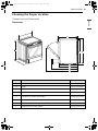
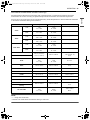
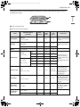
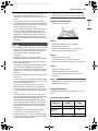
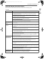
Product Specifications
The appearance and specifications listed in this manual may vary due to constant product improvements.
Oven Range Models LSIL6336*E
Description Electric Slide In Oven Range
Electrical requirements 11.9 kW 120/240 VAC or 10.2 kW 120/208 VAC
Exterior Dimensions 29 7/8" (W) x 36 1/2" (H) x 26 7/8" (D) (D with door closed)
75.8 cm (W) x 92.7 cm (H) x 68.3 cm (D) (D with door closed)
Height to cooking surface 36" (91.3 cm)
Net weight 186.1 lb (84.4 kg)
Total capacity 6.3 cu. ft.
en-us_main.book.book Page 8 Friday, October 27, 2023 11:23 AM

9PRODUCT OVERVIEW
ENGLISH
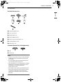
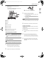
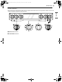
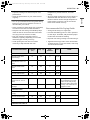
Accessories
Included Accessories
aHeavy Duty Rack (2 ea)
bAir Fry Tray (1 ea)
cMeat Probe (1 ea)
dOwner’s Manual (1 ea)
eNon-scratch Scouring Pad (1 ea)
fCooktop Cleaner (1 ea)
gRear Filler (1 ea)
Optional Accessories (sold separately)
aGrid
bBroiler Pan
NOTE
• Contact LG Customer Service at 1-800-243-0000
(1-888-542-2623 in Canada) if any accessories
are missing.
• For your safety and for extended product life,
only use authorized components.
• The manufacturer is not responsible for product
malfunction or accidents caused by the use of
separately purchased, unauthorized
components or parts.
• The images in this guide may be different from
the actual components and accessories, which
are subject to change by the manufacturer
without prior notice for product improvement
purposes.
Cleaner
en-us_main.book.book Page 9 Friday, October 27, 2023 11:23 AM

10 INSTALLATION
INSTALLATION
Before Installing
Installation Overview
Please read the following installation instructions first after purchasing this product or transporting it to
another location.
The images in this guide may be different from the actual components and accessories, which are subject
to change by the manufacturer without prior notice for product improvement purposes.
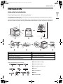
Tools Needed aPhillips Screwdriver
bFlat-blade Screwdriver
c1/4" Nut Driver
dPliers
eTape Measure
fLevel
gAdjustable Wrench
a Check and choose the proper location e Install anti-tip device
b Level the range f Engage the anti-tip device
c Connect electric range g Test run
d Plug in the power cord
en-us_main.book.book Page 10 Friday, October 27, 2023 11:23 AM

11INSTALLATION
ENGLISH
hDrill
iSafety Glasses
jGloves
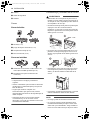
Parts
Parts Provided
aTemplate (1 ea)
bAnti-tip Bracket Kit (1 ea)
cAnchor Sleeves (6 ea)
dLag Bolts (6 ea)
Parts Not Provided
a4-Wire Cord or 3-Wire Cord (UL approved 40 or
50 AMP)
bStrain Relief (for conduit installations only)
NOTE
• Observe all governing codes and ordinances.
• Have the installer show you the location of the
circuit breaker or fuse. Mark it for easy
reference.
• As when using any appliance generating heat,
there are certain safety precautions you should
follow.
• Be sure your range is installed and grounded
properly by a qualified installer or service
technician.
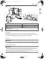
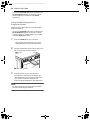
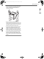
Unpacking and Moving the Range
WARNING
• You should use two or more people to move and
install the range. (Excessive Weight Hazard)
Failure to do so can result in back or other injury.
• Do not use the door handles or knobs to push or
pull the range during installation or when
moving the range out for cleaning or service.
Doing so can result in serious damage to the
range.
• Do not push or pull the range by grabbing the
open oven door or cooktop only. Doing so can
result in serious damage to the range.
• Do not lift the range using the cooktop or door
handle. Doing so can cause damage and
improper operation of the range.
• To reduce the risk of burns, do not move this
appliance while it is hot.
NOTE
• The image may differ from the actual model.
en-us_main.book.book Page 11 Friday, October 27, 2023 11:23 AM

12 INSTALLATION
NOTE
• Your range is heavy and can be installed on soft
floor coverings such as cushioned vinyl or
carpeting. Use care when moving the range on
this type of flooring. Use a belt when moving the
range to prevent damaging the floor. Or slide
the range onto cardboard or plywood to avoid
damaging the floor covering.
• Remove packing material, tape and any
temporary labels from your range before using.
Do not remove any warning-type labels, the
model and serial number label, or the Tech
Sheet that is located on the back of the range.
• To remove any remaining tape or glue, rub the
area briskly with your thumb. Tape or glue
residue can also be easily removed by rubbing a
small amount of liquid dish soap over the
adhesive with your fingers. Wipe with warm
water and dry.
• Do not use sharp instruments, rubbing alcohol,
flammable fluids, or abrasive cleaners to remove
tape or glue. These products can damage the
surface of your range.
en-us_main.book.book Page 12 Friday, October 27, 2023 11:23 AM

13INSTALLATION
ENGLISH
Choosing the Proper Location
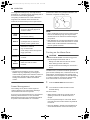
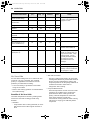
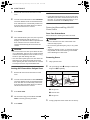
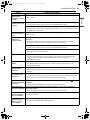
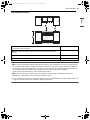
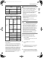
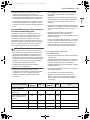
Dimensions and Clearances
Dimensions
-Dimensions LSIL6336*E
AWidth 29 7/8" (758.8 mm)
BHeight 36 1/2" (927.9 mm)
C Depth (Includes Door Handle) 29 5/16" (743.9 mm)
D Height (Excludes Vent Trim) 36" (913.0 mm)
EDepth (Includes only the product body that is loaded into the cabinet.
Excludes door, drawer, and handles) 24 3/4" (629.4 mm)
F Depth (Excludes Door Handle) 26 7/8" (683 mm)
G Depth when drawer is fully opened 36 1/16" (916.2 mm)
H Depth when door is fully opened 48 5/8" (1235.9 mm)
en-us_main.book.book Page 13 Friday, October 27, 2023 11:23 AM

14 INSTALLATION
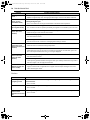
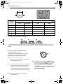
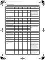
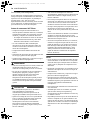
Minimum Dimensions
NOTE
•a 30" (76.2 cm) minimum clearance between the top of the cooking surface and the bottom of an
unprotected wood or metal cabinet; or 24" (60.9 cm) minimum when bottom of wood or metal cabinet is
protected by not less than 1/4" (6.4 cm) flame retardant millboard covered with not less than no. 28 MSG
sheet steel, 0.015" (0.381 mm) stainless steel, 0.024" (0.610 mm) aluminum or 0.020" (0.508 mm) copper.
•b 15" (38.1 cm) minimum between countertop and adjacent cabinet bottom.
• Important – Save for the use of the local electrical inspector.
• For installation in Canada, a free-standing range is not to be installed closer than 15/32" (12 mm) from
any adjacent surface.
a Minimum distance from top of range to combustible surface overhead 30" (76.2 cm)
b Minimum distance from countertop to overhead cabinets at side 15" (38.1 cm)
c Minimum opening in overhead cabinets 30" (76.2 cm)
d Height of countertop 36" (91.3 cm)
en-us_main.book.book Page 14 Friday, October 27, 2023 11:23 AM

15INSTALLATION
ENGLISH
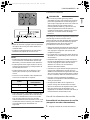
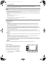
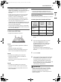
Clearances
Electricity
The range should always be plugged into its own individual properly grounded electrical outlet.
• This prevents overloading house wiring circuits which could cause a fire hazard from overheated wires.
• It is recommended that a separate circuit serving only this appliance be provided.
Flooring
CAUTION
• Use an insulated pad or 1/4 in. (0.64 cm) plywood under the range if installing the range over carpeting.
Ambient Temperature
CAUTION
• Make sure wall coverings, countertops and cabinets around the range can withstand the heat (up to 194
°F) generated by the range. Discoloration, delamination or melting may occur. This range has been
designed to comply with the maximum allowable wood cabinet temperature of 194 °F.
• Before installing the range in an area covered with linoleum or other synthetic floor covering, make sure
the floor covering can withstand temperatures of at least 200 °F (93 °C).
a Acceptable Electrical Outlet Area b Normal Countertop Depth
c Counter Top Height d Cabinet
e Wall f Center
g Cabinet Opening
= 30" (76.2 cm) For U.S.A
= 30" (76.2 cm) ~ 31" (78.7 cm) For CANADA
en-us_main.book.book Page 15 Friday, October 27, 2023 11:23 AM

16 INSTALLATION
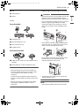
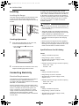
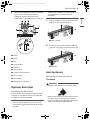
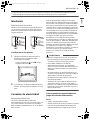
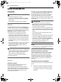
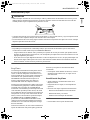
Leveling
Leveling the Range
Level the range by adjusting the leveling legs with
a wrench. Extending the legs slightly may also
make it easier to insert the rear leg into the anti-tip
bracket.
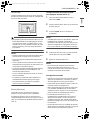
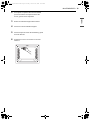
Checking Adjustments
1 Place the level diagonally on the oven rack,
and check each direction for level.
• First check direction a. Then check
direction b.
2 If the level doesn’t show that the rack is level,
adjust the leveling legs with a wrench.
Connecting Electricity
Electrical Requirements
This appliance must be installed and grounded on
a branch circuit by a qualified technician in
accordance with the National Electrical code ANSI/
NFPA NO. 70 - latest edition.
All wiring should conform to local and NEC codes.
This range requires a single-phase, 3 wire, AC 120/
208 V or 120/240 V 60 Hz electrical system. Use
only a 3-conductor or a 4-conductor UL - listed
range cord with closed-loop terminals, open-end
spade lugs with upturned ends or similar
termination. Do not install the power cord without
a strain relief.
A range cord rated at 40 amps with 120/240
minimum volt range is required. If a 50 amp range
cord is used, it should be marked for use with 13/
8" diameter connection openings. This appliance
may be connected by means of a conduit or power
cord. If a conduit is being used, refer to "3-Wire
Connection: Conduit" or "4-Wire Connection:
Conduit" sections.
WARNING
• Allow 2 to 3 ft (61.0 cm to 91.4 cm) of slack in the
line so that the range can be moved if servicing
is ever necessary.
• The power supply cord and plug should not be
modified. If it will not fit the outlet, have a proper
outlet installed by a qualified electrician.
• Using an extension cord to connect the power is
prohibited. Connect the power cord and plug
directly.
• Electrical ground is required on this appliance.
• Make sure that the power cord is not pinched by
the range or heavy objects. Failure to do so can
result in serious burns or electrical shock.
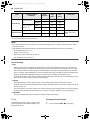
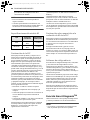
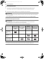
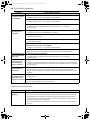
Specified Power Cord Kit Rating
Case 1
• Voltage: 120/240 volts (3-wire)
• Range rating: 8,750 W - 16,500 W
• Specified rating of power supply-cord kit,
amperes: 40 A or 50 A
• Diameter (inches) of range connection opening
- Power cord: 1 3/8"
- Conduit: 1 1/8"
Case 2
• Voltage: 120/240 volts (3-wire)
• Range rating: 16,501 W - 22,500 W
• Specified rating of power supply-cord kit,
amperes: 50 A
• Diameter (inches) of range connection opening
- Power cord: 1 3/4"
- Conduit: 1 3/8"
Case 3
• Voltage: 120/208 volts (3-wire)
• Range rating: 7,801 W- 12,500 W
• Specified rating of power supply-cord kit,
amperes: 40 A or 50 A
en-us_main.book.book Page 16 Friday, October 27, 2023 11:23 AM

17INSTALLATION
ENGLISH
• Diameter (inches) of range connection opening
- Power cord: 1 3/8"
- Conduit: 1 1/8"
Case 4
• Voltage: 120/208 volts (3-wire)
• Range rating: 12,501 W - 18,500 W
• Specified rating of power supply-cord kit,
amperes: 50 A
• Diameter (inches) of range connection opening
- Power cord: 1 3/4"
- Conduit: 1 3/8"
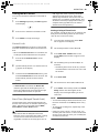
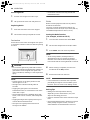
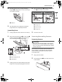
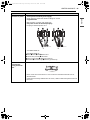
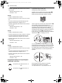
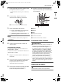
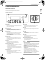
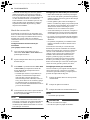
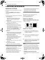
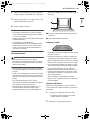
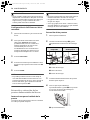
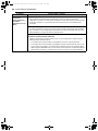
3, 4 - Wire Electrical Wall Receptacle
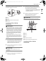
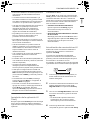
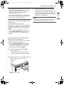
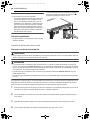
Connecting the Power Cord /
Conduit
The rear access cover a must be removed. Loosen
the two screws with a screwdriver. The terminal
block will then be accessible.
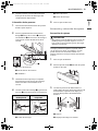
Use the cord/conduit connection plate b to install
the power cord or conduit. Leave the connection
plate as installed for power cord installations.
Remove the connection plate for conduit
installations and rotate it to use the smaller 1 1/8
in. (2.8 cm) conduit hole c instead of the 1 3/8 in.
(3.5 cm) power cord hole d.
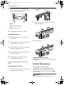
For power cord e installations, hook the strain
relief over the 1 3/8 in. (3.5 cm) power cord hole
located below the rear of the oven. Insert the
power cord through the strain relief and tighten it.
For conduit installations, insert the conduit strain
relief in the 1 1/8 in. (2.8 cm) conduit hole. Then
install the conduit through the body of the strain
relief and fasten the strain relief with its ring.
f Ring
g Body
h Cord/Conduit Connection Plate
i Conduit
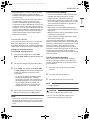
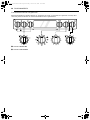
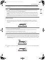
3-Wire Connection: Power Cord
WARNING
• The white middle (neutral or ground) wire of a 3-
wire power cord or a 3-wire conduit has to be
connected to the middle post of the main
terminal block. The remaining two wires of the
power cord or conduit have to be connected to
the outside posts of the main terminal
connection block. Failure to do so can result in
electrical shock, severe personal injury or death.
• If screws are not tightened securely, it can result
in electrical spark and severe personal injury or
death.
1 For power cord installations, hook the strain
relief over the power cord hole (1 3/8") located
below the rear of the oven.
4 Wire receptacle (14-50R)
3 Wire receptacle (10-50R)
1
1
/
8
"
(2.8 cm)
1
3
/
8
"
(3.5 cm)
en-us_main.book.book Page 17 Friday, October 27, 2023 11:23 AM

18 INSTALLATION
2 Insert the power cord through the strain relief
and tighten it.
CAUTION
• Do not install the power cord without a strain
relief.
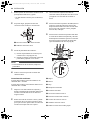
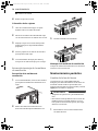
3 Remove the lower 3 screws from the terminal
block and retain them.
4 Insert the 3 screws through each power cord
terminal ring and into the lower terminals of
the terminal block.
• Make sure that the white center wire is
connected to the center lower position of
the terminal block.
5 Tighten the 3 screws securely into the
terminal block.
CAUTION
• Do not remove the ground strap connections.
aBlack
bWhite
cRed
dTerminal Block
eCord/Conduit Connection Plate
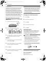
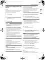
4-Wire Connection: Power Cord
WARNING
• Only a 4-conductor power-supply cord kit rated
120/240 volts, 50 amperes and marked for use
with ranges with closed-loop connectors or
opened spade lugs with upturned ends must be
used. The white middle (neutral) wire of the
power cord or 4-wire conduit has to be
connected to the middle post of the main
terminal block. The other two wires of the power
cord or conduit have to be connected to the
outside posts of the main terminal connection
block. The 4th ground wire (green) must be
connected to the frame of the range with the
ground screw. Failure to do so can result in
electrical shock, severe personal injury or death.
• If screws are not tightened securely, it can result
in electrical spark and severe personal injury or
death.
1 For power cord installations, hook the strain
relief over the power cord hole (1 3/8") located
below the rear of the oven.
2 Insert the power cord through the strain relief
and tighten it.
CAUTION
• Do not install the power cord without a strain
relief.
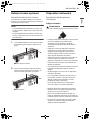
3 Remove the lower 3 screws from the terminal
block and retain them.
4 Remove the ground screw and bend the end
of the ground strap up so the slot is over the
hole of the center screw removed in step 3.
5 Insert the ground screw into the power cord
ground wire (green) terminal ring and secure
it to the range frame.
6 Insert the 3 screws through each power cord
terminal ring and into the lower terminals of
the terminal block.
• Make sure that the white center (neutral)
wire is connected to the center lower
position of the terminal block.
en-us_main.book.book Page 18 Friday, October 27, 2023 11:23 AM

19INSTALLATION
ENGLISH
7 Tighten the 3 screws securely into the
terminal block.
• The center screw now attaches the bent up
ground strap to the block.
aBlack
bWhite
cRed
dTerminal Block
eGround Strap
fGround Screw
gCord/Conduit Connection Plate
hBend strap up and attach.
3-Wire Connection: Conduit
WARNING
• If screws are not tightened securely, it can result
in electrical spark and severe personal injury or
death.
Conduit Installations
CAUTION
• Do not install the conduit without a strain relief.
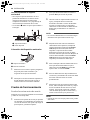
1 Remove the cord/conduit connection plate
from the rear of the oven and rotate it.
• The conduit hole (1 1/8") must be used.
2 Prepare the conduit wires as shown below.
aCord/Conduit connection plate
3 Install the conduit strain relief.
1) Insert the strain relief in the 1 1/8 in. (2.8
cm) conduit hole.
2) Install the conduit through the body of
the strain relief and fasten the strain relief
with its ring.
NOTE
• For conduit installations, purchase a strain relief.
4 Reinstall the cord/conduit connection plate.
Conduit Connections
If the wire in the conduit is copper it must be 8 or
10 AWG wiring.
If the wire in the conduit is aluminum it must be 6
or 8 AWG wiring.
1 Loosen the lower 3 screws from the terminal
block.
2 Insert the bare wire (white/neutral) end
through the center terminal block opening.
Do not remove the ground strap connections.
3 Insert the two side bare wire ends into the
lower left and the lower right terminal block
openings.
en-us_main.book.book Page 19 Friday, October 27, 2023 11:23 AM

20 INSTALLATION
4 Tighten the 3 screws securely into the
terminal block. (approximately 35 - 50 IN-LB)
aBlack
bWhite
cRed
dTerminal Block
eWire Ends
fConduit Connection Plate
4-Wire Connection: Conduit
WARNING
• The white middle (neutral) wire of the power
cord or 4-wire conduit has to be connected to
the middle post of the main terminal block. The
other two wires of the power cord or conduit
have to be connected to the outside posts of the
main terminal connection block. The 4th ground
wire (green) must be connected to the frame of
the range with the ground screw. Failure to do
so can result in electrical shock, severe personal
injury or death.
• If screws are not tightened securely, it can result
in electrical spark and severe personal injury or
death.
Conduit Installations
CAUTION
• Do not install the conduit without a strain relief.
1 Remove the cord/conduit connection plate
from the rear of the oven and rotate it.
• The conduit hole (1 1/8") must be used.
2 Prepare the conduit wires as shown below.
aCord/Conduit Connection Plate
bGround Wire
3 Install the conduit strain relief.
1) Insert the strain relief in the 1 1/8 in. (2.8
cm) conduit hole.
2) Install the conduit through the body of
the strain relief and fasten the strain relief
with its ring.
NOTE
• For conduit installations, purchase a strain relief.
4 Reinstall the cord/conduit connection plate.
Conduit Connections
If the wire in the conduit is copper it must be 8 or
10 AWG wiring.
If the wire in the conduit is aluminum it must be 6
or 8 AWG wiring.
1 Loosen the 2 lower left and right screws from
the terminal block. Remove the lower 2 center
screws. Do not discard any screws.
2 Remove the ground screw and bend the end
of the ground strap up so the slot is over the
hole of the center screw removed in step 1.
3 Attach the ground (green) bare wire end to
the range frame and secure it in place with
the ground screw.
4 Insert the bare wire (white/neutral) end
through the center terminal block opening.
The center screw now attaches the bent up
ground strap to the block.
en-us_main.book.book Page 20 Friday, October 27, 2023 11:23 AM
Page is loading ...
Page is loading ...
Page is loading ...
Page is loading ...
Page is loading ...
Page is loading ...
Page is loading ...
Page is loading ...
Page is loading ...
Page is loading ...
Page is loading ...
Page is loading ...
Page is loading ...
Page is loading ...
Page is loading ...
Page is loading ...
Page is loading ...
Page is loading ...
Page is loading ...
Page is loading ...
Page is loading ...
Page is loading ...
Page is loading ...
Page is loading ...
Page is loading ...
Page is loading ...
Page is loading ...
Page is loading ...
Page is loading ...
Page is loading ...
Page is loading ...
Page is loading ...
Page is loading ...
Page is loading ...
Page is loading ...
Page is loading ...
Page is loading ...
Page is loading ...
Page is loading ...
Page is loading ...
Page is loading ...
Page is loading ...
Page is loading ...
Page is loading ...
Page is loading ...
Page is loading ...
Page is loading ...
Page is loading ...
Page is loading ...
Page is loading ...
Page is loading ...
Page is loading ...
Page is loading ...
Page is loading ...
Page is loading ...
Page is loading ...
Page is loading ...
Page is loading ...
Page is loading ...
Page is loading ...
Page is loading ...
Page is loading ...
Page is loading ...
Page is loading ...
Page is loading ...
Page is loading ...
Page is loading ...
Page is loading ...
Page is loading ...
Page is loading ...
Page is loading ...
Page is loading ...
Page is loading ...
Page is loading ...
Page is loading ...
Page is loading ...
Page is loading ...
Page is loading ...
Page is loading ...
Page is loading ...
Page is loading ...
Page is loading ...
Page is loading ...
Page is loading ...
Page is loading ...
Page is loading ...
Page is loading ...
Page is loading ...
Page is loading ...
Page is loading ...
Page is loading ...
Page is loading ...
Page is loading ...
Page is loading ...
Page is loading ...
Page is loading ...
Page is loading ...
Page is loading ...
Page is loading ...
Page is loading ...
Page is loading ...
Page is loading ...
Page is loading ...
Page is loading ...
Page is loading ...
Page is loading ...
Page is loading ...
Page is loading ...
Page is loading ...
Page is loading ...
Page is loading ...
Page is loading ...
Page is loading ...
Page is loading ...
Page is loading ...
Page is loading ...
Page is loading ...
Page is loading ...
Page is loading ...
Page is loading ...
Page is loading ...
Page is loading ...
Page is loading ...
Page is loading ...
Page is loading ...
Page is loading ...
Page is loading ...
Page is loading ...
Page is loading ...
Page is loading ...
Page is loading ...
Page is loading ...
Page is loading ...
Page is loading ...
Page is loading ...
Page is loading ...
Page is loading ...
Page is loading ...
Page is loading ...
Page is loading ...
Page is loading ...
Page is loading ...
Page is loading ...
Page is loading ...
Page is loading ...
Page is loading ...
Page is loading ...
Page is loading ...
Page is loading ...
Page is loading ...
Page is loading ...
Page is loading ...
Page is loading ...
Page is loading ...
Page is loading ...
Page is loading ...
Page is loading ...
Page is loading ...
Page is loading ...
Page is loading ...
-
 1
1
-
 2
2
-
 3
3
-
 4
4
-
 5
5
-
 6
6
-
 7
7
-
 8
8
-
 9
9
-
 10
10
-
 11
11
-
 12
12
-
 13
13
-
 14
14
-
 15
15
-
 16
16
-
 17
17
-
 18
18
-
 19
19
-
 20
20
-
 21
21
-
 22
22
-
 23
23
-
 24
24
-
 25
25
-
 26
26
-
 27
27
-
 28
28
-
 29
29
-
 30
30
-
 31
31
-
 32
32
-
 33
33
-
 34
34
-
 35
35
-
 36
36
-
 37
37
-
 38
38
-
 39
39
-
 40
40
-
 41
41
-
 42
42
-
 43
43
-
 44
44
-
 45
45
-
 46
46
-
 47
47
-
 48
48
-
 49
49
-
 50
50
-
 51
51
-
 52
52
-
 53
53
-
 54
54
-
 55
55
-
 56
56
-
 57
57
-
 58
58
-
 59
59
-
 60
60
-
 61
61
-
 62
62
-
 63
63
-
 64
64
-
 65
65
-
 66
66
-
 67
67
-
 68
68
-
 69
69
-
 70
70
-
 71
71
-
 72
72
-
 73
73
-
 74
74
-
 75
75
-
 76
76
-
 77
77
-
 78
78
-
 79
79
-
 80
80
-
 81
81
-
 82
82
-
 83
83
-
 84
84
-
 85
85
-
 86
86
-
 87
87
-
 88
88
-
 89
89
-
 90
90
-
 91
91
-
 92
92
-
 93
93
-
 94
94
-
 95
95
-
 96
96
-
 97
97
-
 98
98
-
 99
99
-
 100
100
-
 101
101
-
 102
102
-
 103
103
-
 104
104
-
 105
105
-
 106
106
-
 107
107
-
 108
108
-
 109
109
-
 110
110
-
 111
111
-
 112
112
-
 113
113
-
 114
114
-
 115
115
-
 116
116
-
 117
117
-
 118
118
-
 119
119
-
 120
120
-
 121
121
-
 122
122
-
 123
123
-
 124
124
-
 125
125
-
 126
126
-
 127
127
-
 128
128
-
 129
129
-
 130
130
-
 131
131
-
 132
132
-
 133
133
-
 134
134
-
 135
135
-
 136
136
-
 137
137
-
 138
138
-
 139
139
-
 140
140
-
 141
141
-
 142
142
-
 143
143
-
 144
144
-
 145
145
-
 146
146
-
 147
147
-
 148
148
-
 149
149
-
 150
150
-
 151
151
-
 152
152
-
 153
153
-
 154
154
-
 155
155
-
 156
156
-
 157
157
-
 158
158
-
 159
159
-
 160
160
-
 161
161
-
 162
162
-
 163
163
-
 164
164
-
 165
165
-
 166
166
-
 167
167
-
 168
168
-
 169
169
-
 170
170
-
 171
171
-
 172
172
-
 173
173
-
 174
174
-
 175
175
-
 176
176
-
 177
177
-
 178
178
-
 179
179
-
 180
180


Ask a question and I''ll find the answer in the document
Finding information in a document is now easier with AI
in other languages
- español: Yes LSIL6336FE Manual de usuario
Related papers
Other documents
-
LG LCE3610SBE User manual
-
-
LG LSDL6336D User manual
-
Signature Kitchen Suite SKSSV3001S Owner's manual
-
LG ES9428 2 Piece Kitchen Package User manual
-
LG ES9428 Series Wall Oven User manual
-
-
LG WCES6428 User manual
-
LG CBGS3028S Installation guide
-
LG MZBZ1715S User manual