
Leading Edge
ANSI Z359.14 - 2021
OSHA 1910.140, OSHA 1910.66
470-00068
V1.0 2023 Copyright Safewaze 220-00080
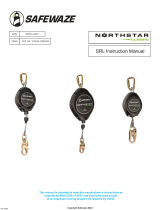
SRL Instruction Manual
OSHA 1910.140, 1910.66
This manual is intended to meet the manufacturer’s instructions as
required by ANSI Z359.14-2021 and should be used as part
of an employee training program as required by OSHA.
ANSI Z359.14-2021

TABLE OF CONTENTS
1.0 INTRODUCTION .................................................................................... 5
2.0 APPLICATION ........................................................................................ 5
3.0 APPLICABLE SAFETY STANDARDS .................................................... 5
4.0 WORKER CLASSIFICATIONS ............................................................... 6
5.0 TRAINING ............................................................................................... 6
6.0 LIMITATIONS AND REQUIREMENTS ................................................... 6
7.0 INSPECTION FREQUENCY .................................................................. 7
8.0 PURPOSE .............................................................................................. 7
9.0 SPECIFICATIONS .................................................................................. 7
10.0 ACTUAL ARREST DISTANCE/MIN REQUIRED FALL CLEARANCE ..8-11
11.0 SWING FALLS ....................................................................................... 12
12.0 FALL PROTECTION AND RESCUE PLAN ........................................... 13
13.0 NORMAL OPERATIONS ........................................................................ 13
14.0 COMPATIBILITY OF COMPONENTS ................................................... 13
15.0 COMPATIBILITY OF CONNECTORS..................................................13-14
16.0 USE .....................................................................................................14-15
17.0 PERFORMANCE ................................................................................... 15
18.0 MAINTENANCE, SERVICE, AND STORAGE ....................................... 15
19.0 INSPECTION .......................................................................................15-16
20.0 LABELING ............................................................................................. 16
Do not throw away these instructions!
Read and understand these instructions before using equipment!
User Information
Date of First Use:
Serial#:
Trainer:
User:
V1.0 2023 Copyright Safewaze

V1.0 2023 Copyright Safewaze
User must read, understand, and follow all safety and usage information contained within this manual prior to use of this equipment. Failure to follow
all safety and usage information can result in serious injury or death.
WARNINGS AND IMPORTANT PRECAUTIONS
Intended Use:
The equipment covered in this manual is intended for use as part of a complete Personal Fall Arrest System (PFAS).
Use of this equipment for any other purpose, such as material handling, sports activities, or other action not described in these User Instructions is
not approved by Safewaze. Use of this equipment in a manner outside the scope of those covered within this Manual can result in serious injury or
death. The equipment covered in this manual is only to be used by trained personnel in workplace applications.
WARNING
IMPORTANT
Safewaze Self Retracting Lifelines (SRLs) are part of a complete PFAS. Every user must be trained in the inspection, installation, operation, and proper
usage of their complete PFAS. Unapproved or inappropriate use of Safewaze SRLs could result in serious injury or death. Refer to these instructions for
the proper selection, installation, maintenance, and service of this equipment. For questions regarding use of this equipment beyond the scope of this
manual, contact Safewaze.
• The warnings below are designed to reduce the risks associated with the use of Safewaze SRLs:
• User must inspect the SRL prior to each use which includes a check for proper locking and retraction.
• If the inspection reveals an unsafe or defective condition, the SRL must be removed from service and destroyed or repaired as specied
in this manual.
• If a Safewaze SRL is exposed to fall arrest or impact forces, it must be immediately removed from service and tagged “Unusable”.
• Never allow slack to form in the SRL lifeline constituent. Never tie or knot the lifeline.
• Utilize extra caution to keep the lifeline free from any obstructions including but not limited to; surrounding objects, tools, equipment,
moving machinery, co-workers, yourself, or possible impact from overhead objects that could come into contact with the lifeline or worker.
• Avoid making sudden or quick movements as this could cause the SRL to inadvertently lock.
• Do not use a Safewaze SRL in an environment where the fall path is obstructed. Use of a Safewaze SRL on slowly shifting or unstable
material such as grain or sand, or within cramped or conned spaces, may not allow the worker to reach adequate speed for the SRL
lock up, resulting in possible engulfment.
• Work directly under the anchor point as much as possible to reduce risk of striking an object due to swing fall.
• Unused leg(s) of a harness mounted SRL must be attached to the parking component on the front of the harness.
• If the PFAS is made up of components from dierent manufacturers, ensure that all components of the PFAS are compatible with each
other and meet all applicable standards, regulations, or requirements. A Competent or Qualied Person should always review and
approve the PFAS system prior to worker use.
• Avoid lifeline contact with sharp or abrasive surfaces.
• DO NOT use combinations of components or subsystems, or both, that may aect or interfere with the safe function of each other
• DO NOT alter equipment
• DO NOT misuse equipment
• User must have a written Rescue Plan and means at hand to implement it when using this equipment. All employees should be trained
and knowledgeable in the Rescue Plan and Rescue Operations.
• Avoid exposure of this equipment to chemicals, high heat, severe cold or other harsh environments which may produce a harmful effect.
If in doubt about serviceability of this equipment, contact Safewaze.
• DO NOT use D-ring extenders of ANY TYPE when using this product in a Leading Edge environment. Extenders can interfere with the
proper function of Leading Edge SRLs and may result in serious injury or death.
• Fall protection equipment that fails inspection must be removed from service and tagged “Unusable”. The equipment should then be
returned to Safewaze for repair / service (if applicable) or destroyed. For questions regarding service / repair of components, contact
Safewaze.
• Never exceed the maximum allowable weight capacity of your fall protection equipment.
• Never exceed the maximum free fall distance of your fall protection equipment.
• Only Safewaze, or entities authorized in writing by Safewaze, may make repairs to Safewaze fall protection equipment.
• User(s) of Safewaze fall protection equipment must ensure that their health and physical condition allows them to withstand all forces
and potential risks associated with working at heights. ANSI limits the weight capacity of fall protection equipment to a maximum of
310 lbs. Some equipment covered in this manual may indicate a weight capacity in excess of 310 lbs. Although some equipment may
be rated to a higher capacity, it should be noted that heavier users are at an increased risk of serious injury or death. This being due to
increased forces on the body during a fall, and the risk for accelerated onset of suspension trauma.
• Use of a body belt is NOT authorized for fall arrest applications. Use only a Full Body Harness (FBH).
• Always wear required personal protective equipment when installing, using, or inspecting this equipment.
• If conducting training operations with this equipment, ensure that a secondary fall protection system is installed and utilized in a manner
that does not expose the trainee to unintended fall hazards.
• Immediately seek medical attention in the event a worker suffers a fall arrest incident.
• Certain subsystems may interfere with the proper operation of the equipment in this manual. Use only compatible connections. Contact
Safewaze for questions regarding compatibility of equipment or components not covered in this manual.
• Avoid objects, equipment, or surfaces that could harm the user or equipment.
• User must ensure that there is adequate fall clearance when working at height.
• Extra precautions must be taken if working in the vicinity of moving machinery, electrical hazards, chemical hazards, sharp edges,
explosive or toxic gases, extreme temperatures, or below overhead equipment or materials that could impact the user and his/her fall
protection equipment.
• If work is conducted in a high heat environment, ensure that Arc Flash or other suitable fall protection equipment is utilized.
• Users should enact the precautionary measures listed below to reduce the inherent risks of working at height:
These instructions shall be provided to the user. User must read, understand, and follow all safety and usage information contained within
this manual prior to use of this equipment. Failure to follow these instructions or improper use can result in serious injury or death.

Part
Number
SRL Class
Single Leg (S) / Dual Leg (D)
Working Length (ft.)
Lifeline Material
Lifeline Dimensions (in.)
Housing Material
Weight (lbs.)
Steel Snap Hook ①
LI Steel Swivel Snap Hook ②
ALU Snap Hook ③
Dielectric Snap Hook ④
Steel Tie Back Hook ⑤
Steel Rebar Hook ⑥
LI Steel Swivel Rebar Hook ⑦
Steel Swivel Rebar Hook ⑧
ALU Rebar Hook ⑨
Steel Captive Eye Carabiner ⑩
ALU Captive Eye Carabiner ⑪
ALU Swivel Carabiner ⑫
No Attachment
Steel Carabiner ⑬
Trip. Lock Steel Carabiner ⑭
ALU Carabiner ⑮
ALU Captive Eye Carabiner ⑪
ALU Snap Hook ③
FS-EX313 ⑯
Cab Mount Bracket ⑰
Soft Loop ⑱
Integrated BWB ⑲
1014 BWB ⑳
9012 BWB
㉑
9013 BWB
㉒
FS-FSP9020 1, 2 S 20 Steel
Cable ⌀3/16 Polymer 10.0 X X
FS-FSP9030 1, 2 S 30 Steel
Cable ⌀3/16 Polymer 13.9 X X
FS-FSP9050 1, 2 S 50 Steel
Cable ⌀3/16 Polymer 18.3 X X
Standards: ANSI Z359.14-2021
OSHA 1910.140, 1910.66
CONNECTOR ATTACHMENT
Capacity: ANSI 130-310 lbs. (59-141 kg)
OSHA Up to 420 lbs. (191kg)
V1.0 2023 Copyright Safewaze
TABLE 1 - NORTHSTAR CLASSIC LE SRL CONFIGURATION TABLE

V1.0 2023 Copyright Safewaze Page 5
ANSI Z359.14-2021 Safety Requirements for Self-Retracting Devices for Personal Fall Arrest and Rescue Systems
TABLE 2 - ANSI STANDARDS
Safewaze SRLs conform to the national standard(s) identied on their ID label. Refer to local, state, and federal (OSHA) requirements for additional information
concerning the governing of occupational safety regarding Personal Fall Arrest Systems (PFAS). Examples of product labeling are illustrated in Figure 10 of this
manual.
When used according to instructions, this product meets ANSI Z359.14-2021, OSHA 1910.140, OSHA 1910.66.
Applicable standards and regulations depend on the type of work being done, and also might include state-specic regulations. Refer to local, state, and federal
(OSHA) requirements for additional information concerning the governing of occupational safety regarding Personal Fall Arrest Systems (PFAS).
3.0 APPLICABLE SAFETY STANDARDS
Thank you for purchasing a Safewaze Self Retracting Lifeline (SRL). This manual must be read and understood in its entirety and used as part of an
employee training program as required by OSHA or any applicable state agency. This manual and any other instructional material must be provided to the user(s)
of the equipment. The user must understand how to use the SRL safely and eectively, as well as any related Personal Fall Arrest System (PFAS) components.
1.0 INTRODUCTION
2.0 APPLICATION
Safewaze SRLs are intended for use as part of a complete personal fall arrest, restraint, work positioning, suspension, or rescue system. Safewaze SRLs are
designed for a single user whose weight (including clothing, tools, and equipment) is:
ANSI 130-310 lbs. (59-141 kg)
OSHA Up to 420 lbs. (191 kg)
American National Standards Institute (ANSI) and Occupational Safety and Health Administration (OSHA):
The SRLs covered in this manual meet ANSI Z359.14-2021, and Occupational Safety and Health Administration (OSHA) regulations 1910.140, 1910.66.
ANSI requires SRLs be classied according to their intended use and are tested either as Class 1 or Class 2 units. Dynamic performance testing begins by
installing the SRL in a controlled test environment. With the SRL attached to a suitable anchorage, the lifeline constituent is attached to a test weight. The
weight is then dropped to simulate a fall arrest event. NOTE: SRL must be tested in all installation congurations allowed per its user instructions.
Test results are recorded.
Parameters recorded are:
• Arrest Distance (AD)
• Average Arrest Force (AAF)
• Maximum Arrest Force (MAF)
The Arrest Distance is the total vertical distance required to completely arrest a fall. The Arrest Distance includes the deceleration distance and the activation
distance. The Average Arrest Force is the average of the forces applied to the body and the anchorage by the fall protection system. The Maximum Arrest Force is
the maximum amount of force that may be applied to the body and the anchorage by the fall protection system. These tests are conducted in ambient conditions.
The units must also be tested in extreme atmospheric conditions. There are three conditions: Cold, Hot, and Wet (Units saturated in water and tested). Separate
units may be used for each test. All test results are recorded. This test data is then used to establish the fall clearance guidelines published in this user instruction
manual.
Class 1 and 2:
Class 1: Self-retracting devices which shall be used only on overhead anchorages and shall be subjected to a maximum free fall of 2 feet (0.6 m) or less, in
practical application.
Class 2: Self-retracting devices which are intended for applications wherein overhead anchorages may not be available or feasible and which may, in practical
application, be subjected to a free fall of no more than 6 feet (1.8 m) over an edge.
When the SRL is anchored overhead of the user, ANSI Z359.14-2021 species that both Class 1 and Class 2 SRLs shall have an arrest distance of less
than 42 in. (1.1 m). Average arrest forces must not exceed 1,350 lbs. (612.35 kg). Conditioned testing of the units allows slightly higher Average Arrest
Forces of 1,575 lbs. (714.41 kg), but Maximum Arrest Forces must always remain below 1,800 lbs. (816.47 kg).
When dynamically tested in accordance with requirements of ANSI Z359.14-2021, Class 1 and Class 2 Self-Retracting Devices must have an AAF of
1,350 lbs. (612.35 kg) or less, and an AD of less than 42 in. (1.1 m).
Class 2 SRL labels must include fall clearance table illustrations that include a diagram of the axes shown on the table. These labels shall be axed to the
product. Please see Section 10 of this user instruction manual for how to calculate your Minimum Required Fall Clearance (MRFC) using the axed labels.
Classication information found on product labels is based on test results. Table 1 indicates the SRLs covered in this manual. NOTE: Arrest distance is
one of several parts of the Minimum Required Fall Clearance (MRFC). MRFC is discussed in detail in Section 10. OSHA requires an SRL limit the free fall
to 2 feet (0.6 m) or less. If the maximum free fall distance must be exceeded, the employer must document, based on test data, that the maximum arresting
force will not be exceeded, and the personal fall arrest system will function properly.

V1.0 2023 Copyright Safewaze
Page 6
This equipment is intended to be used by persons trained in its correct application and use. It is the responsibility of the user to assure they are familiar with
these instructions and are trained in the correct care and use of this equipment. Users must be aware of the operating characteristics, application, limits, and the
consequences of improper use.
5.0 TRAINING
6.0 LIMITATIONS AND REQUIREMENTS
4.0 WORKER CLASSIFICATIONS
• Capacity: Safewaze Self Retracting Lifelines are designed in compliance with ANSI Z359.14-2021 to meet the weight capacity range of
(130-310 lbs), OSHA up to (420 lbs).
• Anchorage: Anchorages selected for fall arrest systems shall have a strength capable of sustaining static loads applied in the directions
permitted by the system of at least:
1. 5,000 lbs. (2267.9 kg) for non-certied anchorages, or
2. Two times the maximum arresting force for certied anchorages.
When more than one fall arrest system is attached to an anchorage, the strengths set forth in (1) and (2) above shall be multiplied by the
number of systems attached to the anchorage.
From OSHA 1910.140, 1910.66
Anchorages used for attachment of personal fall arrest systems shall be independent of any anchorage being used to support or suspend
platforms, and capable of supporting at least 5,000 lbs. (2267.9 kg) per user attached, or be designed, installed, and used as part of a
complete personal fall arrest system which maintains a safety factor of at least two, and is under the supervision of a qualied person.
• Locking Speed: The nature of this equipment requires sucient space in the working area to allow for the SRL to lock. Working in small or conned spaces
may keep the user’s body from reaching the speed needed to lock the SRL during a fall. Working on slowly shifting materials, such as grain or sand, may not
allow the speed needed to cause the SRL to lock.
• Swing Falls: As the user moves laterally away from an overhead anchor point, the risks related to swing falls increase. The force of striking an object
involving swing fall can in some instances generate more forces than a fall with the user wearing no fall protection equipment. Minimize swing falls by
working as directly below the anchorage point as possible.
• Free Fall: Safewaze SRLs when used correctly with the unit anchored directly overhead and no slack in the lifeline, will limit the free fall distance to
0 ft. (0 m). In order to limit free fall distances, keep attachment of the SRL below Dorsal D-ring height to as minimal a distance as possible. Safewaze
Northstar Classic LE SRLs are designed to allow for foot level tie-o, but never anchor the SRL at a level below the user’s feet.
• Fall Clearance: Figure 2 Illustrates a Fall Clearance Calculation. Fall Clearance (FC) is the total combined values of Free Fall (FF),
Deceleration Distance (DD), and a Safety Factor (SF). Safety Factor calculations may dier by manufacturer, but for the purposes of this manual,
the Safety Factor is calculated at 2 ft.. The Safety Factor includes D-ring shift and Harness Stretch.
Tables 6-8 in this manual indicate the Minimum Fall Clearances when Northstar Classic LE SRLs are anchored overhead. For falls from a
kneeling or crouched position an additional 3 ft. (1 m) of Fall Clearance is required. Tables 9-11 provide Minimum Required Fall Clearance information
for Northstar Classic LE SRLs when used in a Leading Edge environment. If a Swing Fall Hazard exists, the total vertical fall distance will be
greater than if the user had fallen directly under the anchor point. Section 11 and Table 12 in this manual provide information regarding Swing Fall
hazards and additional Fall Clearance Requirements.
When installing or using this equipment always refer to the following requirements and limitations:
• Sharp Edges: Safewaze Class 2 SRLs are designed for use in both Overhead and Leading Edge Environments. Should a specic work area have
extremely sharp edge(s) that may come into contact with the lifeline constituent of the SRL, a Class 2 SRL is required.
• Hazards: Extra precautions should be taken if this equipment is used in an environment where hazards exist. Hazards can include but are not limited to:
moving machinery, high voltage equipment or power lines, caustic chemicals, corrosive environments, toxic or explosive gases, or high heat. Avoid working
in an area where overhead equipment or personnel could fall and contact the user, fall protection equipment, or the lifeline. Areas where the user’s lifeline
may cross or tangle with the lifeline of another user should be avoided. Do not allow the lifeline to pass under arms or between the user’s legs.
Understand the denitions of those who work in proximity of or may be exposed to fall hazards or rescues.
Qualied Person: “Qualied Person” means one who, by possession of a recognized degree, certicate, or professional standing, or who by extensive
knowledge, training, and experience, has successfully demonstrated his ability to solve or resolve problems relating to the subject matter, the work, or the project.
Competent Person: “Competent Person” means one who is capable of identifying existing and predictable hazards in the surroundings or working
conditions which are unsanitary, hazardous, or dangerous to employees, and who has authorization to take prompt corrective measures to eliminate them.
Authorized Person: “Authorized Person” means a person approved or assigned by the employer to perform a specic type of duty or duties or to be at a specic
location or locations at the job site.
It is the responsibility of a Qualied or Competent person to supervise the job site and ensure safety
regulations are complied with.

V1.0 2023 Copyright Safewaze Page 7
8.0 PURPOSE
Self Retracting Lifelines are used as part of a PFAS. Safewaze SRLs are designed to safely arrest the user in a fall from height, while minimizing forces
associated with what can be an extremely violent event. Safewaze SRLs are authorized for use with Horizontal Lifeline Systems but must NEVER be used
as the lifeline constituent of an HLL System. Safewaze Class 1 SRLs must be used in overhead applications only and are not authorized for use below the
Dorsal D-ring. Safewaze Class 2 SRLs are designed for both overhead and below Dorsal D-ring use with a maximum allowable Free Fall of 6 ft. (1.8 m).
HOUSING Nylon and Glass Fiber
DRUM Aluminum
LIFELINE 3/16” Galvanized Steel Cable
ENERGY ABSORBER Polyester / PU
SWIVEL Aluminum
FASTENERS Aluminum / Steel / Stainless Steel
LOCKING PAWLS Brass
MAIN SHAFT Stainless Steel
SPRINGS Stainless Steel
7.0 INSPECTION FREQUENCY
Type of Use Application Examples Conditions of Use Inspection Frequency
Competent Person
Infrequent to Light Rescue and Conned Space,
Factory Maintenance
Good Storage Conditions, Indoor
or Infrequent Outdoor Use, Room
Temperature, Clean Environments
Annually
Moderate to Heavy Transportation, Residential
Construction, Utilities, Warehouse
Fair Storage Conditions, Indoor and
Extended Outdoor Use, All Temperatures,
Clean or Dusty Environments
Semi-Annually to Annually
Severe to Continuous Commercial Construction, Oil and
Gas, Mining
Harsh Storage Conditions, Prolonged
or Continuous Outdoor Use, All
Temperatures, Dirty Environment
Quarterly to Semi-Annually
TABLE 3 - INSPECTION SCHEDULE PER ANSI Z359.14-2021
TABLE 4 - MATERIALS
CLASS 1 CLASS 2
TABLE 5 - PERFORMANCE REQUIREMENTS PER ANSI Z359.14-2021
(CLASS 1 & CLASS 2 SRL)
9.0 SPECIFICATIONS
1. Authorized Person: A person assigned by the employer to perform duties at a location where such person will be exposed to a fall hazard.
2. Rescuer: Person or persons other than the rescue subject acting to perform an assisted rescue by operation of a rescue system.
Either the Authorized Person¹ (User) or the Rescuer² must inspect this equipment prior to each use. The Inspection table (Table 3), should be used to determine
proper inspection frequency. The Inspection Form (Page 17) describes proper inspection procedures. The Competent Person should record inspection results in
the Inspection Form and retain a copy for records. (NOTE: User is advised to make copies of the Inspection Form on (Page 17) of this manual prior to lling out
the form for the rst time). Copies of the Inspection Form can be used for later Inspections. Annual inspections by a Competent Person other than the user must
be recorded in the Inspection Log (Page 18).
NOTE: Special rescue measures may be required for a fall over an edge.
Northstar Classic LE SRL Minimum Breaking Strength 3,600 lbs. (1632.9 kg)
Working Temperature Range -40°F (-40°C) to 130°F (54°C)
SRLs documented in this instruction manual meet the following Arrest Force and Arrest Distance maximums when tested in accordance with ANSI Z359.14-2021.
Average Arresting Force ≤ 1,350 lbs. (612.3 kg)
Maximum Arresting Force ≤ 1,800 lbs. (816.5 kg)
Maximum Arrest Distance 42 in. (106.7 cm)
Average Arresting Force ≤ 1,350 lbs. (612.3 kg)
Maximum Arresting Force ≤ 1,800 lbs. (816.5 kg)
Maximum Arrest Distance Specied by Manufacturer

V1.0 2023 Copyright Safewaze
Page 8
Personal Fall Arrest: Safewaze Class 2 SRLs can be used as part of a complete Personal Fall Arrest System (PFAS) for a maximum of one user. Only one user
may be connected to an SRL. Avoid sharp and/or abrasive edges. If contact with an abrasive surface is unavoidable, proper edge protection must be used. The
structure utilized for attachment must be capable of withstanding a load of 5,000 lbs. in all directions permitted by the system. The maximum allowable free fall
is 6 ft.
10.0 ACTUAL ARREST DISTANCE / MINIMUM REQUIRED FALL CLEARANCE
Minimum Required Fall Clearance (MRFC):
Safewaze SRLs are tested in accordance with ANSI Z359.14-2021 test protocols. Table 6 indicates the Actual Arrest Distance (AD) of the Northstar Classic LE
SRL series when anchored directly overhead with 0’ Swing Fall. Testing was performed in four environmental conditions as specied per the ANSI Standard.
ANSI Z359.14-2021 species a Maximum Allowed Arrest Distance of 42”, which was used in the MRFC calculations for Figure 2 and Table 8. The actual arrest
distances for the Northstar Classic LE SRLs indicated in Table 6, may allow a Qualied / Competent Person to determine if MRFCs can be adjusted based on
jobsite conditions and/or environmental factors.
Table 7 represents the MRFCs, as calculated, using the greatest Actual Arrest Distance provided in Table 6, when anchored directly overhead with 0’ Swing Fall.
The MRFC calculations in Table 7 are less than the standard ANSI MRFC calculation (See Figure 2 and Table 8). Table 8 of this manual should be the rst
reference used to determine MRFC requirements! However, a Qualied / Competent Person, using the information provided in Table 6 and clearances in Table
8, can determine if the MRFC requirements may be reduced or adjusted for a lower overall Fall Clearance.
Actual Arrest Distance (AD):
Model # Ambient Wet Hot Cold
FS-FSP9020 26” (66.0 cm) 25” (63.5 cm) 24” (60.9 cm) 37” (93.9 cm)
FS-FSP9030 28” (71.1 cm) 31” (78.7 cm) 22” (55.8 cm) 28” (71.1 cm)
FS-FSP9050 31” (78.7 cm) 29” (73.6 cm) 36” (91.4 cm) 41” (104.1 cm)
TABLE 6 - ACTUAL ARREST DISTANCES - OVERHEAD USE
FIGURE 1 - CLASS 1 SRL AXES DIAGRAM
Y
X
ZZ: Minimum Required
Fall Clearance From
Walking/Working Surface
X: SRL Anchorage Height
Above Dorsal D-ring
Y: Lateral Offset
Distance
Class 1 Axes Diagram
TABLE 7 - ANSI ABOVE D-RING MINIMUM REQUIRED FALL CLEARANCE (MRFC)
NOTE: A Qualied / Competent Person must determine if MRFCs can be adjusted based upon actual jobsite atmospheric
conditions or additional factors!
Model # MRFC
FS-FSP9020 7’ 1” (2.16 m)
FS-FSP9030 6’ 7” (2.01 m)
FS-FSP9050 7’ 5” (2.26 m)

V1.0 2023 Copyright Safewaze Page 9
TABLE 8 - MINIMUM REQUIRED FALL CLEARANCE - OVERHEAD USE
FIGURE 2 - CALCULATE MINIMUM REQUIRED FALL CLEARANCE
(CLASS 2 SRL - OVERHEAD USE)
Fall Clearance: There must be sucient clearance below the anchorage connector to arrest a fall before the user strikes the ground or an obstruction. Figure 2
illustrates a typical Fall Clearance calculation using the ANSI Maximum Allowed Arrest distance of 42”. Fall Clearance calculations may vary dependent upon the
SRL being used. It is essential that the correct Arrest Distance is used to determine Minimum Required Fall Clearance. Table 8 indicates the MRFCs calculated
per the ANSI Maximum Allowed Arrest Distance of 42”.
ANSI Z359.14, ANSI A10.32
OSHA 1910.66, OSHA 1926.502
0
2
0
1
1
2
ANSI Z359.14, ANSI A10.32
OSHA 1910.66, OSHA 1926.502
0
2
0
1
1
2
Leading Edge
A
C
B
Northstar Classic LE SRL Minimum Required Fall Clearance
(Overhead Use)
XX ft
XX ft
Allowed
Work Zone
Warning
WARNING!
WORKING IN THIS
ZONE MAY
RESULT IN
SERIOUS INJURY
OR DEATH
Clearance Required (Z) - Includes 2 foot Safety Factor
See Diagram for Illustration of X, Y, and Z axes
Distance off Axis of Anchorage (Y)
Overhead Anchorage Clearance Chart - Read instructions for Complete Details
0 ft (0 m) 2 ft (.6 m) 4 ft (1.2 m) 6 ft (1.8 m) 8 ft (2.4 m) 10 ft (3.0 m) 15 ft (4.6 m) 20 ft (6.1 m) 25 ft (7.6 m)
70 ft (21.3 m)
7’ 6”
(2.3 m)
7’ 6”
(2.3 m)
7’ 6”
(2.3 m)
7’ 6”
(2.3 m)
7’ 6”
(2.3 m)
7’ 6”
(2.3 m)
7’ 6”
(2.3 m)
7’ 6”
(2.3 m)
7’ 6”
(2.3 m)
7’ 6”
(2.3 m)
7’ 6”
(2.3 m)
8’
(2.4 m)
8’
(2.4 m)
8’ 3”
(2.5 m)
10’ 3”
(3.1 m)
11’ 9”
(3.6 m)
60 ft (18.3 m) 9’ 3”
(2.8 m)
10’ 8”
(3.3 m)
50 ft (15.2 m) 9’ 8”
(3 m)
11’ 4”
(3.5 m)
13’ 4”
(4.1 m)
40 ft (12.2 m) 8’ 8”
(2.6 m)
10’ 2”
(3.1 m)
12’ 2”
(3.7 m)
14’ 8”
(4.5 m)
30 ft (9.1 m) 7’ 7”
(2.3 m)
7’ 7”
(2.3 m)
7’ 7”
(2.3 m)
7’ 7”
(2.3 m)
7’ 8”
(2.3 m)
7’ 8”
(2.3 m)
7’ 8”
(2.3 m)
7’ 9”
(2.4 m)
7’ 10”
(2.4 m)
7’ 9”
(2.4 m)
7’ 9”
(2.4 m)
7’ 10”
(2.4 m)
7’ 10”
(2.4 m)
8’ 1”
(2.5 m)
8’ 4”
(2.5 m)
8’ 4”
(2.5 m)
8’ 3”
(2.5 m)
8’ 3”
(2.5 m)
8’ 3”
(2.5 m)
8’ 1”
(2.5 m)
7’ 8”
(2.3 m)
8’ 6”
(2.6 m)
8’ 6”
(2.6 m)
9’ 1”
(2.8 m)
9’ 1”
(2.8 m)
11’
(3.4 m)
13’ 7”
(4.1 m)
16’ 7”
(5.4 m)
20 ft (6.1 m) 9 ft
(2.7 m)
9’ 10”
(3.0 m)
12’ 6”
(3.8 m)
12’ 6”
(3.8 m)
15’ 9”
(4.8 m)
19’ 6”
(5.9 m)
10 ft (3.0 m) 9’ 2”
(2.8 m)
10’ 3”
(3.1 m)
11’ 7”
(3.5 m)
15’ 6”
(4.7 m)
19’ 10”
(6.1 m)
24’ 4”
(7.5 m)
8 ft (2.4 m) 9’ 6”
(2.9 m)
10’ 9”
(3.3 m)
12’ 3”
(3.7 m)
16’ 6”
(5 m)
21’
(6.4 m)
25’ 8”
(7.8 m)
7’ 6”
(2.3 m)
A24”
(61 cm) Maximum Allowed Free Fall per ANSI Z359.14-2021
B42”
(107 cm) Maximum Allowed Arrest Distance per ANSI Z359.14-2021
C24”
(61 cm) Safewaze Safety Factor
D7’ 6”
(2.3 m) Sub-Total for Minimum Required Fall Clearance
E 0 *Additional Fall Clearance for Swing Fall
(If swing fall hazard exists refer to Table 12)
F7’ 6”
(2.3 m) Total Fall Clearance Required

V1.0 2023 Copyright Safewaze
Page 10
TABLE 9 - MINIMUM FALL CLEARANCE - LEADING EDGE USE
FIGURE 3 - CALCULATE MINIMUM REQUIRED FALL CLEARANCE
(CLASS 2 SRL - LEADING EDGE USE)
X
Z
Y
X: Set-Back Distance
Y: Lateral Offset Distance
Z: Minimum Required
Fall Clearance From
Walking/Working Surface
Class 2 Axes Diagram
Minimum Required Fall Clearance in a Leading Edge environment is calculated using four measurements from the walking/working surface:
Free fall (Height of Dorsal D-ring from walking/working surface)
Arrest Distance
Safety Factor
Swing Fall
Table 9 is calculated using all of the above criteria and indicates the Minimum Required Fall Clearance. The calculations also factor in the Set Back
Distance of the SRL from the edge, and Lateral Oset Distance.
Fall Clearance Calculation for Northstar Classic LE SRLs:
• Figure 3 Illustrates a typical Leading Edge Hazard with key distances represented by the Letters X, Y, and Z. The Letter X represents the Setback
Distance of the anchor point to which the Leading Edge SRL is attached. Letter Y represents the distance along the Leading Edge where the user
could be performing work operations. Finally, Letter Z represents the Fall Clearance distance required based upon the values of Letters X and Y.
• Table 9 provides Fall Clearance distances required when using a Safewaze Northstar Classic LE SRL in a Leading Edge environment. To determine
your Fall Clearance requirements, nd the value for your Setback Distance for Letter (X) on the left side of the chart. Determine your distance
along the edge where work operations will be performed and select the appropriate value (Y) at the top of the chart. The point where these two values
intersect within the chart, is the required Leading Edge fall clearance distance (Z).
ALL UNITS
XX ft Allowed
Work Zone
No Work
Zone
WARNING!
WORKING IN THIS
ZONE MAY
RESULT IN
SERIOUS INJURY
OR DEATH
Class 2 Clearance Chart - Read Instructions for Complete Details
0 Feet
(0.0 m)
2 Feet
(0.6 m)
4 Feet
(1.2 m)
6 Feet
(1.8 m)
8 Feet
(2.4 m)
10 Feet
(3.0 m)
2 Feet
(0.6 m)
4 Feet
(1.2 m)
15’ 8”
(4.8 m)
15’ 8”
(4.8 m)
17’ 8”
(5.4 m)
17’ 8”
(5.4 m)
17’ 8”
(5.4 m)
17’ 8”
(5.4m)
19’ 8”
(6 m)
21” 4”
(4.7 m)
15’ 8”
(4.8 m)
15’ 8”
(4.8 m)
15’ 8”
(4.8 m)
15’ 8”
(4.8 m)
17’ 2”
(5.2 m)
16’ 8”
(5.1 m)
16’ 8”
(5.1 m)
16’ 8”
(5.1 m)
16’ 2”
(4.9 m)
16’ 2”
(4.9 m)
17’ 2”
(5.2 m)
17’ 2”
(5.2 m)
16’ 2”
(4.9 m)
16’ 2”
(4.9 m)
16’ 2”
(4.9 m)
18’ 2”
(5.5 m)
19’ 2”
(5.8 m)
19’ 2”
(5.8 m)
19’ 2”
(5.8 m)
19’ 2”
(5.8 m)
20’
(5.09 m)
6 Feet
(1.8 m)
18’ 2”
(5.5 m)
18’ 2”
(5.5 m)
18’ 2”
(5.5 m)
8 Feet
(2.4 m)
10 Feet
(3.0 m)
15 Feet
(4.6 m)
20’ 2”
(6.1 m)
20’ 2”
(6.1 m)
21’ 4”
(6.5 m)
Clearance Required (Z) - Includes 2 foot Safety Factor
See Diagram for Illustration of X, Y, and Z axes
Distance off Axis of Anchorage (Y)
Set-Back Distance (X)
12 Feet
(3.7 m)
14 Feet
(4.3 m)
16 Feet
(4.9 m)
18 Feet
(5.5 m)
20 Feet
(6.1 m)
WARNING! WORKING IN THIS
ZONE MAY RESULT IN
SERIOUS INJURY OR DEATH

V1.0 2023 Copyright Safewaze Page 11
Safewaze SRLs are tested in accordance with ANSI Z359.14-2021 conditioning test protocols. Table 10 reects the Actual Arrest Distance for each unit in the
Northstar Classic LE SRL series, when subjected to Ambient, Wet, Hot, and Cold testing in a Leading Edge environment. Actual Arrest Distances for each unit in
the Northstar Classic LE SRL series are indicated below.
Actual Arrest Distance (Leading Edge):
Model # Ambient Wet Hot Cold
FS-FSP9020 98” (248.9 cm) 79” (200.6 cm) 99” (251.5 cm) 91” (231.1 cm)
FS-FSP9030 104.7” (265.9 cm) 88.6” (225 cm) 100.8” (256 cm) 91.3” (231.9 cm)
FS-FSP9050 102” (259 cm) 87” (220.9 cm) 99” (251.5 cm) 94” (238.8 cm)
TABLE 10 - ACTUAL ARREST DISTANCES - LEADING EDGE USE
Northstar Classic LE SRLs have Leading Edge capabilities, and are tested in accordance with ANSI Z359.14-2021. Leading Edge SRLs are tested for horizontal
use and falls over a steel edge without burrs. They have been designed for use in situations where a fall may occur over steel edges.
Use of a Leading Edge SRL requires extra precautions which the user must observe:
• A fall over an edge may require specialized rescue measures.
• The anchor point for Leading Edge SRLs must be situated at the same height, or higher than the edge over which a fall may occur. An
anchor point below the level of the edge is dangerous, as they cause the lifeline to redirect at a sharper than 90 degree angle (See Figure 4).
• Individuals whose weight is over 420 lbs. (191 kg) must not use this device in Leading Edge applications.
• The user(s) must not work on the far side of an opening opposite the Leading Edge SRL anchor point.
• The redirection angle of the lifeline at an edge over which a fall may occur shall be at least 90 degrees (See Figure 4).
• In evaluating your Leading Edge operations, ensure that work parameters are within the Maximum Free Fall Distance, Minimum Setback
Distance, and Minimum Fall Clearance Required in a fall over an edge. These parameters are indicated on the Northstar Classic LE SRL
Labeling.
• Work area relative to the anchor point, swing fall hazards, abrasion of the lifeline constituent on the edge, and a single anchor point, rather than an
anchor point that allows horizontal movement, must all be considered.
• Maximum allowable Free Fall is 6 ft. (1.8 m)
Minimum Required Fall Clearance (Leading Edge Use)
The Minimum Required Fall Clearance distances indicated in Table 11 are for Northstar Classic LE SRLs when anchored at foot level in a Leading Edge
environment. The Minimum Required Fall Clearance (MRFC) indicated for each unit is calculated using the information provided in Table 10. The MRFC
distances in Table 11 are calculated using the SRL’s worst performance among the 4 environmental test conditions.
TABLE 11 - ANSI BELOW D-RING MINIMUM REQUIRED FALL CLEARANCE (MRFC) - LEADING EDGE USE
NOTE: A Qualied Person must determine if MRFCs can be adjusted based upon actual jobsite atmospheric conditions or additional
factors.
Model # MRFC
FS-FSP9020 15’ 4” (4.7 m)
FS-FSP9030 15’ 8” (4.8 m)
FS-FSP9050 15’ 6” (4.7 m)
ANSI Z359.14 - 2021
OSHA 1910.140, OSHA 1910.66
470-00068
Leading Edge
Leading Edge
ANSI Z359.14 - 2021
OSHA 1910.140, OSHA 1910.66
470-00068
Leading Edge
ANSI Z359.14 - 2021
OSHA 1910.140, OSHA 1910.66
470-00068
YES YES NO
FIGURE 4 - ALLOWABLE CABLE REDIRECTION

V1.0 2023 Copyright Safewaze
Page 12
0’ 2’ 4’ 6’ 8’ 10’ 15’ 20’ 25’
8’
10’
20’
30’
40’
50’
60’
70’ 0” 0” 1”
0” 0”
1”
2”
0” 0”
0” 0” 2”
0” 1”
0” 1”
0” 2”
0” 2”
3”
3”
4” 7” 12”
4” 9” 14”
7” 12” 19”
21” 38” 60”
26” 70”
32” 56” 86”
42” 73” 109”
6” 9”
6” 9”
19” 33” 51”
4” 10” 18” 28” 60” 99” 144”
9” 20”
24”
49” 96” 148” 202”
3”
46”
10”
33”
39” 57” 102” 162” 218”
TABLE 12 - ADDITIONAL FALL CLEARANCE FOR SWING FALL HAZARDS (OVERHEAD USE)
Y-AXIS
X-AXIS
Allowable Work Zone Not Allowed Work Zone
Allowable Work Zone with Enhanced Caution
Using Table 12:
Table 12 provides the ability for the user to determine additional fall clearance requirements if a Swing Fall Hazard is present
when using the a Northstar Classic LE SRL in an overhead application. The Y-Axis represents the height the SRL is anchored
above the user’s Dorsal D-ring. The X-Axis represents lateral movement of the worker in relation to the SRL.
Example - Northstar Classic LE SRL Anchored Overhead:
This example represents the user anchored 20’ Overhead (Up along the Y Axis) and 10’ Laterally (Along the X Axis). The
intersection of these distances on the chart indicate an additional 28” of fall clearance is required. This additional required fall
clearance must be added to total fall clearance calculations.
An anchorage point located in a position that is not directly over the user’s fall location results in a Swing Fall (See Figure 5). Swing falls may result in the user
striking an object with enough force to cause serious injury. Greater clearance is needed to ensure safety during a swing fall as vertical fall distance will be greater
than a fall originating directly below the anchorage point. For help determining additional required fall clearance due to Swing Fall see Table 12.
11.0 SWING FALLS
FIGURE 5 - SWING FALLS
L
O
AD
IND
I
CATO
R
L
O
AD
I
N
D
IC
A
TOR
A
FALL-ARREST
ANSI Z359.14, ANSI A10.32
OSHA 1910.66, OSHA 1926.502
S
W
I
N
G
F
A
L
L
WARNING: The risk of striking an object or obstruction is dramatically increased in the event of a swing fall. Failure to comply with
this warning may result in serious injury or death.

V1.0 2023 Copyright Safewaze Page 13
IMPORTANT: Read and follow manufacturer’s instructions for associated components and subsystems in your personal fall
arrest system.
When using this equipment, employers must create and maintain a Fall Protection and Rescue Plan and provide the means to implement those plans. The
plans must be communicated to equipment users, authorized persons, and rescuers. These plans must meet ANSI Z359.2 “Minimum Requirements for a
Comprehensive Managed Fall Protection Program.” They should include the requirements and guidelines for the employer’s managed Fall Protection Program.
This would include eliminating and controlling fall hazards, duties and training, policies, fall protection procedures, rescue procedures, incident investigations, and
evaluation of the program’s eectiveness.
During normal operations, the lifeline constituent of the SRL will extend and retract freely with no slack or hesitation as the worker moves at normal speeds. In
the event of a fall, Safewaze SRLs are equipped with a speed sensing braking system. The braking system will activate, stopping the fall, and absorbing much
of the energy created by the fall. Due to the speed sensing braking system, user(s) should avoid quick or sudden movements, as this may cause the SRL to
inadvertently lock. If the user is performing operations near the end of the working length of the SRL, a reserve line is incorporated within the SRL to reduce fall
arrest forces.
Safewaze Fall Protection Equipment is designed for use with Safewaze components and subsystems only. A Qualied Person should make the determination of
Safewaze equipment compatibility with equipment not manufactured by Safewaze. Replacement or substitution of equipment not manufactured by Safewaze,
may degrade, or reduce the safety and reliability of the complete system.
12.0 FALL PROTECTION AND RESCUE PLAN
13.0 NORMAL OPERATIONS
14.0 COMPATIBILITY OF COMPONENTS
Connectors are compatible with connecting elements when they have been designed to work together in such a way that their sizes and shapes do not cause their
gate mechanisms to inadvertently open, regardless of how they become oriented. Connectors (hooks, carabiners, and D-rings) must be capable of supporting at
least 5,000 lbs. (2267.9 kg). Connectors must be compatible with the anchorage or other system components. Do not use equipment that is not compatible.
Non-compatible connectors may unintentionally disengage (See Figure 6). Connectors must be compatible in size, shape, and strength. Self-locking snap hooks
and carabiners are required by ANSI Z359 and OSHA guidelines. Contact Safewaze if you have any questions about compatibility.
15.0 COMPATIBILITY OF CONNECTORS
FIGURE 6 - UNINTENTIONAL DISENGAGEMENT
Using a connector that is undersized or irregular in shape (1) to connect a snap hook or carabiner could allow the connector to force open the gate of the snap
hook or carabiner. When force is applied, the gate of the hook or carabiner presses against the non-compliant part (2) and forces open the gate (3). This allows the
snap hook or carabiner to disengage (4) from the connection point.
3 - gate opens
2 - gate presses
against
non-complaint
part
4 - parts disengage.
1 - Non-compliant part
NOTE: SOME SPECIALTY CONNECTORS HAVE ADDITIONAL REQUIREMENTS. CONTACT SAFEWAZE WITH
QUESTIONS.
15.1 MAKING CONNECTIONS
• In a false engagement, where features that protrude from the snap hook or carabiner catch on the anchor, and without visual conrmation seems to be fully
engaged to the anchor point.
• To each other.
• By wrapping the lifeline around an anchor and securing to lifeline except as allowed for Tie-Back models
• To any object which is shaped or sized in a way that the snap hook or carabiner will not close and lock, or that roll-out could occur.
• In a manner that does not allow the connector to align properly while under load.
Snap hooks and carabiners used with this equipment must be double locking and/or twist lock. Ensure all connections are compatible in size, shape and strength.
Do not use equipment that is not compatible. Ensure all connectors are fully closed and locked.
Safewaze connectors (snap hooks and carabiners) are designed to be used only as specied in each product’s user’s instructions. (See Figure 7) for examples of
inappropriate connections. Do not connect snap hooks and carabiners:
• To a D-ring to which another connector is attached.
• In a manner that would result in a load on the gate (with the exception of Tie-Back hooks). NOTE: Large snap hooks must not be connected to objects which
will result in a load on the gate if the hook twists or rotates, unless the snap hook complies with ANSI Z359.12 and is equipped with a 3,600 lbs. (1632.9 kg)
gate. Check the marking on your snap hook to verify its compatibility.
Only a Full Body Harness (FBH) may be used with this equipment. The Full Body Harness must connect to the SRL via the dorsal D-ring. Safewaze SRLs
are not rated for use with a body belt. Use of Safewaze SRLs with a body belt may result in injury. Figure 8 illustrates typical connection of Safewaze SRLs to the
Dorsal D-ring of the Full Body Harness.

FIGURE 8 - SYSTEM CONNECTIONS
V1.0 2023 Copyright Safewaze
Page 14
FIGURE 7 - INAPPROPRIATE CONNECTIONS
NOTE: Large throat snap hooks must not be connected to standard size D-rings or similar objects which will result in a
load on the gate if the hook or D-ring twists or rotates, unless the snap hook complies with ANSI Z359.12 and is equipped
with a 3,600 lbs. (1632.9 kg) gate. Check the marking on your snap hook to verify that it is appropriate for your application.
WARNING: Contact Safewaze if you have questions regarding compatibility of this equipment that are not covered in this manual.
Do not alter or misuse this equipment. Some subsystem components could aect the performance of the operation of this equipment.
Do not anchor this product to moving machinery, hazards that include chemical, electrical or gaseous characteristics. Failure to comply
with this warning could result in injury or death.
WARNING: Consult your doctor if there is reason to doubt your tness to safely absorb the shock from a fall arrest. Age and tness
seriously aect a worker’s ability to withstand falls. Pregnant women or minors must not use Safewaze SRLs. Failure to heed this
warning may result in serious injury or death.
16.0 USE
Inspect the SRL as described in Section 19, before using the equipment. Refer to Figure 8 for common system connections used with SRL applications. Mount the
SRL to an approved anchor point. Ensure connections are compatible in size, shape, and strength. Ensure hooks are fully closed and locked. When the worker
is fully attached, the worker is then free to move about within the recommended working area. If a fall occurs, the SRL will lock and arrest the fall. Upon rescue,
remove the SRL from use. When working with an SRL, always allow the lifeline to retract back into the device in a controlled manner. Do not release the unit to
“free-spin” back into itself.
WARNING: Do not tie or knot the lifeline. Avoid lifeline contact with sharp or abrasive surfaces. Inspect the lifeline frequently for
cuts, fraying, burns, or signs of chemical damage. Dirt, contaminants, and water can lower performance of the lifeline. Use caution
near power lines. Failure to comply with this warning may result in serious injury or death.
Any equipment exposed to the force of a fall, or that shows damage consistent with the eects of a fall, must be removed from service immediately. Equipment
must then be serviced (See Section 18) if applicable, or disposed of (See Section 19).
16.1 OPERATION
16.2 AFTER A FALL
A full body harness must be worn when using Safewaze SRLs.
16.3 BODY SUPPORT
As discussed in Section 12, employers must create and maintain a Fall Protection and Rescue Plan and provide the means to implement those plans.
ANSI Z359.2 “Minimum Requirements for a Comprehensive Managed Fall Protection Program ” species “The employer shall provide prompt rescue to all fallen
authorized persons”, with a recommended goal for rescue subject contact of less than 6 minutes. While there is no specic criteria for what constitutes a
“prompt rescue”, all workers must be trained on the site Rescue Plan, and all equipment associated with the Rescue Plan.
Figure 8 illustrates some typical examples of harness and anchorage connections for Northstar Classic LE SRLs. When using a snap hook to make a connection,
ensure roll-out cannot occur (See Figure 6). Do not use snap hooks or carabiners that will not completely close over the anchor point. This includes traditional
overhead anchor point tie-o, housing attachment to dorsal D-ring, and 100% tie-o. Follow the manufacturer’s instructions supplied with each system component.
WARNING: Never connect the snap hook of one SRL to the lifeline of another SRL or lanyard. Failure to comply with this warning
may result in equipment malfunction, serious injury or death.
16.4 SYSTEM CONNECTIONS
Leading Edge
ANSI Z359.14, ANSI A10.32
OSHA 1910.66, OSHA 1926.502
0
2
0
1
1
2
Leading Edge
ANSI Z359.14, ANSI A10.32
OSHA 1910.66, OSHA 1926.502
0
2
0
1
1
2

V1.0 2023 Copyright Safewaze Page 15
16.5 ANCHORAGE
Select an anchorage location with minimal free fall and swing fall hazards. Select a rigid anchorage point capable of sustaining static loads as dened in
Section 6. Where anchoring overhead is not feasible, the user must ensure that a Class 2 SRL is used for any circumstance that requires anchoring of
the SRL below the user’s dorsal D-ring. CLASS 1 SRLs ARE NOT AUTHORIZED FOR USE BELOW THE DORSAL D-RING OF A FULL BODY HARNESS!
IMPORTANT: Do not allow the lifelines to pass under arms or between legs.
Safewaze SRLs have been tested and certied to the performance requirements of the standard(s) identied on their ID labels. See Figure 10 for examples of
product labeling.
17.0 PERFORMANCE
Only Safewaze or entities authorized in writing by Safewaze, shall make repairs to this equipment. Remove the SRL from use if the SRL has been subjected to fall
arrest forces or has been used to aect a rescue. If unrepairable dispose of the SRL as recommended in Section 19. For questions regarding disposal, service, or
repair of Safewaze SRLs, contact Safewaze at (800) 230-0319.
Cleaning procedures for Safewaze SRLs are as follows:
Periodically clean the exterior of the SRL using water and a mild soap solution. Clean labels to maintain readability.
An excessive buildup of debris on the cable of the SRL may prevent the cable lifeline from fully retracting back into the housing. Improper retraction of the lifeline
constituent of the SRL could create a potential free fall hazard.
Clean cable lifelines using an acid-free oil or petroleum jelly at regular intervals. Always wear gloves when servicing/inspecting steel cable SRLs.
IMPORTANT: If the lifeline comes in contact with acids or other caustic chemicals, remove the SRL from service and wash with
water and a mild soap solution. Inspect the SRL (using the Inspection Form on Page 17) before returning to service.
18.0 MAINTENANCE, SERVICE, AND STORAGE
18.2 SERVICE
18.1 MAINTENANCE
Store Safewaze SRLs in a cool, dry, clean environment out of direct sunlight. Avoid areas where chemical vapors may exist. Thoroughly inspect the SRL after any
period of extended storage.
18.3 STORAGE
Before each use ensure that the equipment is in good working condition. Inspect the unit to ensure it has not been damaged and that the unit pays out and
retracts properly. Prior to each use, the braking system must be inspected. Grasp the body of the unit in one hand and the cable in the other. With a quick, jerking
motion, pull down on the cable. The brake should engage, stopping movement almost immediately. Inspect the cable (using the Inspection Form on Page 17) and
ensure that all connection hardware is working properly. Brake failure or unsatisfactory results during any portion of the inspection requires immediate removal of
the SRL from service. Figure 11 points out key inspection areas of the Northstar Classic LE series of SRLs.
19.0 INSPECTION
19.1 PRIOR TO EACH USE
Figure 9 shows examples of equipment damage. Equipment inspectors must be trained to look for damage as illustrated, as well as other damage that may occur.
If inspection reveals an unsafe or defective condition remove the SRL from service.
19.2 UNSAFE OR DEFECTIVE CONDITIONS
FIGURE 9 - EXAMPLES OF EQUIPMENT DAMAGE
Welding Spatter Broken Wires Bird-Caging
Kinked Wire Rope

Leading Edge
ANSI Z359.14 - 2021
OSHA 1910.140, OSHA 1910.66
470-00068
V1.0 2023 Copyright Safewaze
Page 16
The working life of Safewaze SRLs are determined by work conditions, care, maintenance, and proper inspections. As long as the SRL passes inspection, and is
not involved in a fall arrest event, it may remain in service.
Dispose of the Safewaze SRL if it has been damaged by fall arrest forces or inspection reveals an unsafe or defective condition that cannot be repaired by an
authorized Safewaze Service Center. Before disposing of the SRL, cut the lifeline in half so that it is not mistakenly reused. For questions regarding disposal,
service, or repair of Safewaze SRLs, contact Safewaze at (800) 230-0319.
19.3 PRODUCT LIFE
19.4 DISPOSAL
FIGURE 10 - LABELING
20.0 LABELING
Northstar Classic Leading Edge Series
WARNING: This class 2 self-retracting device,
when attached to a foot-level anchorage, poses
significant risk of injury. The user, the competent
person and/or qualified person should all
acknowledge that normal use of this device
MAY NOT PREVENT A SERIOUS INJURY
Failure to follow all manufacturer’s instructions
and warnings may result in serious injury or death.
In accordance with ANSI Z359.14-2021 subsection 5.2.9, this
warning label shall be included with each Class 2 SRL.
DISCLAIMER
470-00025
ANSI Z359.14 - 2021
OSHA 1910.140, OSHA 1910.66
470-00068
WARNING
This is a single user fall arrester device. Device must be inspected prior to each
use. Connection of this device to a full body harness is to be made to the dorsal D-ring
only. User must ensure that any connection to anchorage is properly secured prior to use.
Make only compatible connections. Dual connections shall only be used for 100% tie-off
transitions. Refer to instruction manual for minimum anchorage strength requirements.
Elevate
anchorage to reduce the fall clearance and limit risk when possible.
Fall clearances must be calculated
by a competent person prior to use.
Ensure adequate fall clearance exists to avoid contact with lower level or
obstructions. Avoid swing fall hazards by working directly under anchorage. If possible, avoid exposure to sharp or
serrated structural edges to prevent damage to the lifeline. Avoid chemical, thermal and/or electrical hazards. This
product is suitable for use horizontally and with horizontal ifelines. Adhere to the hierarchy of controls in Z359.2.
USER MUST READ AND UNDERSTAND ALL INSTRUCTIONS AND
WARNINGS INCLUDED WITH THIS EQUIPMENT. DO NOT REMOVE LABEL.
Working length: 20 ft. (6.1 m)
Material: 3/16 in. galvanized steel cable; steel
and aluminum hardware; nylon and glass fiber housing
Capacity range: ANSI, 130-310 lbs. (58.96-140.61 kg)
OSHA, up to 420 lbs. (190.51 kg)
*including clothing, tools & equipment
Average arrest force: 1350 lbs. (612.35 kg)
Max arrest force: 1800 lbs. (816.47 kg)
SPECIFICATIONS:
Actual arrest distance: ≤ 99 in. (251.5 cm)
Max free fall distance: 72 in. (182.9 cm)
Minimum required fall clearance: 15.3 ft. (4.7 m)
*For full clearance requirements see user manual
INSPECTION
INSPECTION LOG
Date
Initial
Note: white space
to be cut out
DO NOT ATTEMPT TO SERVICE OR REPAIR THIS UNIT!
CONTACT SAFEWAZE FOR SERVICE OR REPAIR INFORMATION. Device must
be inspected prior to each use in accordance with the manufacturer’s instructions.
Perform the Locking Function Test (sharp pull test) and retraction test. Inspect the
device for label legibility, any evidence of damage or defects, and missing components
or parts. Inspect all components of device including the housing, connectors, fasteners,
and the entire length of the lifeline for any damage or defects. Refer to instruction
manual for inspection frequency. Unit must be removed from service if exposed to fall
arrest forces. If visual fall indicator is deployed, immediately remove unit from service.
470-00069
Class
2
Anchor above or
below dorsal D-ring
SPECIFICATIONS: Materials: Steel and aluminum hardware, nylon &
glass fiber housing, and 3/16” galvanized steel cable
Working length: 20 ft. (6.1 m)
Capacity: ANSI 130-310 lbs. (58.97-140.61 kg), OSHA 420 lbs. (190.51
kg), including clothing, tools, & equipment
Average arrest force: 1350 lbs. (612.35 kg)
Max. arrest force: 1800 lbs. (816.47 kg)
Actual arrest distance: ≤ 99 in. (251.5 cm)
Max. free fall distance: 72 in. (182.88 cm)
Min. required fall clearance: 15.3 ft. (4.7 m) *See charts for more info
Standards: ANSI Z359.14-2021, OSHA 1910.140 and OSHA 1910.66
MODEL #: FS-FSP9020
DESCRIPTION: Northstar Classic LE 20' Cable SRL
SERIAL #: XXXXXXX MFG DATE: XX/XXXX
MUST FOLLOW ALL MANUFACTURER’S INSTRUCTIONS INCLUDED WITH THIS EQUIPMENT. DO NOT REMOVE LABEL.
644216361038
225 Wilshire Ave SW
Concord, NC 28025
USA
(800) 230-0319
www.safewaze.com
CLASS 2 UNIT
(Anchor above or below
dorsal d-ring)
470-00188
LOAD INDICATOR
If tear webbing from shock
pack is deployed and visible.
Immediately remove
from service.
470-00189
Leading Edge
Leading Edge
PASS FAIL
XX ft Allowed
Work Zone
No Work
Zone
WARNING!
WORKING IN THIS
ZONE MAY
RESULT IN
SERIOUS INJURY
OR DEATH
Class 2 Clearance Chart - Read Instructions for Complete Details
0 Feet
(0.0 m)
2 Feet
(0.6 m)
4 Feet
(1.2 m)
6 Feet
(1.8 m)
8 Feet
(2.4 m)
10 Feet
(3.0 m)
2 Feet
(0.6 m)
4 Feet
(1.2 m)
15’ 8”
(4.8 m)
15’ 8”
(4.8 m)
17’ 8”
(5.4 m)
17’ 8”
(5.4 m)
17’ 8”
(5.4 m)
17’ 8”
(5.4m)
19’ 8”
(6 m)
21” 4”
(4.7 m)
15’ 8”
(4.8 m)
15’ 8”
(4.8 m)
15’ 8”
(4.8 m)
15’ 8”
(4.8 m)
17’ 2”
(5.2 m)
16’ 8”
(5.1 m)
16’ 8”
(5.1 m)
16’ 8”
(5.1 m)
16’ 2”
(4.9 m)
16’ 2”
(4.9 m)
17’ 2”
(5.2 m)
17’ 2”
(5.2 m)
16’ 2”
(4.9 m)
16’ 2”
(4.9 m)
16’ 2”
(4.9 m)
18’ 2”
(5.5 m)
19’ 2”
(5.8 m)
19’ 2”
(5.8 m)
19’ 2”
(5.8 m)
19’ 2”
(5.8 m)
20’
(5.09 m)
6 Feet
(1.8 m)
18’ 2”
(5.5 m)
18’ 2”
(5.5 m)
18’ 2”
(5.5 m)
8 Feet
(2.4 m)
10 Feet
(3.0 m)
15 Feet
(4.6 m)
20’ 2”
(6.1 m)
20’ 2”
(6.1 m)
21’ 4”
(6.5 m)
Clearance Required (Z) - Includes 2 foot Safety Factor
See Diagram for Illustration of X, Y, and Z axes
Distance off Axis of Anchorage (Y)
Set-Back Distance (X)
12 Feet
(3.7 m)
14 Feet
(4.3 m)
16 Feet
(4.9 m)
18 Feet
(5.5 m)
20 Feet
(6.1 m)
WARNING! WORKING IN THIS
ZONE MAY RESULT IN
SERIOUS INJURY OR DEATH
XX ft
XX ft
Allowed
Work Zone
Warning
WARNING!
WORKING IN THIS
ZONE MAY
RESULT IN
SERIOUS INJURY
OR DEATH
Clearance Required (Z) - Includes 2 foot Safety Factor
See Diagram for Illustration of X, Y, and Z axes
Distance off Axis of Anchorage (Y)
Overhead Anchorage Clearance Chart - Read instructions for Complete Details
0 ft (0 m) 2 ft (.6 m) 4 ft (1.2 m) 6 ft (1.8 m) 8 ft (2.4 m) 10 ft (3.0 m) 15 ft (4.6 m) 20 ft (6.1 m) 25 ft (7.6 m)
70 ft (21.3 m)
7’ 6”
(2.3 m)
7’ 6”
(2.3 m)
7’ 6”
(2.3 m)
7’ 6”
(2.3 m)
7’ 6”
(2.3 m)
7’ 6”
(2.3 m)
7’ 6”
(2.3 m)
7’ 6”
(2.3 m)
7’ 6”
(2.3 m)
7’ 6”
(2.3 m)
7’ 6”
(2.3 m)
8’
(2.4 m)
8’
(2.4 m)
8’ 3”
(2.5 m)
10’ 3”
(3.1 m)
11’ 9”
(3.6 m)
60 ft (18.3 m) 9’ 3”
(2.8 m)
10’ 8”
(3.3 m)
50 ft (15.2 m) 9’ 8”
(3 m)
11’ 4”
(3.5 m)
13’ 4”
(4.1 m)
40 ft (12.2 m) 8’ 8”
(2.6 m)
10’ 2”
(3.1 m)
12’ 2”
(3.7 m)
14’ 8”
(4.5 m)
30 ft (9.1 m) 7’ 7”
(2.3 m)
7’ 7”
(2.3 m)
7’ 7”
(2.3 m)
7’ 7”
(2.3 m)
7’ 8”
(2.3 m)
7’ 8”
(2.3 m)
7’ 8”
(2.3 m)
7’ 9”
(2.4 m)
7’ 10”
(2.4 m)
7’ 9”
(2.4 m)
7’ 9”
(2.4 m)
7’ 10”
(2.4 m)
7’ 10”
(2.4 m)
8’ 1”
(2.5 m)
8’ 4”
(2.5 m)
8’ 4”
(2.5 m)
8’ 3”
(2.5 m)
8’ 3”
(2.5 m)
8’ 3”
(2.5 m)
8’ 1”
(2.5 m)
7’ 8”
(2.3 m)
8’ 6”
(2.6 m)
8’ 6”
(2.6 m)
9’ 1”
(2.8 m)
9’ 1”
(2.8 m)
11’
(3.4 m)
13’ 7”
(4.1 m)
16’ 7”
(5.4 m)
20 ft (6.1 m) 9 ft
(2.7 m)
9’ 10”
(3.0 m)
12’ 6”
(3.8 m)
12’ 6”
(3.8 m)
15’ 9”
(4.8 m)
19’ 6”
(5.9 m)
10 ft (3.0 m) 9’ 2”
(2.8 m)
10’ 3”
(3.1 m)
11’ 7”
(3.5 m)
15’ 6”
(4.7 m)
19’ 10”
(6.1 m)
24’ 4”
(7.5 m)
8 ft (2.4 m) 9’ 6”
(2.9 m)
10’ 9”
(3.3 m)
12’ 3”
(3.7 m)
16’ 6”
(5 m)
21’
(6.4 m)
25’ 8”
(7.8 m)
7’ 6”
(2.3 m)
Inspection Log - Do Not Remove Label
DO NOT ATTEMPT TO SERVICE OR REPAIR THIS UNIT! CONTACT SAFEWAZE FOR SERVICE OR
REPAIR INFORMATION. Device must be inspected prior to each use in accordance with the manufacturer’s
instructions. Perform the Locking Function Test (sharp pull test) and retraction test. Inspect the device for label
legibility, any evidence of damage or defects, and missing components or parts. Inspect all components of
device including the housing, connectors, fasteners, and the entire length of the lifeline for any damage or
defects. Refer to instruction manual for inspection frequency. Unit must be removed from service if exposed to
fall arrest forces. If visual fall indicator is deployed, immediately remove unit from service.
J F M A M J J A S O N D
WARNING: This is a single user fall arrester device. Device must be inspected prior
to each use. Connection of this device to a full body harness is to be made to the
dorsal D-ring only. User must ensure that any connection to anchorage is properly
secured prior to use. Make only compatible connections. Dual connections shall only
be used for 100% tie-off transitions. Refer to instruction manual for minimum
anchorage strength requirements. Elevate anchorage to reduce the fall clearance
and limit risk when possible. Fall clearances must be calculated by a competent
person prior to use. Ensure adequate fall clearance exists to avoid contact with
lower level or obstructions. Avoid swing fall hazards by working directly under
anchorage. If possible, avoid exposure to sharp or serrated structural edges to
prevent damage to the lifeline. Avoid chemical, thermal and/or electrical hazards.
This product is suitable for use horizontally and with horizontal lifelines. Adhere to
the hierarchy of controls in Z359.2.
USER MUST READ AND UNDERSTAND ALL INSTRUCTIONS AND WARNINGS
INCLUDED WITH THIS EQUIPMENT. DO NOT REMOVE LABEL.
X
Z
Y
X: Set-Back Distance
Y: Lateral Offset Distance
Z: Minimum Required
Fall Clearance From
Walking/Working Surface
Class 2 Axes Diagram
Y
X
ZZ:
Minimum Required
Fall Clearance From
Walking/Working Surface
X:
SRL Anchorage Height
Above Dorsal D-ring
Y:
Lateral Offset
Distance
Class 1 Axes Diagram
FIGURE 11 - INSPECTION DIAGRAM
Leading Edge
Key visual indicators that a Northstar Classic Leading
Edge SRL has been exposed to Fall Arrest forces
Deployment of
Shock Pack Webbing
Fall Indicator
Housing
Hook Nose
Gate
Galvanized
Cable
Housing
Label
Load Impact
Indicator Energy
Absorber
Sew In Labels
Swivel Top
Carabiner
Part #:
Description:
Serial #:
Date of MFG:
FS-FSP9020
Northstar Classic LE
20’ Cable SRL
XXXXXXX
MM/YYYY
470-00070

V1.0 2023 Copyright Safewaze Page 17
Fall Indicator
Label (Intact and Legible)
Appropriate ANSI / OSHA / CSA Markings
Inspections are Current / Up-to-Date
Date of First Use
PASS FAIL NOTE
LABELS & MARKINGS
PASS FAIL NOTE
Cover / Shrink Tube (Don’t Cut or Remove)
Damage / Fraying / Broken Stitching
Impact Indicator (Signs of Deployment)
SHOCK PACK (IF PRESENT)
PASS FAIL NOTE
Attachment Point
Nuts / Bolts / Rivets / Screws
Evidence of Damage (Dents / Cracks / Rust)
HOUSING
PASS FAIL NOTE
Connector (Self-Closing & Locking)
Impact Indicator
Hook Body / Rivets
Corrosion
Pitting / Nicks
CONNECTORS
PASS FAIL NOTE
Termination (Stitch, Splice, or Swage)
Cuts / Fraying / Broken Stitching
Excessive Wear
Cable Separating / Bird-Caging
Entire Length Retracts Smoothly
Test Braking / Locking Function
LIFELINE (WEB OR CABLE)
SELF-RETRACTING DEVICES
INSPECTION FORM
SELF-RETRACTING DEVICES
Model Number: Name of Inspector:
Serial Number:
Description: Signature:
Lot Number:
Date of Inspection:
Date of Manufacture: Lifeline Material:
In-Service Date:
Company: Manufacturer:
Galvanized Steel Stainless Steel Web
NOTES
225 Wilshire Avenue SW, Concord NC 28025 • 800-230-0319 • www.safewaze.com
Attachment
Point
Connector
Impact
Indicator
Screws
Shock Pack
(if present)
Housing

V1.0 2023 Copyright Safewaze
Page 18
Date Inspection Items
Noted
Corrective
Action Initials
INSPECTION LOG

V1.0 2023 Copyright Safewaze Page 19
THIS PAGE INTENTIONALLY LEFT BLANK

V1.0 2023 Copyright Safewaze
Page 20
Safewaze
225 Wilshire Ave SW
Concord, NC 28025
PHONE: 1-800-230-0319
FAX: 1-704-262-9051
WEB: safewaze.com
EMAIL: [email protected]
-
 1
1
-
 2
2
-
 3
3
-
 4
4
-
 5
5
-
 6
6
-
 7
7
-
 8
8
-
 9
9
-
 10
10
-
 11
11
-
 12
12
-
 13
13
-
 14
14
-
 15
15
-
 16
16
-
 17
17
-
 18
18
-
 19
19
-
 20
20
SafeWaze FS-FSP9030 Owner's manual
- Type
- Owner's manual
- This manual is also suitable for
Ask a question and I''ll find the answer in the document
Finding information in a document is now easier with AI
Related papers
-
 SafeWaze FS-EX1080-G Owner's manual
-
 SafeWaze 019-5049 Owner's manual
-
 SafeWaze FS-FSP14075-W-TBH Owner's manual
-
 SafeWaze 018-5010 Owner's manual
-
 SafeWaze 018-5031 Owner's manual
-
 SafeWaze 022-12152 Owner's manual
-
 SafeWaze 020-1268 Owner's manual
-
 SafeWaze 019-11015 Owner's manual
-
 SafeWaze FS814 Owner's manual
-
 SafeWaze 021-4055 Owner's manual
Other documents
-
 FallTech 721530TD1 User manual
-
Guardian Velocity Web SRL Operating instructions
-
Guardian 10' GR Web SRL Operating instructions
-
3M DBI-SALA® Nano-Lok™ Aerial Work Platform Self-Retracting Lifeline, Web 3101655, Blue, 4.5 ft. (1.4m), 1 EA Operating instructions
-
Guardian GR6 Web SRL - Dual Operating instructions
-
Guardian GR11 Web SRL Operating instructions
-
Guardian Fall Protection 11080 Owner's manual
-
Guardian 42002 Installation guide


