DeWalt D55146 User manual
- Category
- Air compressors
- Type
- User manual
This manual is also suitable for

D55146
Oil Free Portable Air Compressor
Compresseur d'air portatif, lubrifié à l'huile
Compresor de aire con aceite portátil
INSTRUCTION MANUAL
GUIDE D'UTILISATION
MANUAL DE INSTRUCCIONES
INSTRUCTIVO DE OPERACIÓN, CENTROS DE SERVICIO Y PÓLIZA
DE GARANTÍA. ADVERTENCIA: LÉASE ESTE INSTRUCTIVO ANTES
DE USAR EL PRODUCTO.
If you have questions or comments, contact us.
Pour toute question ou tout commentaire, nous contacter.
Si tiene dudas o comentarios, contáctenos.
1-800-4-DEWALT • www.dewalt.com

2
English
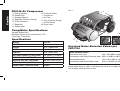
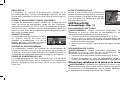
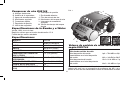
A. Sliding Handles
B. Handle Grip
C. Storage Support
D. Regulator Pressure Gauge
E. Quick Connects
F. Regulator
G. Safety Valve
Pump/Motor Specifi cations
Voltage: Single 120V
Minimum branch circuit requirement: 15 A
Fuse Type: Time delay
Specifi cations
MODEL
D55146
WEIGHT
83 lbs. (39.92 kg)
HEIGHT
15.5" (1060.5mm)
WIDTH
23.0" (482.6 mm)
LENGTH
33.0" (539.8 mm)
AIR TANK CAPACITY (GALLONS)
4.5 Gallon (17.0 liters)
APPROX CUT-IN PRESSURE
160 PSI (827.3 kPa)
APPROX. CUT-OUT PRESSURE
200 PSI (1034.2 kPa)
SCFM @ 90 PSI (620.5 kPa)
5.2
NOISE LEVEL (PER ISO 3744)
78 dBA
D55146 Air Compressor
H. Pressure Switch
I. Cord Wrap
J. Air Filter
K. Tank Pressure Gauge
L. On/Off Switch
M. Drain Valve
FIG. 1
G
E
B
A
F
H
L
I
D
K
C
J
M
Declared Noise Emission Values per
ISO3744
Noise Emission Values
Sound Pressure Level: LpA = 78.0 dBA re 20μPA
Uncertainty in the Sound Pressure Level: KpA = 3.0 dBA re 20μPA
Sound Power Level: LwA = 91.0 dBA re 1 pw
Uncertainty in the Sound Power Level: KwA = 3.0 dBA re 1 pw
The sum of the emission value and the uncertainty is the limit
below which there is a 95% confidence the value of a single tool
will lie below when the tool is new.

3
English
Defi nitions: Safety Guidelines
The definitions below describe the level of severity
for each signal word. Please read the manual and
pay attention to these symbols.
DANGER: Indicates an imminently hazardous
situation which, if not avoided, will result in death
or serious injury.
WARNING: Indicates a potentially hazardous
situation which, if not avoided, could result in death
or serious injury.
CAUTION: Indicates a potentially hazardous
situation which, if not avoided, may result in minor
or moderate injury.
CAUTION: Used without the safety alert symbol
indicates a potentially hazardous situation which, if
not avoided, may result in property damage.
IF YOU HAVE ANY QUESTIONS OR COMMENTS ABOUT
THIS OR ANY D
E
WALT TOOL, CALL US TOLL FREE AT:
1-800-4-D
E
WALT (1-800-433-9258)
Important Safety Instructions
Important Safety Instructions
WARNING: Do not operate this unit until you read and understand
this instruction manual for safety, operation and maintenance
instructions.
WARNING: Some dust created by power sanding, sawing, grind-
ing, drilling, and other construction activities contains chemicals
known to the State of California to cause cancer, birth defects or other
reproductive harm. Some example of these chemicals are:
• lead from lead-based paints
• crystalline silica from bricks and cement and other masonry
products
• arsenic and chromium from chemically-treated lumber
Your risk from these exposures varies, depending on how often
you do this type of work. To reduce your exposure to these chemi-
cals: work in a well ventilated area, and work with approved safety
equipment, al ways wear OSHA/MSHA/NIOSH approved, properly
fit ting face mask or res pi ra tor when us ing such tools.
When using air tools, basic safety precautions should always be fol-
lowed to reduce the risk of of personal injury.
WARNING: This product contains chemicals, including lead, known
to the State of California to cause cancer, and birth defects or other
reproductive harm. Wash hands after handling.
SAVE THESE INSTRUCTION
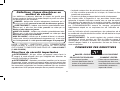
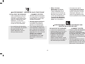
DANGER: RISK OF EXPLOSION OR FIRE
WHAT CAN HAPPEN HOW TO PREVENT IT
• It is normal for electrical
contacts within the motor
and pressure switch to
spark.
• Always operate the compres-
sor in a well ventilated area
free of combustible materials,
gasoline, or solvent vapors.
• If electrical sparks from
compressor come into con-
tact with flammable vapors,
they may ignite, causing fire
or explosion.
• If spraying flammable materi-
als, locate compressor at
least 20 feet (6.1 m) away
from spray area. An addi-
tional length of hose may be
required.
• Store flammable materials in
a secure location away from
compressor.

4
English
• Restricting any of the com-
pressor ventilation openings
will cause serious overheat-
ing and could cause fire.
• Never place objects against
or on top of compressor
pump.
• Operate compressor in
an open area at least 12"
(30.5 cm) away from any
wall or obstruction that would
restrict the flow of fresh air to
the ventilation openings.
• Operate compressor in a
clean, dry well ventilated area.
Do not operate unit indoors or
in any confined area.
• Unattended operation of
this product could result in
personal injury or property
damage. To reduce the risk
of fire, do not allow the
compressor to operate unat-
tended.
• Always remain in attendance
with the product when it is
operating.
• Always turn off and unplug
unit when not in use.
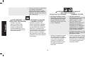
DANGER: RISK TO BREATHING (ASPHYXIATION)
WHAT CAN HAPPEN HOW TO PREVENT IT
• The compressed air directly
from your compressor is not
safe for breathing. The air
stream may contain carbon
monoxide, toxic vapors,
or solid particles from the
air tank. Breathing these
contaminant's can cause
serious injury or death.
• Air obtained directly from the
compressor should never
be used to supply air for
human consumption. In order
to use air produced by this
compressor for breathing,
suitable filters and in-line
safety equipment must be
properly installed. In-line
filters and safety equipment
used in conjunction with the
compressor must be capable
of treating air to all applicable
local and federal codes prior to
human consumption.
• Sprayed materials such as
paint, paint solvents, paint
remover, insecticides, weed
killers, may contain harmful
vapors and poisons.
• Work in an area with good
cross ventilation. Read and
follow the safety instructions
provided on the label or safety
data sheets for the materials
you are spraying. Always use
certified safety equipment:
OSHA/MSHA/NIOSH
respiratory protection designed
for use with your specific
application.

5
English
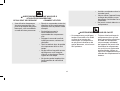
WARNING: RISK OF BURSTING
Air Tank: The air tank on your Air Compressor is designed and may
be UM coded (for units with air tanks greater than 6 inch diameter)
according to ASME Section VIII, Div. 1 rules. All pressure vessels
should be inspected once every two years. To find your state pressure
vessels inspector, look under the Division of Labor and Industries in
the government section of a phone book or call 1-800-4-D
EWALT for
assistance.
The following conditions could lead to a weakening of the air tank,
and result in a violent air tank explosion:
WHAT CAN HAPPEN HOW TO PREVENT IT
• Failure to properly drain
condensed water from
air tank, causing rust and
thinning of the steel air tank.
• Drain air tank daily or after
each use. If air tank develops
a leak, replace it immediately
with a new air tank or replace
the entire compressor.
• Modifications or attempted
repairs to the air tank.
• Never drill into, weld, or make
any modifications to the air
tank or its attachments. Never
attempt to repair a damaged or
leaking air tank. Replace with a
new air tank.
• Unauthorized modifications
to the safety valve or any
other components which
control air tank pressure.
• The air tank is designed
to withstand specific
operating pressures. Never
make adjustments or parts
substitutions to alter the factory
set operating pressures.
Attachments & accessories:
• Exceeding the pressure
rating of air tools, spray guns,
air operated accessories,
tires, and other inflatables
can cause them to explode
or fly apart, and could result
in serious injury.
• Follow the equipment manu-
facturers recommendation
and never exceed the maxi-
mum allowable pressure rat-
ing of attachments. Never use
compressor to inflate small
low pressure objects such
as children’s toys, footballs,
basketballs, etc.
Tires:
• Over inflation of tires could
result in serious injury and
property damage.
• Use a tire pressure gauge to
check the tires pressure before
each use and while inflating
tires; see the tire sidewall for
the correct tire pressure.
NOTE: Air tanks, compressors and
similar equipment used to inflate
tires can fill small tires similar to
these very rapidly. Adjust pressure
regulator on air supply to no more
than the rating of the tire pressure.
Add air in small increments and
frequently use the tire gauge to
prevent over inflation.

6
English
WARNING: RISK OF ELECTRICAL SHOCK
WHAT CAN HAPPEN HOW TO PREVENT IT
• Your air compressor is
powered by electricity.
Like any other electrically
powered device, If it is not
used properly it may cause
electric shock.
• Never operate the
compressor outdoors when it
is raining or in wet conditions.
• Never operate compressor
with protective covers
removed or damaged.
• Repairs attempted by
unqualified personnel can
result in serious injury or
death by electrocution.
• Any electrical wiring or
repairs required on this
product should be performed
by a D
EWALT factory
service center or a D
EWALT
authorized service center in
accordance with national and
local electrical codes.
• Electrical Grounding:
Failure to provide adequate
grounding to this product
could result in serious injury
or death from electrocution.
See Grounding
Instructions under
Installation.
• Make certain that the
electrical circuit to which the
compressor is connected
provides proper electrical
grounding, correct voltage
and adequate fuse protection.
WARNING: RISK FROM FLYING OBJECTS
WHAT CAN HAPPEN HOW TO PREVENT IT
• The compressed air stream
can cause soft tissue
damage to exposed skin and
can propel dirt, chips, loose
particles, and small objects
at high speed, resulting in
property damage or personal
injury.
• Always wear certified safety
equipment: ANSI Z87.1 eye
protection (CAN/CSA Z94.3)
with side shields when using
the compressor.
• Never point any nozzle or
sprayer toward any part of
the body or at other people or
animals.
• Always turn the compressor off
and bleed pressure from the
air hose and air tank before
attempting maintenance,
attaching tools or accessories.

7
English
WARNING: RISK OF HOT SURFACES
WHAT CAN HAPPEN HOW TO PREVENT IT
• Touching exposed metal
such as the compressor
head, engine head, engine
exhaust or outlet tubes, can
result in serious burns.
• Never touch any exposed
metal parts on compressor
during or immediately after
operation. Compressor will
remain hot for several minutes
after operation.
• Do not reach around
protective shrouds or attempt
maintenance until unit has
been allowed to cool.
WARNING: RISK FROM MOVING PARTS
WHAT CAN HAPPEN HOW TO PREVENT IT
• Moving parts such as the
pulley, flywheel, and belt can
cause serious injury if they
come into contact with you or
your clothing.
• Never operate the compressor
with guards or covers which
are damaged or removed.
• Keep your hair, clothing, and
gloves away from moving
parts. Loose clothes, jewelry,
or long hair can be caught in
moving parts.
• Air vents may cover moving
parts and should be avoided
as well.
• Attempting to operate
compressor with damaged or
missing parts or attempting
to repair compressor with
protective shrouds removed
can expose you to moving
parts and can result in
serious injury.
• Any repairs required on this
product should be performed
by a D
EWALT factory
service center or a D
EWALT
authorized service center.
WARNING: RISK OF UNSAFE OPERATION
WHAT CAN HAPPEN HOW TO PREVENT IT
• Unsafe op er a tion of your air
compressor could lead to se ri-
ous in ju ry or death to you or
others.
• Review and understand all
instructions and warnings in
this manual.
• Be come fa mil iar with the
op eration and con trols of the
air compressor.
• Keep operating area clear
of all persons, pets, and
obstacles.
• Keep chil dren away from the
air compressor at all times.
• Do not operate the product
when fatigued or under the
influence of alcohol or drugs.
Stay alert at all times.
• Never defeat the safety fea-
tures of this prod uct.

8
English
CAUTION: RISK FROM NOISE
WHAT CAN HAPPEN HOW TO PREVENT IT
• Under some conditions and
duration of use, noise from
this product may contribute
to hearing loss.
• Always wear certified safety
equipment: ANSI S12.6
(S3.19) hearing protection.
SAVE THESE INSTRUCTIONS
FOR FUTURE USE
• Equip area of operation with
a fire extinguisher.
• Do not op er ate machine with
missing, broken, or un au tho-
rized parts.
• Never stand on the
compressor.
WARNING: RISK OF FALLING
WHAT CAN HAPPEN HOW TO PREVENT IT
• A portable compressor
can fall from a table,
workbench, or roof causing
damage to the compressor
and could result in serious
injury or death to the
operator.
• Always operate compressor
in a stable secure position to
prevent accidental movement
of the unit. Never operate
compressor on a roof or
other elevated position. Use
additional air hose to reach
high locations.
WARNING: RISK OF
INJURY FROM LIFTING
WHAT CAN HAPPEN HOW TO PREVENT IT
• Serious injury can result
from attempting to lift too
heavy an object.
• The compressor is too
heavyto be lifted by one
person. Obtain assistance
from others before lifting.

9
English
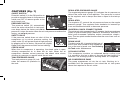
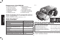
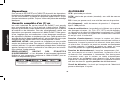
FEATURES (Fig. 1)
ON/OFF SWITCH
Place this switch (L) in the ON position to
H
L
provide automatic power to the pressure
switch and OFF to remove power at the
end of each use.
PRESSURE SWITCH
The pressure switch (H) automatically
starts the motor when the air tank pres-
sure drops below the factory set cut-in
pressure. It stops the motor when the air tank pressure reaches the
factory set cut-out pressure.
SAFETY VALVE
If the pressure switch does not shut off the air
G
compressor at its cut-out pressure setting, the
safety valve (G) will protect against high pressure
by popping out at its factory set pressure (slightly
higher than the pressure switch cut-out setting).
CHECK VALVE
When the air compressor is operating, the check valve is open,
allowing compressed air to enter the air tank. When the air
compressor reaches cut-out pressure, the check valve closes,
allowing air pressure to remain inside the air tank.
TANK PRESSURE GAUGE
The tank pressure gauge (K) indi-
E
F
D
K
cates the reserve air pressure in
the tank.
REGULATED
PRESSURE GAUGE
The regulated pressure gauge (D) indicates the air pressure avail-
able at the outlet side of the regulator. This pressure is controlled
by the regulator and is always less than or equal to the tank pres-
sure.
REGULATOR
The regulator (F) controls the air pressure shown on the regulated
pressure gauge. Turn regulator knob clockwise to increase pres-
sure and counterclockwise to decrease pressure.
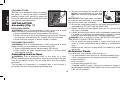
UNIVERSAL QUICK CONNECT BODIES
The universal quick connect body (E) accepts the three most popular
styles of quick connect plugs: Industrial, automotive, and ARO. One
hand push-to-connect operation makes connections simple and
easy. The two quick connect bodies allow the use of two tools at the
same time.
DRAIN VALVE
The drain valve (M) is located at the base of
M
the air tank and is used to drain condensa-
tion at the end of each use.
See Draining
Air Tank under Maintenance.
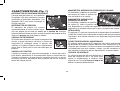
COOLING SYSTEM
This compressor contains an advanced design cooling system.
It is normal for this fan to blow air through the vent holes in large
amounts. The cooling system is working when air is expelled.
AIR COMPRESSOR PUMP
The pump compresses air into the air tank. Working air is not
available until the compressor has raised the air tank pressure
above that required at the air outlet.

10
English
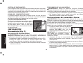
AIR INTAKE FILTER
The filter (J) is designed to clean air entering
J
the pump. To ensure the pump continually
receives a clean, cool, and dry air supply the
filter must always be clean and the filter intake
must be free from obstructions.
INSTALLATION
Assembly (Fig. 1)
INSTALLING HOSES
WARNING: Risk of unsafe operation. Firmly grasp hose in hand
when installing or disconnecting to prevent hose whip.
1. Ensure regulated pressure gauge reads 0 PSI (0 kPa).
2. Grasp the hose at the quick connect plug and push the plug
into the quick connect body (E). Coupler will snap into place.
3. Grasp the hose and pull to ensure coupler is seated.
DISCONNECTING HOSES
WARNING: Risk of unsafe operation. Firmly grasp hose in hand
when installing or disconnecting to prevent hose whip.
1. Ensure regulated pressure gauge reads 0 PSI (0 kPa).
2. Push coupler on quick connect body back to release quick
connect plug on hose.
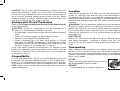
Grounding Instructions
WARNING: Risk of electrical shock. In the event of a short
circuit, grounding reduces the risk of shock by providing an escape
wire for the electric current. This air compressor must be properly
grounded.
The portable air compressor is equipped with a cord having a
grounding wire with an appropriate grounding plug.
1. The cord set and plug (R) with this unit
S
R
T
contains a grounding pin (S). This plug
MUST be used with a grounded outlet
(T).
IMPORTANT: The outlet being used must
be installed and grounded in accordance
with all local codes and ordinances.
2. Ensure the outlet being used has the same configuration as the
grounded plug. DO NOT USE AN ADAPTER.
3. Inspect the plug and cord before each use. Do not use if there
are signs of damage.
4. If these grounding instructions are not completely understood, or
if in doubt as to whether the compressor is properly grounded,
have the installation checked by a qualified electrician.
DANGER: Risk of electrical shock. IMPROPER GROUNDING
CAN RESULT IN ELECTRICAL SHOCK.
• Do not modify the plug provided. If it does not fit the available
outlet, a correct outlet should be installed by a qualified electri-
cian.
• Repairs to the cord set or plug MUST be made by a qualified
electrician.
Extension Cords
If an extension cord must be used, be sure it is:
• a 3-wire extension cord that has a 3-blade grounding plug, and
a 3-slot receptacle that will accept the plug on the product
• in good condition
• plug is not worn
• no longer than 50 feet (15,2 m)
• 12 gauge (AWG) or larger. (Wire size increases as gauge num-
ber decreases. 10 AWG and 8 AWG may also be used. DO NOT
USE 14 OR 16 AWG.)

11
English
CAUTION: The use of an undersized extension cord will cause volt-
age to drop resulting in power loss to the motor and overheating.
Instead of using an extension cord, increase the working reach of
the air hose by attaching another length of hose to its end. Attach
additional lengths of hose as needed.
Always use a minimum 3/8"
(9.5 mm) or greater air hose rated at 300 PSI.
Voltage and Circuit Protection
Refer to the Voltage and Minimum Branch Circuit Requirements
under Specifications.
CAUTION: Certain air compressors can be operated on a
15 amp circuit if the following conditions are met.
• Voltage supply to circuit must comply with the National Electrical
Code.
• Circuit is not used to supply any other electrical needs.
• Extension cords comply with specifications.
• Circuit is equipped with a 15 amp circuit breaker or 15 amp
time delay fuse. NOTE: If compressor is connected to a circuit
protected by fuses, use only time delay fuses. Time delay fuses
should be marked “D” in Canada and “T” in the U.S.
If any of the above conditions cannot be met, or if operation of the
compressor repeatedly causes interruption of the power, it may be
necessary to operate it from a 20 amp circuit. It is not necessary
to change the cord set.
Compatibility
Air tools and accessories that are run off the compressor must be
compatible with petroleum-based products. If you suspect that a
material is not compatible with petroleum products, an air line filter
for removal of moisture and oil vapor in compressed air is required.
NOTE: Always use an air line filter to remove moisture and oil vapor
when spraying paint.
Location
Place the air compressor in a clean, dry and well ventilated area
at least 12" (30.5 cm) away from the wall or other obstructions that
will interfere with the flow of air. Keep the compressor away from
areas that have dirt and/or volatile fumes in the atmosphere. These
impurities may clog the intake filter and valves, causing inefficient
operation.
WARNING: The air compressor pump and shroud are designed
to allow for proper cooling. The ventilation openings on the com-
pressor are necessary to maintain proper operating temperature.
Do not place rags or other containers on or near these openings.
Place the air compressor on a flat surface resting on the wheels
and rubber foot.
ELECTRICAL
Refer to all safety instructions before using unit. Observe extension
cord safety instructions, if necessary. Always move the On/Off
switch (L) to the OFF position before removing the plug from the
outlet.
Transporting
When transporting the compressor in a vehicle, trailer, etc. ensure
that the air tank is drained and the unit is secured and placed on a
flat horizontal surface. Use care when driving so to avoid tipping the
unit over in the vehicle. Damage can occur to the unit or surrounding
items if unit is tipped.
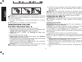
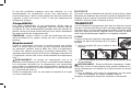
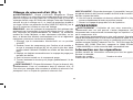
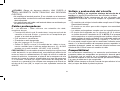
LIFTING
Always use two people when lifting and lift from
B
C
the recommended lift points B and C.
MOVING
1. Grasp handle (B) to support compressor.

12
English
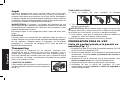
B
A
A
B
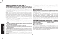
2. Pull handle (A) until fully extended (lock position).
WARNING: Risk of unsafe operation. Ensure proper footing and
use caution when rolling compressor so that unit does not tip or
cause loss of balance.
3. To move, roll compressor on tires using handle (A) as shown
above.
Store compressor in a vertical or horzitional position.
PREPARATION FOR USE
Pre-Start Checklist (Fig. 1)
1.
Ensure the On/Off switch (L) is in the OFF position.
2.
Plug the power cord into the correct branch circuit receptacle.
See
Voltage and Circuit Protection under Installation.
3. Ensure air tank is drained, see Draining Air Tank under
Maintenance.
4. Ensure the drain valve is closed.
5. Ensure safety valve (G) is functioning properly, see Checking
Safety Valve under Maintenance.
6. Turn regulator knob (F) counterclockwise until fully closed. Ensure
regulated pressure gauge reads 0 PSI (0 kPa).
7. Attach hose and accessories. NOTE: Always use a minimum
3/8" or greater air hose rated at 300 PSI.
WARNING: Risk of unsafe operation. Firmly grasp hose in hand
when installing or disconnecting to prevent hose whip.
8. Ensure all covers and labels are in place, legible (for labels) and
securely mounted. Do not use compressor until all items have
been verified.
WARNING: Risk of bursting. Too much air pressure causes a
hazardous risk of bursting. Check the manufacturer’s maximum
pressure rating for air tools and accessories. The regulator outlet
pressure must never exceed the maximum pressure rating.
Initial Set-up
(Fig. 1)
WARNING: Do not operate this unit until you read and understand
this instruction manual for safety, operation and maintenance
instructions.
BREAK-IN PROCEDURE
CAUTION: Risk of unsafe operation. Be sure compressor is in
horizontal position before operating.
CAUTION:
Risk of property damage. Serious damage may result if
the following break-in instructions are not closely followed.
This procedure is required before the air compressor is put into
service for the first time and when the compressor pump/motor has
been replaced.
1. Ensure the On/Off switch (L) is in the OFF position.
NOTE: If hose is not connected to Quick Connect body, pull coupler
back until it clicks to prevent air from escaping through the quick
connect.
2.
Plug the power cord into the correct branch circuit receptacle.
See
Voltage and Circuit Protection under Installation.
3. Open the drain valve (counterclockwise) fully to permit air to
escape and prevent air pressure build up in the air tank during
the break-in period.
4. Move the On/Off switch to the ON position. The compressor will
start.
B

13
English
5. Run the compressor for 15 minutes.
6. After 15 minutes, close the drain valve by turning clockwise.
The tank will fill to cut-out pressure and the motor will stop.
7. Compressed air will be available until it is used or bled off.
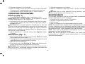
OPERATING PROCEDURES
Start-up (Fig. 1)
1. Follow Pre-Start Checklist under Preparation for Use.
CAUTION: Risk of unsafe operation. Do not operate in upright
position. Upright position is for storage only.
2. Move the On/Off switch to the ON position an
d allow tank pres-
sure to build. Motor will stop when tank pressure reaches
cut-out pressure.
CAUTION: Risk of unsafe operation. Compressed air from the
unit may contain wa ter condensation and oil mist. Do not spray un fil-
tered air at an item that could be damaged by moisture. Some air
op er ated tools or de vic es may require filtered air. Read the in struc-
tions for the air tool or device.
3. Adjust regulator (F) to desired setting. See Regulator under
Features.
Shut-down (Fig. 1)
1. Move On/Off switch (L) to the OFF position. NOTE: If finished
using compressor, follow Steps 2 – 6.
2. Turn regulator knob (F) counterclockwise until fully closed. Ensure
regulated pressure gauge reads 0 PSI (0 kPa).
3. Remove hose and accessory.
4. Drain the air tank,
see Draining Air Tank under Maintenance
.
Ensure air tank pressure gauge reads 0 PSI (0 kPa).
WARNING: Risk of bursting. Drain air tank daily. Water will con-
dense in air tank. If not drained, water will corrode and weaken the
air tank causing a risk of air tank rupture.
5. Allow the compressor to cool down.
6. Wipe air compressor clean and store in a safe, non-freezing
area.
CAUTION: Risk of unsafe operation. Do not operate in upright
position. Upright position is for storage only.
MAINTENANCE
The following procedures must be followed when maintenance or
service is performed on the air compressor.
1. Ensure On/Off switch is in the OFF position.
2. Remove air compressor plug from outlet.
3. Drain air tank.
4. Allow air compressor to cool down before starting service.
NOTE: All compressed air systems contain maintenance parts (e.g.,
oil, filters, separators) that are periodically replaced. These used parts
may contain substances that are regulated and must be disposed of in
accordance with local, state, and federal laws and regulations.
NOTE: Take note of the positions and locations of parts during
disassembly to make reassembly easier.
NOTE: Any service operations not included in this section should
be performed by a D
E
WALT factory service center or a D
E
WALT
authorized service center.

14
English
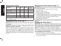
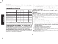
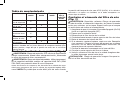
Maintenance Chart
Procedure Daily Weekly Monthly 1 year or
200 Hours
Check safety valve
X
Inspect air filter
+
X
Drain air tank
X
Check for unusual noise/
vibration
X
Check for air leaks*
X
Clean compressor exterior
X
* To check for air leaks apply a solution of soapy water around joints.
While compressor is pumping to pressure and after pressure cuts out,
look for air bubbles to form.
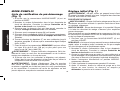
Checking Safety Valve (Fig. 1)
WARNING: Risk of bursting. If the safety valve does not work
properly, over-pressurization may occur, causing air tank rupture or
an explosion.
WARNING: Risk from flying objects. Always wear certified safety
equipment: ANSI Z87.1 eye protection (CAN/CSA Z94.3) with side
shields when using the compressor.
Before starting compressor, pull the ring on the safety valve to
make sure that the safety valve operates freely. Before starting
compressor, pull the ring on the safety valve to make sure that the
safety valve operates freely. NOTE: Ring may be difficult to pull
when air tank pressure is at 0 PSI (0 kPa). If the valve is stuck or
does not operate smoothly, it must be replaced with the same type
of valve.
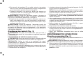
Checking Air Filter Element (Fig. 1)
WARNING: Hot surfaces. Risk of burn. outlet tube, pump head,
and surrounding parts are very hot, do not touch. Allow compressor
to cool prior to servicing.
1. Ensure the On/Off switch (L) is in the OFF position.
2. Allow unit to cool.
3. Remove air filter from unit.
4. Carefully pry filter top from base.
5. Remove element from filter base.
6. If element needs cleaning, blow out with air. Replace if needed.
Purchase replacement parts from your local dealer or authorized
service center. Always use identical replacement parts.
7. Place element back in filter base.
8. Snap filter top to filter base.
9. Reassemble air filter to unit. Ensure exhaust outlet points down.
CAUTION: Risk of unsafe operation. Do not operate without air
inlet filter
Draining Air Tank (Fig. 1)
WARNING: Risk of unsafe operation. Risk from noise. Air tanks
contain high pressure air. Keep face and other body parts away from
outlet of drain. Use safety glasses [ANSI Z87.1 (CAN/CSA Z94.3)]
when draining as debris can be kicked up into face. Use ear protection
[ANSI S12.6 (S3.19)] as air flow noise is loud when draining.
NOTE: All compressed air systems generate condensate that
accumulates in any drain point (e.g. tanks, filter, aftercoolers, dryers).
This condensate contains lubricating oil and/or substances which
may be regulated and must be disposed of in accordance with local,
state, and federal laws and regulations.
1. Ensure On/Off switch is in the OFF position.
2
. Lift front of compressor into an inclined position so drain valve
(M) is at the lowest point (this will assist in removing moisture,
dirt, etc. from air tanks).

15
English
3. Place a suitable container under the drain valve to catch
discharge.
4. Grasp knob on drain valve.
5. Slowly rotate knob to gradually bleed air from air tank.
WARNING: Risk of bursting. Drain air tank daily. Water will con-
dense in air tank. If not drained, water will corrode and weaken the
air tank causing a risk of air tank rupture.
CAUTION: Risk of property damage. Drain water from air tank may
contain oil and rust, which can cause stains.
6. When air tank pressure gauge reads 10 PSI (68,9 kPa), rotate
valve to the fully open position.
7. Close drain valve when finished.
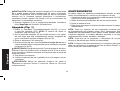
ACCESSORIES
WARNING: The use of any other accessory not recommended for
use with this tool could be hazardous. Use only accessories rated
equal to or higher than the rating of the air compressor.
Recommended accessories for use with your tool are available
for purchase from your local dealer or authorized service center.
If you need assistance in locating any accessory for your tool,
please contact D
E
WALT Industrial Tool Co., 701 East Joppa Road,
Baltimore, MD 21286, call 1-800-4-D
E
WALT (1-800-433-9258) or visit
our website www.dewalt.com.
SERVICE INFORMATION
Please have the following information available for all service calls:
Model Number ____________ Serial Number _________________
Date and Place of Purchase ______________________________
Repairs
To assure product SAFETY and RELIABILITY, repairs, maintenance
and adjustment should be performed by a D
E
WALT factory service
center, a D
E
WALT authorized service center or other qualified
service personnel. Always use identical replacement parts.
Full One Year Warranty
DEWALT heavy duty industrial tools are warranted for one year from
date of purchase. We will repair, without charge, any defects due
to faulty materials or workmanship. For warranty repair information,
call 1-800-4-D
E
WALT. This warranty does not apply to accessories
or damage caused where repairs have been made or attempted by
others. This warranty gives you specific legal rights and you may
have other rights which vary in certain states or provinces.
LATIN AMERICA: This warranty does not apply to products sold
in Latin America. For products sold in Latin America, see country
specific warranty information contained either in the packaging, call
the local company or see website for warranty information.
FREE WARNING LABEL REPLACEMENT: If your warning labels
become illegible or are missing, call 1-800-4-D
E
WALT for a free
replacement.
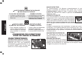
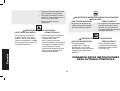
DO NOT OPERATE IN UPRIGHT
POSITION. UPRIGHT POSITION
IS FOR STORAGE ONLY.
NO OPERE LA HERRAMIENTA EN
POSICIÓN VERTICAL. SÓLO
ALMACENE EN ESTA POSICIÓN.
NE PAS FAIRE FONCTIONNER EN POSITION
VERTICALE. LA POSITION VERTICALE EST
RÉSERVÉE AU STOCKAGE UNIQUEMENT.
A18907

16
English
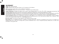
GLOSSARY
CFM: Cubic feet per minute.
SCFM: Standard cubic feet per minute; a unit of measure of air delivery.
PSI: Pounds per square inch; a unit of measure of pressure.
kPa (kilopascal): Metric pressure measurement. 1 kilopascal equal 1000 pascals.
Code Certification: Products that bear one or more of the following marks: UL, CUL, ETL, CETL, have been evaluated by OSHA
certified independent safety laboratories and meet the applicable Underwriters Laboratories Standards for Safety.
Cut-In Pressure: While the motor is off, air tank pressure drops when accessory is used. When the tank pressure drops to a certain low
level the motor will restart automatically. The low pressure at which the motor automatically restarts is called cut-in pressure.
Cut-Out Pressure: When an air compressor is turned on and begins to run, air pressure in the air tank begins to build. It builds to a
certain high pressure before the motor automatically shuts off, protecting your air tank from pressure higher than its capacity. The high
pressure at which the motor shuts off is called cut-out pressure.
Branch Circuit: The circuit carrying electricity from electrical panel to outlet.
Duty Cycle: This air compressor pump is capable of running continuously. However, to prolong the life of your air compressor, it is
recommended that a 50%-75% average duty cycle be maintained; that is, the air compressor pump should not run more than 30-
45 minutes in any given hour.

17
English
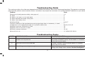
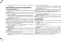
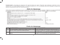
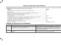
Troubleshooting Guide
This section provides a list of the more frequently encountered malfunctions, their causes and corrective actions. The operator or maintenance
personnel can perform some corrective actions, and others may require the assistance of a qualified D
EWALT technician or your dealer.
Problem Code
Excessive air tank pressure-safety valve pops off ......................................................................1,2
Air leaks ....................................................................................................................................3
Air leaks in air tank or at air tank welds ....................................................................................4
Air leaks between head and valve plate ....................................................................................5
Air leaks from safety valve .........................................................................................................6
Knocking Noise ..........................................................................................................................6,16,17
Pressure reading on the regulated pressure gauge drops when an accessory is used ...........7
Compressor is not supplying enough air to operate accessories..............................................8,9,10,11,12,15
Regulator knob has continuous air leak ....................................................................................13
Regulator will not shut off air outlet ...........................................................................................13
Moisture in pump crankcase ......................................................................................................14,18
Motor will not run .......................................................................................................................11,19,20,21,22,23,24
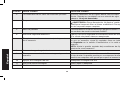
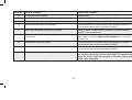
Troubleshooting Codes
CODE POSSIBLE CAUSE POSSIBLE SOLUTION
1 Pressure switch does not shut off motor when compressor
reaches cut-out pressure
Set the On/Off switch to OFF, if the unit does not shut
off contact a D
E
WALT factory service center or a D
E
WALT
authorized service center.
2
Pressure switch cut-out too high
Contact a D
E
WALT factory service center or a D
E
WALT
authorized service center.
3
Tube fittings are not tight enough Tighten fittings where air can be heard escaping. Check
fittings with soapy water solution. Do Not Overtighten.

18
English
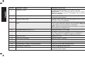
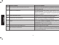
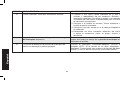
CODE POSSIBLE CAUSE POSSIBLE SOLUTION
4 Defective air tank Air tank must be replaced. Do not repair the leak.
WARNING: Risk of bursting. Do not drill into, weld or
otherwise modify air tank or it will weaken. The air tank can
rupture or explode.
5 Leaking seals Contact a D
E
WALT factory service center or a D
E
WALT
authorized service center.
6 Defective safety valve Operate safety valve manually by pulling on ring. If valve
still leaks, it must be replaced.
7
Regulator is not adjusted correctly for accessory being
used
It is normal for some pressure drop to occur when an acces-
sory is used, adjust the regulator as instructed in Regulator
under Features if pressure drop is excessive.
NOTE: Adjust the regulated pressure under flow conditions
while accessory is being used.
8 Prolonged excessive use of air Decrease amount of air usage.
9 Compressor is not large enough for accessory Check the accessory air requirement. If it is higher than
the CFM or pressure supplied by your air compressor, a
larger compressor is needed to operate accessory.
10 Hole in air hose Replace air hose.
11 Check valve restricted Remove, clean or replace.
12 Air leaks Tighten fittings.
13 Regulator is damaged Replace.
14 Unit operating in damp or humid conditions Move unit to a dry well ventilated area
15 Restricted air intake filter Clean or replace air intake filter
16
Carbon build-up in pump. Contact a D
E
WALT factory service center or a D
E
WALT
authorized service center.

19
English
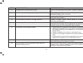
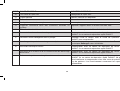
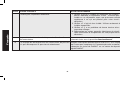
CODE POSSIBLE CAUSE POSSIBLE SOLUTION
17
Detergent type oil being used in pump Drain oil and refill pump with D
E
WALT synthetic compressor
oil.
18
Extension cord is wrong length or gauge Check for proper gauge wire and cord length. See
Extension Cords under Installation.
19
Loose electrical connections
Contact a D
E
WALT factory service center or a D
E
WALT
authorized service center.
20
Possible defective motor or starting capacitor
Contact a D
E
WALT factory service center or a D
E
WALT
authorized service center.
21
Paint spray on internal motor parts Contact a D
E
WALT factory service center or a D
E
WALT
authorized service center. Do not operate the compressor in
the paint spray area. See flammable vapor warning.
22
Fuse blown, circuit breaker tripped 1. Check fuse box for blown fuse and replace as necessary.
Reset circuit breaker. Do not use a fuse or circuit breaker
with higher rating than that specified for your particular
branch circuit.
2. Check for proper fuse. Use only a time delay fuse.
3. Check for low voltage conditions and/or proper extension
cord.
4. Disconnect the other electrical appliances from circuit or
operate the compressor on its own branch circuit.
23
Tank pressure exceeds pressure switch cut-in pressure Motor will start automatically when tank pressure drops
below cut-in pressure of pressure switch.
24
Pressure release valve on pressure switch has not
unloaded head pressure
Set the On/Off switch to OFF. If the valve does not open,
replace switch. Contact a D
E
WALT factory service center or
a D
E
WALT authorized service center.
Page is loading ...
Page is loading ...
Page is loading ...
Page is loading ...
Page is loading ...
Page is loading ...
Page is loading ...
Page is loading ...
Page is loading ...
Page is loading ...
Page is loading ...
Page is loading ...
Page is loading ...
Page is loading ...
Page is loading ...
Page is loading ...
Page is loading ...
Page is loading ...
Page is loading ...
Page is loading ...
Page is loading ...
Page is loading ...
Page is loading ...
Page is loading ...
Page is loading ...
Page is loading ...
Page is loading ...
Page is loading ...
Page is loading ...
Page is loading ...
Page is loading ...
Page is loading ...
Page is loading ...
Page is loading ...
Page is loading ...
Page is loading ...
Page is loading ...
Page is loading ...
Page is loading ...
Page is loading ...
Page is loading ...
Page is loading ...
Page is loading ...
Page is loading ...

D
E
WALT Industrial Tool Co., 701 Joppa Road, Baltimore, MD 21286
(OCT06) Form No. A18765 D55146 Copyright © 2006 D
E
WALT
The following are trademarks for one or more D
E
WALT power tools: the yellow and black color scheme; the “D” shaped air intake grill; the
array of pyramids on the handgrip; the kit box configuration; and the array of lozenge-shaped humps on the surface of the tool.
-
 1
1
-
 2
2
-
 3
3
-
 4
4
-
 5
5
-
 6
6
-
 7
7
-
 8
8
-
 9
9
-
 10
10
-
 11
11
-
 12
12
-
 13
13
-
 14
14
-
 15
15
-
 16
16
-
 17
17
-
 18
18
-
 19
19
-
 20
20
-
 21
21
-
 22
22
-
 23
23
-
 24
24
-
 25
25
-
 26
26
-
 27
27
-
 28
28
-
 29
29
-
 30
30
-
 31
31
-
 32
32
-
 33
33
-
 34
34
-
 35
35
-
 36
36
-
 37
37
-
 38
38
-
 39
39
-
 40
40
-
 41
41
-
 42
42
-
 43
43
-
 44
44
-
 45
45
-
 46
46
-
 47
47
-
 48
48
-
 49
49
-
 50
50
-
 51
51
-
 52
52
-
 53
53
-
 54
54
-
 55
55
-
 56
56
-
 57
57
-
 58
58
-
 59
59
-
 60
60
-
 61
61
-
 62
62
-
 63
63
-
 64
64


DeWalt D55146 User manual
- Category
- Air compressors
- Type
- User manual
- This manual is also suitable for
Ask a question and I''ll find the answer in the document
Finding information in a document is now easier with AI
in other languages
- français: DeWalt D55146 Manuel utilisateur
- español: DeWalt D55146 Manual de usuario
Related papers
-
DeWalt DWFP55120 TYPE 1 Owner's manual
-
-
-
-
-
-
-
-
-
DeWalt D2002M-WK User manual
Other documents
-
Porter-Cable C2002 User manual
-
Craftsman 009-16957-000 Owner's manual
-
 Air Mate AM782HC4V User manual
-
Epson D55168 User manual
-
Porter-Cable C1010 User manual
-
-
Kobalt 3320447 User manual
-
MasterCraft 58-7922-8 User manual
-
-
