Shindaiwa EB8520 User manual
- Category
- Air blowers/dryers
- Type
- User manual
This manual is also suitable for

Part Number 68915-94310 Rev. 9/08
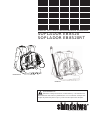
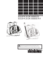
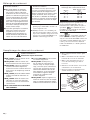
SHINDAIWA OWNER’S/OPERATOR’S MANUAL
EB8520 BLOWER
EB8520RT BLOWER
EB8520RT
EB8520
English
..........................1
Español
................... SP_1
Francais
.................. FR_1
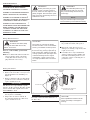
WARNING!
Minimize the risk of injury to yourself and others! Read this manual
and familiarize yourself with the contents. Always wear eye and hearing
protection when operating this unit.

2
WARNING!
The engine exhaust from this
unit contains chemicals known to the
State of California to cause cancer,
birth defects or other reproductive
harm.
IMPORTANT!
The operational procedures described in this manual are intended to help you get the most from this unit and also to protect you and others
from harm. These procedures are general guidelines only, and are not intended to replace any safety rules/laws that may be in force in your
area. If you have any questions regarding your EB8520 blower, or if you do not understand something in this manual, your Shindaiwa dealer
will be glad to assist you. For additional information, you may also contact Shindaiwa Inc. at the address printed on the back of this manual.
Introduction
CAUTION!
This blower is equipped with a spark-
arresting mufer! Never operate this
unit without both the mufer and
spark arrester installed and properly
functioning!
WARNING!
A statement preceded by the
triangular Attention Symbol and the
word “WARNING” indicates a poten-
tially hazardous situation which, if not
avoided, COULD result in death or seri-
ous injury.
Attention Statements
Safety and operation labels
CAUTION!
A statement preceded by the word
“CAUTION” contains information that
should be acted upon to avoid damag-
ing the unit.
NOTE:
A statement preceded by the word “NOTE”
contains information that is handy to know
and may make your job easier.
Contents
Attention Statements .................................2
General Safety Instructions
......................3
Unit Description
.........................................5
Specifications
..............................................5
Assembling the Blower
.............................6
Mixing Fuel
................................................8
Filling the Fuel Tank
.................................8
Starting and Stopping the Blower
............8
Adjusting Engine Idle Speed
.....................9
Using the Blower
.....................................10
Maintenance
.............................................11
Storage
......................................................13
Troubleshooting Guide
...........................14
Emission System Warranty
.....................17
PAGE PAGE PAGE
Throughout this manual are special “Atten-
tion Statements”.
The Shindaiwa EB8520 has been designed
and built to deliver superior performance
and reliability without compromise to qual-
ity, comfort, safety, or durability.
The information contained in this manual
describes units available at the time of produc-
tion. While every attempt has been made to
give you the very latest information about your
Shindaiwa EB8520 blower. There may be some
differences between your EB8520 blower and
what is described here.
IMPORTANT!
A statement preceded by the word
“IMPORTANT” is one that possesses spe-
cial significance.
IMPORTANT!
Before using this unit, consult local regu-
lations concerning noise restrictions and
hours of operation!
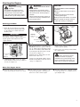
Read and follow this manual.
Failure to do so could result in
serious injury.
Wear eye and hearing protection
at all times during the operation
of this unit.
Keep hair and loose clothing clear
of the air inlet.
This unit is intended for outdoor
use only and should be used only
in well ventilated areas.
Shindaiwa Inc. reserves the right to make
changes in production without prior notice,
and without obligation to make alterations to
units previously manufactured.

IMPORTANT!
This engine is equipped with a heat sensor
in order to prevent the engine from over-
heating. If the sensor is activated, engine
speed will be reduced to 5,000 min
-1
(RPM).
If the engine speed is automatically reduced,
please cool the engine as described in the
section "Using the Blower".
IMPORTANT!
Safety and Operation Information Labels:
Make sure all information labels are
undamaged and readable. Immediately
replace damaged or missing information
labels. New labels are available from your
local authorized Shindaiwa dealer.
WARNING!
Metal surfaces of crank-
case may be hot! Always wear
gloves when handling this unit.
3
ALWAYS wear eye protection that
complies with ANSI Z 87.1 or your
applicable national standard to shield
against thrown objects.
NEVER run the engine indoors! Make
sure there is always good ventila-
tion. Fumes from engine exhaust can
cause serious injury or death.
ALWAYS stop the unit immediately if
it suddenly begins to vibrate or shake.
Inspect for broken, missing or improp-
erly installed parts.
ALWAYS keep the unit as clean as
practical. Keep it free of loose vegeta-
tion, mud, etc.
ALWAYS keep the handles clean.
ALWAYS disconnect the spark plug wire
before performing any maintenance work.
ALWAYS turn off the engine before
putting the unit down. When trans-
porting the unit in a vehicle, properly
secure it to prevent the unit from over
turning, fuel spillage and damage to
the unit.
NEVER insert any foreign objects into
the air intake or outlet opening of the
blower while in operation.
WARNING!
Never operate power
equipment of any kind if you are tired
or if you are under the inuence of
alcohol, drugs, medication or any
other substance that could affect your
ability or judgement.
WARNING!
Minimize the Risk of Fire
NEVER smoke or light res near the unit.
ALWAYS stop the engine and allow it to
cool before refueling. Avoid overlling and
wipe off any fuel that may have spilled.
ALWAYS inspect the unit for fuel leaks
before each use. During each rell,
check that no fuel leaks from around
the fuel cap and/or fuel tank.
If fuel leaks are evident, stop using the
unit immediately. Fuel leaks must be
repaired before using the unit.
ALWAYS move the unit to a place well
away from a fuel storage area or other
readily ammable materials before
starting the engine.
NEVER place ammable material
close to the engine mufer.
NEVER run the engine without the
spark arrester screen in place.
WARNING!
Never make unauthorized
modications or attachment installations.
Never use attachments not approved by
Shindaiwa for use on this unit.
Work Safely
Blowers operate at a very high speed and
can do serious damage or injury if they are
misused or abused. Never allow a person
without training or instruction to operate
your Blower!
Stay Alert
You must be physically and mentally fit to
operate this unit safely.
General Safety Instructions
WARNING!
Use Good Judgment
Safety Labels

15
m
4
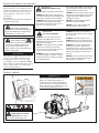
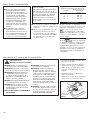
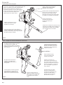
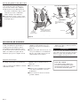
Be Aware of the Working Environment
Avoid long-term operation in very
hot or very cold weather.
Make sure bystanders or
observers outside the 15 m
(50-foot) “danger zone” wear
eye protection.
Reduce the risk of bystanders
being struck by ying debris.
Make sure no one is within 15
meters (50 feet)—that’s about 16
paces—of an operating blower.
15 METERS
Never operate the blower if any
component parts are damaged,
loose, or missing!
Debris sometimes collects on the
blower intake. Never clean out debris
from the blower while the engine is
running!
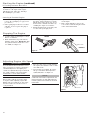
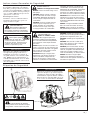
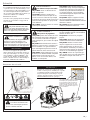
Figure 1
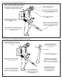
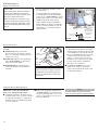
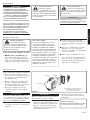
The Properly Equipped Operator
Wear a dust mask to
reduce the risk of inhalation
injuries.
Always wear eye protection such as a
face shield or goggles while operating
this unit. Never operate the blower
when visibility is poor.
Wear hearing protection
when operating this unit.
Wear close-tting clothing to protect legs and
arms. Gloves offer added protection and are
strongly recommended. Do not wear clothing
or jewelry that could get caught in machinery
or underbrush. Secure hair so it is above
shoulder level. NEVER wear shorts!
Wear appropriate footwear (non-skid
boots or shoes): do not wear open-toed
shoes or sandals. Never operate the unit
while barefoot!
Keep a proper footing and do
not overreach. Maintain your
balance at all times during
operation.
Always be aware of the strength and
direction of the blower discharge
stream. Never direct the blower
discharge stream toward people or
animals!
Be extremely careful of slippery
terrain, especially during rainy
weather. Never operate this
blower on a roof, ledge or ladder.
Be constantly alert for
objects and debris that
could be thrown from the air
blast and bounced from a
hard surface.
Do not direct the air blast
towards bystanders. The
high air ow could blow
small objects at great
speed causing possible
eye injury.
Figure 2

5
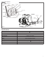
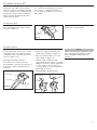
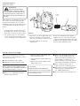
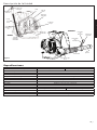
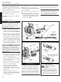
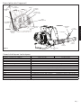
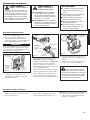
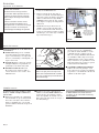
Unit Description
Throttle Lever
Air Cleaner
Cover
Spark Plug
Starter
Handle
Fuel Tank
Fuel Filler
Cap
Swivel Tube
Flexible
Tube
90° Discharge Tube
Exhaust Outlet
Volute
Case
Engine
Cover
Figure 3
Stop Switch
EB8520
Stop Switch
Throttle
Lever
EB8520RT
Throttle
Assembly
Specications
Model EB8520 EB8520RT
Dry Weight (without Blower Tubes) 11.6 kg/25.57 lbs 11.5 kg/25.35 lbs
Dimensions (L xWxH)
350 x 465 x 545 mm
Engine Type 4 cycle air-cooled gasoline engine, vertical-cylinder
Bore & Stroke 51 x 39 mm (2.01 x 1.54 inches)
Displacement 79.7cc (4.86 cu. inches)
Max Output/min
-1
3.21 kW/4.3 hp @ 7,500 min
-1
Fuel/Oil Ratio 50:1 with Shindaiwa Premium 2-cycle mixing oil
Carburetor Walbro rotary-type with primer bulb
Ignition CDI (Capacitor Discharge Ignition)
Spark Plug NGK CMR5H
Starting Recoil Starter
Stopping Push Button Switch (Grounding type) Slide Switch (Grounding type)
Fuel Tank Capacity 2.0 liters (67.6 oz)
Exhaust Spark Arrester Muffler
Air Filtration Dry Element with pre-filter
Specifications are subject to change without notice.

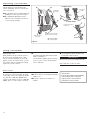
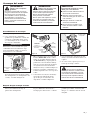
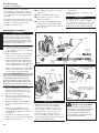
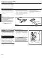
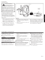
Static Wire
Connector
Static Wire
Fold wire
Flexible Tube
Swivel
Tube
Anti-Static
Wire
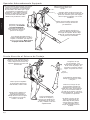
6
Flexible Tube
89mm Clamp
102mm
Clamp
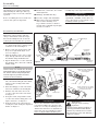
Figure 4
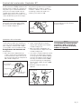
Swivel Tube
Swivel
Tube
Lock Pin
Lock Slot
Rotate clockwise to lock making
sure the 3 lines are aligned on
both tube and nozzle.
IMPORTANT!
Blower tube installation affects blower
performance! Make sure the tubes and
nozzle are correctly assembled per above,
and that all connections are tight. Blower
tubes may come apart during use unless
tubes are aligned and locked into place.
Align the lock pins with the lock
slots, and push the tube and
nozzle together.
Figure 6
Assembly
WARNING!
Danger from rotating
impeller!
Stop the engine before installing or
removing the blower tubes! Never
perform any maintenance or assem-
bly procedures on this unit while the
engine is running!
Figure 5
Handgrip
Short Nozzle
(ø65 mm)
Straight Tube
Long Nozzle
(ø74 mm)
90° Discharge Tube
Prior to Assembly
Using Figure 3 as a guide, familiarize your-
self with the blower and its components.
Understanding the unit helps ensure top
performance, longer service life, and safer
operation.
Before assembling the blower, make sure
you have all required components.
IMPORTANT!
The terms “left”, “left-hand”, “LH”; “right”,
“right-hand”, and “RH”; “front” and “rear”
refer to directions as viewed by the opera-
tor during normal operation.
Power unit and blower assembly.
■
Flexible tube, swivel tube, two nozzles ■
and straight tube.
Handgrip (Non RT unit only).
■
Two tube clamps (102 and 89mm). ■
This Owner’s/Operator’s Manual ■
and a tool kit containing a tool
bag, 4 mm hex wrench, 5 mm hex
wrench and a combination spark plug
wrench/screwdriver.
Lead wire assembly (anti-static).
■
Carefully inspect all components for damage.
Assembling the Blower
Place the blower upright on the ground 1.
or a sturdy work surface and note parts
orientation as shown in Figure 4.
Remove static wire from package and
2.
fix eyelet to right hand engine cover
screw. See Figure 5.
Turn the discharge tube out to a right
3.
angle and slip anti-static wire through
the 102mm clamp and flexible tube.
Slip the flexible tube over the end of the
4.
90° discharge tube, and secure with the
102mm clamp.
IMPORTANT!
This unit is equipped with a static dis-
charge reduction wire. This wire helps
direct static buildup into the air stream
reducing the felt amount to the operator.
NOTE:
Check to make sure that the 90° discharge
tube swivels freely. If any binding is pres-
ent, loosen 102mm clamp and pull wire
towards engine to get more slack and
recheck for free movement.
Insert the static wire through the swivel 5.
tube, then install and tighten the 89mm
clamp over the rotating band on the
swivel tube.
Slide the handgrip over the swivel tube
6.
and secure with the bolt and wingnut.
Fold the end of the static wire back
7.
over the connection of the swivel tube.
See Figure 5.
Grasp the nozzle, and push the nozzle
8.
over the swivel tube locking pins secur-
ing the static wire. See Figure 6.
Lock the nozzle to the swivel tube by
9.
rotating the nozzle noting the alignment
marks. See Figure 6.

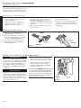
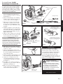
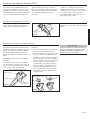
Static Wire
Connector
Static Wire
Fold Wire
Flexible Tube
Swivel
Tube
Throttle
Assembly
Throttle Cable
Holder
Throttle Cable Holder
7
Loops
Lock Pin
Lock Slot
Rotate clockwise to lock making
sure the 3 lines are aligned on
both tube and nozzle.
Align the lock pins with the lock
slots, and push the tube and
nozzle together.
A
B
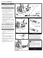
Assembling the RT Blower
IMPORTANT!
Blower tube installation affects blower
performance! Make sure the tubes and
nozzle are correctly assembled per above,
and that all connections are tight. Blower
tubes may come apart during use unless
tubes are aligned and locked into place.
Figure 7
Figure 9
Place the blower upright on the ground 1.
or a sturdy work surface and note parts
orientation as shown in Figure 7.
Remove static wire from package and
2.
fix eyelet to right hand engine cover
screw. See Figure 8.
Turn the discharge tube out to a right
3.
angle and slip anti-static wire through
the 102mm clamp and flexible tube.
Install throttle cable holder just forward
4.
of the 102 mm clamp, pinching loops
together to fit over end of flexible tube.
See Figures 10A and 10B.
Slip the flexible tube over the end of the
5.
90° discharge tube, and secure with the
102 mm clamp.
Slide the throttle assembly over the swivel 6.
tube. Do not tighten clamp at this time.
WARNING!
Danger from rotating
impeller!
Stop the engine before installing or
removing the blower tubes! Never
perform any maintenance or assem-
bly procedures on this unit while the
engine is running!
IMPORTANT!
This unit is equipped with a static dis-
charge reduction wire. This wire helps
direct static buildup into the air stream
reducing the felt amount to the operator.
Figure 8
Figure 10B
Insert the static wire through the swivel 7.
tube, then install and tighten the 89mm
clamp over the rotating band on the
swivel tube.
Fold the end of the static wire back over
8.
the connection of the swivel tube. See
Figure 8.
Grasp the nozzle, and push the nozzle
9.
over the swivel tube locking pins secur-
ing the static wire. See Figure 9.
Lock the nozzle to the swivel tube by
10.
rotating the nozzle noting the alignment
marks. See Figure 9.
Adjust throttle assembly for best operator 11.
comfort and tighten two socket-head
screws.
Flexible Tube
Throttle
Assembly
89mm Clamp
102mm
Clamp
Swivel Tube
Straight Tube
Short Nozzle
(ø65 mm)
Swivel
Tube
90° Discharge
Tube
Anti-Static
Wire
Throttle Cable
Holder
Long Nozzle (ø74 mm)
Figure 10A
NOTE:
Check to make sure that the 90° dis-
charge tube swivels freely. If any binding
is present, loosen 102 mm clamp and
pull wire towards engine to get more
slack and recheck for free movement.
The blower should now be ready
for use.
Assembly (continued)

Mixing fuel
CAUTION!
Never use any type of gasoline
■
containing more than 10% alcohol
by volume! Some types of gasoline
contain alcohol as an oxygenate.
Oxygenated gasoline may cause
increased operating temperatures.
Under certain conditions, alcohol-
based gasoline may also reduce
the lubricating qualities of some
2-cycle mixing oils.
Generic oils and some outboard
■
oils may not be intended for use
in high-performance C4 engines,
and should never be used in your
Shindaiwa engine.
8
NEVER ■ smoke or light res near the
engine.
ALWAYS
■ stop the engine and allow
it to cool before refueling.
ALWAYS
■ Wipe all spilled fuel and
move at least 3 meters from the fuel-
ing point and source before starting.
NEVER
■ place ammable material
close to the engine mufer.
NEVER
■ operate the engine with-
out the mufer and spark arrester
screen in place.
FUEL IS HIGHLY FLAMABLE. ■
ALWAYS ■ store gasoline in a con-
tainer approved for ammable liquids.
ALWAYS
■ inspect the unit for fuel
leaks before each use. During each
rell, check that no fuel leaks from
around the fuel cap and/or fuel tank. If
fuel leaks are evident, stop using the
unit immediately. Fuel leaks must be
repaired before using the unit.
ALWAYS ■ move the unit at least 3
meters away from a fuel storage
area or other readily ammable
materials before starting the engine.
Mixing fuel
Filling the fuel tank
CAUTION!
This engine is designed to operate
on a 50:1 mixture consisting of
unleaded gasoline and ISO-L-EGD
or JASO FC class 2-cycle mixing oil
only. Use of non-approved mixing
oils can lead to excessive carbon
deposits.
Use only fresh, clean unleaded gasoline ■
with a pump octane of 87 or higher.
Mix all fuel with a 2-cycle air-cooled
■
mixing oil that meets or exceeds ISO-L-
EGD and/or JASO FC classified oils at
50:1 gasoline/oil ratio.
Examples of 50:1 mixing quantities
WARNING!
Minimize the Risk of Fire
Gasoline 2-cycle mixing oil
liters milliliters
2.5 - 1
50 ml
5 - 1 100 ml
10 - 1 200 ml
20 - 1 400 ml
IMPORTANT!
Mix only enough fuel for your immediate
needs! If fuel must be stored longer than 30
days and
oil with fuel stabilizer is not
used, it should first be treated with a fuel
stabilizer such as STA-BIL™.
Oil is a registered JASO FC classi-
fied oil and also meets or exceeds ISO-L-EGD
performance requirements. Shindaiwa One is
recommended for use in all Shindaiwa low emis-
sions engines. Shindaiwa One also includes a
fuel stabilizer.
Remove the Fuel
Filler Cap
Place the unit on a flat, level surface.1.
Clear any dirt or other debris from 2.
around the fuel filler cap.
Remove the fuel cap, and fill the tank 3.
with clean, fresh fuel.
Reinstall the fuel filler cap and tighten 4.
firmly.
Wipe away any spilled fuel before start-5.
ing the unit.

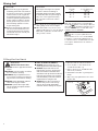
EB8520RT
EB8520
Choke DOWN:
Open
Fuel Primer
Bulb
Choke UP:
Closed
9
WARNING!
Danger from thrown dust or
debris!
Always wear eye protection when
operating this machine! Never direct
the blower stream toward people or
animals!
Never operate this blower unless all
controls are properly installed and in
good working order.
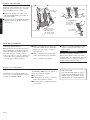
Starting the Engine
WARNING!
Danger from rotating
impeller!
The impeller will rotate whenever
the blower is operated! Never oper-
ate this blower unless the intake
cover and blower tubes are properly
installed and in good working order!
CAUTION!
The recoil starter can be damaged
by abuse!
Never pull the starter cord to its full
■
length!
Always engage the starter before
■
cranking the engine!
Always rewind the starter cord slowly!
■
Never operate the blower if blower ■
tubes are missing or damaged!
Place the blower on the ground. 1.
Prime the fuel system by repeatedly 2.
depressing the fuel primer bulb until
no air bubbles are visible in the fuel
discharge line.
Figure 12
Cold Engine Only.3. Choke the engine
by moving the choke lever up (choke is
closed). See Figure 12.
IMPORTANT!
The primer system only pushes fuel
through the carburetor. Repeatedly press-
ing the primer bulb will not flood the
engine with fuel.
244HROTTLE,F
Figure 13
Full Throttle
Idle
Move the throttle lever to half throttle. 4.
RT Model: Slide the ignition switch to
the “I” (ON) position, then depress the
throttle lever halfway and lock throttle
by moving the throttle lock lever half-
way down. See Figure 13.
Hold the blower firmly with your left
5.
hand on the volute case.
Using your right hand, pull the starter
6.
handle slowly until you feel the starter
engage. See Figure 14.
Full Throttle
Throttle Lever
ON
Throttle Lock
Lever
Ignition
Switch
As the starter engages, pull the starter 7.
handle upward rapidly.
If necessary, repeat Steps 6 and 7 until
8.
the engine starts.
WARNING!
Never operate the blower
unless all controls are properly
installed and in good working order.
Never operate the blower if the cyl-
inder cover is missing or damaged!
Starting procedure
Open the choke (if it is not already ■
open) by moving the choke lever down.
If the engine does not continue to run,
■
repeat the appropriate starting proce-
dures for a cold or warm engine.
When The Engine Starts
Figure 14
Pull upward
rapidly
After the engine starts, allow the engine ■
to warm up at idle 2 or 3 minutes before
operating the unit.

244HROTTLE,F
Figure 15
Stop Button
Ignition Switch
OFF
EB8520
EB8520RT
10
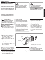
Adjusting Engine Idle Speed
IMPORTANT!
A clean and unrestricted airflow is essen-
tial to your blower’s engine performance
and durability! Before attempting any
carburetor adjustments, inspect and clean
the engine air filter as described in the
maintenance section of this manual.
Idle Increase
Idle Decrease
Idle Adjustment
Screw
Figure 16
Place the unit on the ground and start 1.
the engine, then allow it to idle 2-3 min-
utes until warm.
If a tachometer is available, the engine 2.
idle speed should be final adjusted to
2,000 (±200) min
-1
. See Figure 16.
NOTE:
Carburetor fuel mixture adjustments are
preset at factory on units with emission
control systems and cannot be serviced
in the eld.
IMPORTANT!
Blower tubes and the air cleaner must
be in place while adjusting engine idle!
Engine idle speed will also be affected if
the blower tubes are blocked or incor-
rectly installed!
Repeat the appropriate starting procedures
for warm or cold engine. If the engine
still will not start, follow the “Starting a
Flooded Engine” procedure.
Disconnect the spark plug lead, and
1.
remove the spark plug (see page 12 for
procedures).
If the spark plug is fouled or is soaked
2.
with fuel, clean or replace the plug as
required.
Cool the engine by allowing it to run at
1.
idle for 2–3 minutes.
Push and hold the Stop button down
2.
until the engine stops. RT Model: Slide
the ignition switch towards the rear to
“O” (OFF). See Figure 15.
With the spark plug removed, open
3.
the choke, put the throttle lever in the
full throttle position, then clear excess
fuel from the combustion chamber by
cranking the engine several times.
Install and tighten the spark plug, and
4.
reconnect the spark plug lead.
Repeat the starting procedures for a
5.
warm engine.
If the engine still fails to start or fire,
6.
refer to the troubleshooting flow chart
at the end of this manual.
If The Engine Does Not Start
Starting A Flooded Engine
Starting the Engine (continued)
Stopping The Engine

Thumb
Control Lever
11
RT Throttle RT
Turbo
dB
Throttle Limiter
The RT blower has a throttle limiter func-
tion that allows the operator to pre-set the
maximum engine speed. This is useful for
reducing the noise emitted by the blower
in noise sensitive areas.
Setting Throttle Limiter:
For reduced noise setting, move the
throttle limiter located on the right side of
the throttle control to the dB setting. See
Figure 18.
Turbo Setting
dB Setting
Throttle Limiter
Lever
Figure 18
Throttle Limiter Adjustment
Throttle Control RT
Figure 17
To bring min
-1
down to idle, push lever
back up into original position.
Adjusting Throttle Limiter:
Remove the plug located at the top of 1.
the throttle assembly. See Figure 19.
Move the throttle limiter lever to the
2.
“dB” setting. See Figure 19.
With the engine running and while 3.
depressing the throttle trigger, use a small
Phillips screw driver to turn the adjustment
screw clockwise to decrease min
-1
and
counter-clockwise to increase until desired
limited min
-1
is achieved.
Reinstall limiter adjustment plug.4.
Figure 19
Remove limiter
adjustment plug
The RT blower is equipped with a multi- func-
tion throttle control. The “Cruise” function
allows the operator to use a thumb controlled
lever for constant speed use without using the
throttle trigger. This is useful for limiting the
fatigue caused from holding the throttle for
extended periods of time.
Turbo
dB
Turbo
dB
On the opposite side, a two position “Lim-
iter” control allows full engine speed when
set for “Turbo” or limits the throttle to a
pre-set engine speed when set to low noise
(dB) setting.
Using the right thumb, push the throttle lock
lever down until the desired min
-1
setting is
reached. See Figure 17
.
Cruise Function
NOTE:
With the throttle limiter adjusted to 3,850
min
-1
, the RT blower will have a sound
level of 65 dB(A) measured at 15m
(50 feet).

Comfortable
back pads
B
B
A
A
A
Figure 20
To tighten straps…
To loosen straps…
Pull strap
loops
down.
Quick-adjust
buckle
Pull the quick-adjust
buckles up…
…and pull the
straps down.
12
Adjusting The Harness
The Shindaiwa blower features an
advanced harness system that helps
ensure maximum operator comfort and
ease of operation.
The shoulder harness is filled with soft
■
padding for reduced operator fatigue.
The simplified adjustment system
■
makes it easy to match the harness to
every body size and type.
Using The Blower
Operating Tips
In the hands of an experienced operator,
the blower can efficiently move a wide
variety of debris ranging from grass clip
-
pings to gravel. As a general rule, operate
your blower at the lowest throttle setting
required to get the job done:
Use full throttle when moving heavy
■
loads such as dirt or snow.
Use low throttle settings when clear
-
Use low throttle settings when clear-Use low throttle settings when clear
■
ing lightweight materials from around
lawns or shrubbery.
Use medium to higher throttle settings
■
to move grass or leaves from parking
lots or walkways.
IMPORTANT!
Blower noise increases at higher throttle
settings! Always use the lowest throttle set
-
settings! Always use the lowest throttle set-settings! Always use the lowest throttle set
ting required to get the job done!
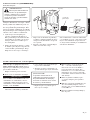
This engine is equipped with a heat sensor
in order to prevent overheating. If engine
overheating occurs, the engine speed will
be reduced to 5,000 min
-1
(RPM). If the
engine speed will not rise above 5,000 min
-1
(RPM), please cool the engine as follows .
CAUTION!
If the engine speed is automatically
reduced again after cooling the
engine, please consult with an
authorized servicing dealer.
Heat sensor
Stop the engine.
■
Remove any leaves and debris blocking
■
intake cover.
Keep the engine speed at idle for 1
■
minute
.
Quick- disconnect
spring hook
Pull on the loops to quickly
tighten the harness straps.
A = Adjust height
B = Adjust angle

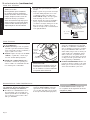
To remove the cover, loosen the
thumbscrews and lift.
Air Cleaner
Element
Cover
Figure 21
Pre-Filter
Thumbscrews
13
IMPORTANT!
MAINTENANCE, REPLACEMENT
OR REPAIR OF EMISSION CONTROL
DEVICES AND SYSTEMS MAY BE PER
-
DEVICES AND SYSTEMS MAY BE PER-DEVICES AND SYSTEMS MAY BE PER
FORMED BY ANY REPAIR ESTABLISH
-
MENT OR INDIVIDUAL, HOWEVER,
WARRANTY REPAIRS MUST BE PER
-
WARRANTY REPAIRS MUST BE PER-WARRANTY REPAIRS MUST BE PER
FORMED BY A DEALER OR SERVICE
CENTER AUTHORIZED BY SHINDAIWA
CORPORATION THE USE OF PARTS
THAT ARE NOT EQUIVALENT IN PER
-
THAT ARE NOT EQUIVALENT IN PER-THAT ARE NOT EQUIVALENT IN PER
FORMANCE AND DURABILITY TO
AUTHORIZED PARTS MAY IMPAIR THE
EFFECTIVENESS OF THE EMISSION
CONTROL SYSTEM AND MAY HAVE
A BEARING ON THE OUTCOME OF A
WARRANTY CLAIM.
Maintenance
Daily Maintenance
WARNING!
To reduce re hazard, keep
the engine and mufer free of dirt,
debris, and leaves.
WARNING!
Non-standard parts may not
operate properly with your unit and
may cause damage and lead to per
-
sonal injury.
NOTE:
Using non-standard replacement parts
could invalidate your Shindaiwa warranty.
Every 10 Hours
(more frequently in dusty conditions)
CAUTION!
Never operate the blower if the air
cleaner assembly is damaged or
missing!
Inspect the engine, tank, and hoses
■
for possible fuel leaks, and repair as
necessary.
Inspect the entire blower for loose,
■
damaged, or missing components, and
repair as necessary.
Carefully remove any accumulations
■
of dirt or debris from the muffler and
fuel tank. Dirt build-up in these areas
can lead to engine overheating, fire or
premature wear.
IMPORTANT!
Direct the air stream at the inside face of
the filter only!
WARNING!
Before performing any main
-
tenance, repair or cleaning work on
the unit, make sure the engine is com
-
pletely stopped. Disconnect the spark
plug wire before performing service or
maintenance work.
CAUTION!
The engine is cooled by air drawn
into the air intake cover on the blower
housing. The blower fan then pushes
the cooling air through an opening in
the fan housing, forcing it past the cyl
-
inder cooling ns. Failure to keep the
cooling system and its passages clear
of debris will likely result in engine
overheating, a major cause of seri
-
ous engine problems that can lead to
failure.
Prior to each workday, perform the
following:
Remove all dirt and debris from blower
■
exterior and the engine. Check the
cooling fins and air cleaner for clog
-
ging and clean as necessary.
Remove the air cleaner cover by loosen
-
1.
ing the thumbscrews and lifting. See
Figure 21.
Remove and inspect the pre-filter. If the
2.
pre-filter is torn or otherwise damaged,
replace it with a new one.
IMPORTANT!
The blower uses a special high capacity
dry-type air filter element. The filter should
not be cleaned with a liquid cleaner and
must NEVER be oiled!
Clean the pre-filter with soap and water.
3.
Let dry before reinstalling.
Inspect the air cleaner element. If
4.
the element is damaged or distorted,
replace it with a new one.

Counter-clockwise
to remove.
Clean the spark
plug and check
the gap at the
electrode.
Fuel Tank
139/150-Hour Maintenance
Fuel
Filter
Hooked
Wire
spark plug gap--all models
0,6 - 0,7 mm
(0.024 in.)
Figure 22
Figure 23
NGK CMR5H
14
INSPECTION Inspect the entire ■
blower and tubes for damage, includ-
ing loose or missing components, and
repair as necessary.
(more frequently if reduced performance
is noted)
Inspect the filter element for signs of ■
contamination from debris. A contami-
nated fuel filter should be replaced with
a new Shindaiwa replacement element.
Before reinstalling the filter, inspect the
condition of the fuel line. If you note
damage or deterioration, the blower
should be removed from service until
it can be inspected by a Shindaiwa-
trained service technician.
COOLING SYSTEM Use a wood or
■
plastic scraper and a soft brush to
remove dirt and debris from the cylin-
der fins and crankcase.
Every 50 Hours
Every 10/15 Hours
CAUTION!
Never allow dirt or debris to enter the
cylinder bore! Before removing the
spark plug, thoroughly clean the spark
plug and cylinder head area!
Allow the engine to cool before serv-
icing the spark plug! Cylinder threads
can be damaged by tightening or loos-
ening the spark plug while the engine
is hot!
CAUTION!
Make sure you do not pierce the fuel
line with the end of the hooked wire.
The line is delicate and can be dam-
aged easily.
FUEL FILTER Use a hooked wire to ■
extract the fuel filter from inside the
fuel tank.
Maintenance
Use the spark plug wrench to remove 1.
the spark plug.
Clean and adjust the spark plug gap
2.
to 0.6mm (0.024”). If the plug must be
replaced, use a NGK CMR5H or equiva-
lent type plug of the correct heat range.
Install the spark plug finger-tight
3.
in the cylinder head, then tighten it
firmly with the spark plug wrench. If a
torque wrench is available, torque the
spark plug to 16.7-18.6 Nm (148-165
inch- pounds).
SPARK PLUG Replace the spark plug
■
with a NGK CMR5H (or equivalent),
gapped to 0.6 mm (0.024”).
NOTE:
The NGK CMR5H also meets the require-
ments for electro magnetic compliance (EMC).
Replace the spark plug annually: Use ■
onlyNGK CMR5H or equivalent resis-
tor type spark plug of the correct heat
range. Set spark plug electrode gap to
0.6 mm (0.024 inch).
Maintenance after first 139-hours,
then every 150-hours thereafter.
Combustion chamber should be decar-
■
bonized, and the valve clearance should
be adjusted. It is highly recommended
that this is done by a Shindaiwa-trained
service technician.

Mufer
Arrester
Screen
Arrester Screen Cover
Figure 24
15
Long Term Storage
CAUTION!
Gasoline stored in the carburetor for
extended periods can cause hard starting,
and could also lead to increased service
and maintenance costs.
Whenever the unit will not be used for
30
days or longer, use the following procedures
to prepare it for storage:
Clean external parts thoroughly.
■
Drain all the fuel from the fuel tank.
■
Remove the remaining fuel from the
■
fuel lines and carburetor:
Remove the spark plug and pour about
■
10 cm
3
of 2-cycle mixing oil into the
cylinder through the spark plug hole.
Slowly pull the recoil starter 2 or 3
times so oil will evenly coat the interior
of the engine. Reinstall the spark plug.
Before storing the unit, repair or
■
replace any worn or damaged parts.
Remove the air cleaner element from the
■
unit and clean it as outlined in the sec
-
tion, "10-Hour Maintenance".
Store the unit in a clean, dust-free area.
■
Prime the primer bulb until no more
1.
fuel is passing through.
Start and run the engine until it stops
2.
running.
Repeat steps 1 and 2 until the engine
3.
will no longer start.
IMPORTANT!
All stored fuels should be stabilized with a
fuel stabilizer such as STA-BIL™ if Shindaiwa
One oil with fuel stabilizer is not used.
Inspect the screen carefully, and replace
3.
any screen that has been perforated,
distorted, or is otherwise unserviceable.
Press the spark arrester into the
4.
exhaust base.
If carbon accumulation in the muffler or
cylinder is severe, or if you do not notice
an improvement in performance after ser
-
an improvement in performance after ser-an improvement in performance after ser
vicing, have the unit inspected by an autho
-
rized servicing Shindaiwa dealer.
Spark Arrester
Hard starting or a gradual loss of perform-
ance can be caused by carbon deposits
lodged in the spark arrester screen. For
maximum perform-ance, the spark arrester
screen should be periodically cleaned as
follows:
Remove engine cover to expose muf
-
Remove engine cover to expose muf-Remove engine cover to expose muf
1.
fler. Remove the spark arrester from
the muffler. The arrester is press-fit in
place; there are three screws to remove.
Use a plastic scraper or wire brush to
2.
remove carbon deposits from the arres-
ter screen and wipe clean exhaust base.
WARNING!
Never operate this blower
with a damaged or missing mufer or
spark arrester! Operating with missing
or damaged exhaust components is a
re hazard, and can also damage your
hearing!
Maintenance

16
NO
NO
NO
NO
NO
Priming pump not functioning
properly..
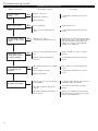
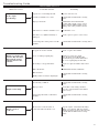
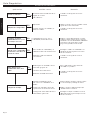
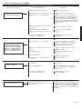
Troubleshooting Guide
YES
YES
YES
YES
YES
Does the engine
crank?
Does the tank contain
fresh fuel of the proper
grade?
Is fuel visible and
moving in the return
line when priming?
Is there spark at
the spark plug wire
terminal?
Check the spark plug.
The plug is damaged internally or of
the wrong size.
What To Check Possible Cause Remedy
ENGINE DOES NOT START
Faulty recoil starter.
Fluid in the crankcase.
Internal damage.
Loose spark plug.
Excess wear on cylinder, piston,
rings.
Fuel incorrect, stale, or
contaminated; mixture incorrect.
Check for clogged fuel filter and/or
vent.
The ignition switch is in “O” (OFF)
position.
Shorted ignition ground.
Faulty ignition unit.
If the plug is wet, excess fuel may be
in the cylinder.
The plug is fouled or improperly
gapped.
Consult with an authorized servicing
dealer.
Tighten and re-test.
Consult with an authorized servicing
dealer.
Refill with fresh, clean unleaded gasoline
with a pump octane of 87 or higher mixed
with 50:1 Shindaiwa Premium 2-cycle
mixing oil or with an equivalent high
quality 2-cycle mixing oil.
Replace fuel filter or vent as required.
Restart.
Move switch to “I” (ON) position and
restart.
Consult with an authorized servicing
dealer.
Crank the engine with the plug removed,
reinstall the plug, and restart.
Clean and regap the plug to 0.6mm.
Restart.
Replace the spark plug. Check the unit
Specifications page for the proper spark
plug for your unit. Restart.
Good compression?
Consult with an authorized servicing
dealer.

17
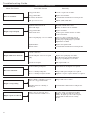
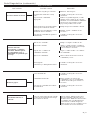
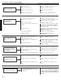
Troubleshooting Guide
Operator is overworking the unit.
Carburetor mixture is too lean.
Improper fuel ratio.
Fan, fan cover, cylinder fins dirty or
damaged
Carbon deposits on the piston or in the
muffler.
Clogged air cleaner element.
Loose or damaged spark plug.
Air leakage or clogged fuel line.
Operate at slower rate.
Consult with an authorized servicing
dealer.
Refill with clean fresh unleaded
gasoline with a pump octane of 87 or
higher, mixed with Premium 2-cycle
mixing oil at a 50:1 gasoline/oil ratio.
Clean, repair or replace as necessary.
Consult with an authorized servicing dealer
Clean or replace the air filter
Tighten or replace the spark
plug. Restart. Check the Product
Specifications page in this manual for
the correct spark plug for this unit.
Repair or replace fuel filter and/or fuel
line.
Water in the fuel.
Piston seizure.
Faulty carburetor and/or diaphragm
Overheating condition.
Improper fuel.
Carbon deposits in the combustion
chamber.
Check fuel octane rating; check for
presence of alcohol in the fuel. Refuel
as necessary.
Consult with an authorized servicing
dealer.
Refill with fresh fuel/oil mixture.
Consult with an authorized servicing
dealer.
Consult with an authorized servicing
dealer.
Is the engine
overheating?
Engine is rough at all
speeds. May also have
black smoke and/or
unburned fuel at the
exhaust.
Engine is knocking.
LOW POWER OUTPUT
What To Check Possible Cause Remedy
Fallen leaves or debris on intake cover..
Clean intake cover..
Engine speed is
reduced.
Heat sensor is activated, due to
restricted air flow at intake cover.
Stop the engine. Clean debris blocking
intake cover. Restart. Idle more than 1
minute. If engine speed is reduced again,
consult with an authorized servicing
dealer.

18
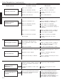
Troubleshooting Guide
ADDITIONAL PROBLEMS
Fuel tank empty.
Clogged fuel filter.
Water in the fuel.
Shorted spark plug or loose terminal.
Ignition failure.
Piston seizure.
Ground (stop) wire is disconnected or
switch is defective
Overheating due to incorrect spark
plug
Clogged air filter.
Clogged fuel filter.
Lean fuel/air mixture.
Idle speed set too low.
Ignition switch turned off.
Refuel. See Fuel section of manual.
Replace fuel filter.
Drain; replace with clean fuel. See Fuel
section of manual..
Clean or replace spark plug. Check
the Specifications page in this manual
for the proper spark plug for your unit.
Tighten the terminal.
Replace the ignition unit.
Consult with an authorized servicing dealer.
Test and replace as required.
Replace the spark plug. Check the
Specifications page in this manual for
the proper spark plug for your unit.
Clean or replace the air filter.
Replace the fuel filter.
Consult with an authorized servicing dealer.
Reset the switch and re-start.
Overheated engine.
Debris build up in impeller.
Loose or damaged impeller.
Idle engine until cool.
Clean debris from impeller as required.
Inspect and replace impeller as required.
Loose or damaged engine mounts.
Blower intake or discharge ports or
tubes are clogged with debris..
Impeller blades are missing or
damaged.
Tighten or replace engine mounts as required.
Inspect and remove debris.
Consult with a authorized servicing dealer.
What To Check Possible Cause Remedy
Poor acceleration.
Engine stops abruptly.
Engine difficult to shut off.
Excessive vibration.
Engine overspeeding.
Heat sensor is activated, due to
restricted air flow at intake cover.
Stop the engine. Clean debris blocking
intake cover. Restart. Idle more than 1
minute. If engine speed is reduced again,
consult with an authorized servicing
dealer.
Engine speed is reduced.
Adjust: 2,000 (±200) min
-1
.

19
Emission System Warranty Statement
Your Warranty Rights and Obligations
The California Air Resources Board, the U.S. Environmental
Protection Agency and Shindaiwa Inc. are pleased to explain the
exhaust and evaporative emission control system warranty on
your new small off-road (non-road) engine.
In California, new small off-road engines must be designed,
built, and equipped to meet the State’s stringent anti-smog stan-
dards. In other states, new 1997 and later non-road engines must
meet the Federal EPA’s stringent anti-smog standards.
Shindaiwa Inc. must warrant the emission control system on
your small off-road engine for the periods of time listed below,
provided there has been no abuse, neglect, or improper mainte-
nance of your small off-road engine.
Your engine exhaust and evaporative emission control system
includes parts such as the carburetor, fuel tank, the ignition sys-
tem and, if equipped, the catalytic converter. These components
are specifically listed below.
Where a warrantable condition exists, Shindaiwa Inc. will
repair your small off-road engine at no cost to you including
diagnosis, parts, and labor.
Manufacturer’s Warranty Coverage
When sold within the U.S., this engine’s emission control sys-
tem is warranted for a period of two (2) years from the date this
product is first delivered to the original retail purchaser.
During the warranty period, Shindaiwa Inc. will, at their
option, repair or replace any defective emission-related compo-
nent on this engine. During the original Warranty Period, these
Warranty Rights are automatically transferable to subsequent
owners of this product.
What is Covered by this Warranty
Carburetor Internal Components1.
Throttle Valve, Needle, Jet, Metering Diaphragm ■
Fuel Tank2.
Ignition System Components3.
Ignition Coil ■
Flywheel Rotor ■
Catalytic Converter (if originally equipped)4.
The emission control system for your particular Shindaiwa
engine may also include certain related hoses and connectors.
Owners Warranty Responsibilities
As the small off-road engine owner, you are responsible for
the performance of the required maintenance listed in this
owners manual. Shindaiwa Inc. recommends that you retain all
receipts covering maintenance on your small off-road engine,
but Shindaiwa Inc. cannot deny warranty solely for the lack
of receipts or for your failure to ensure the performance of all
scheduled maintenance.
As the small off-road engine owner, you should be aware,
however, that Shindaiwa Inc. may deny you warranty coverage
if your small off-road engine or a part has failed due to abuse,
neglect, improper maintenance, or unapproved modifications.
You are responsible for presenting your small off-road engine
to an authorized Shindaiwa Dealer as soon as a problem exists.
The warranty repairs should be completed in a reasonable
amount of time, not to exceed 30 days.
If you have any questions regarding your warranty rights and
responsibilities, you should contact a Shindaiwa customer service
representative at (503) 692-3070 or your local Shindaiwa Dealer.
Consequential Damages
In the event that other component parts of this product are
damaged by the failure of a warranted part, Shindaiwa Inc. will
repair or replace such component parts at no charge to you.
What is Not Covered
Failures caused by abuse, neglect, or improper maintenance ■
procedures.
Failures caused by the use of modified or non-approved
■
parts or attachments.
This Warranty is Administered by:
Shindaiwa Inc.
11975 S.W. Herman Rd.
Tualatin, OR 97062
(503) 692-3070

Shindaiwa Inc.
11975 S.W. Herman Rd.
Tualatin, Oregon 97062
Telephone: 503 692-3070
Fax: 503 692-6696
www.shindaiwa.com
Shindaiwa Corporation
Head Office: 6-2-11 Ozuka
Nishi, Asaminami-Ku
Hiroshima, 731-3167, Japan
Telephone: 81-82-849-2220
Fax: 81-82-849-2481
©2008 Shindaiwa, Inc.
Part Number 68915-94310
Revision 9/08
Shindaiwa is a registered trademark
of Shindaiwa, Inc.
Specifications subject to change without
notice.
NOTES
Page is loading ...
Page is loading ...
Page is loading ...
Page is loading ...
Page is loading ...
Page is loading ...
Page is loading ...
Page is loading ...
Page is loading ...
Page is loading ...
Page is loading ...
Page is loading ...
Page is loading ...
Page is loading ...
Page is loading ...
Page is loading ...
Page is loading ...
Page is loading ...
Page is loading ...
Page is loading ...
Page is loading ...
Page is loading ...
Page is loading ...
Page is loading ...
Page is loading ...
Page is loading ...
Page is loading ...
Page is loading ...
Page is loading ...
Page is loading ...
Page is loading ...
Page is loading ...
Page is loading ...
Page is loading ...
Page is loading ...
Page is loading ...
Page is loading ...
Page is loading ...
Page is loading ...
Page is loading ...
-
 1
1
-
 2
2
-
 3
3
-
 4
4
-
 5
5
-
 6
6
-
 7
7
-
 8
8
-
 9
9
-
 10
10
-
 11
11
-
 12
12
-
 13
13
-
 14
14
-
 15
15
-
 16
16
-
 17
17
-
 18
18
-
 19
19
-
 20
20
-
 21
21
-
 22
22
-
 23
23
-
 24
24
-
 25
25
-
 26
26
-
 27
27
-
 28
28
-
 29
29
-
 30
30
-
 31
31
-
 32
32
-
 33
33
-
 34
34
-
 35
35
-
 36
36
-
 37
37
-
 38
38
-
 39
39
-
 40
40
-
 41
41
-
 42
42
-
 43
43
-
 44
44
-
 45
45
-
 46
46
-
 47
47
-
 48
48
-
 49
49
-
 50
50
-
 51
51
-
 52
52
-
 53
53
-
 54
54
-
 55
55
-
 56
56
-
 57
57
-
 58
58
-
 59
59
-
 60
60


Shindaiwa EB8520 User manual
- Category
- Air blowers/dryers
- Type
- User manual
- This manual is also suitable for
Ask a question and I''ll find the answer in the document
Finding information in a document is now easier with AI
in other languages
- français: Shindaiwa EB8520 Manuel utilisateur
- español: Shindaiwa EB8520 Manual de usuario
Related papers
-
Shindaiwa EB240S User manual
-
Shindaiwa Blower EB344 User manual
-
-
-
-
-
-
-
-