Turboair ISCHIA IX/A/60 User manual
- Category
- Cooker hoods
- Type
- User manual
This manual is also suitable for

10401251455/01
CAPPA CAMINO
ISTRUZIONI DI MONTAGGIO
CHIMNEY HOOD
INSTALLATIONS INSTRUCTIONS
KAMIN-HAUBE
EINBAU-ANWEISUNGEN
HOTTE CHEMINEE
INSTRUCTIONS DE MONTAGE
CAMPANA DECORATIVA
INSTRUCCIONES DE USO
HOTE DA CHAMINÉ
INSTRUÇÕES DE MONTAGEM
Page is loading ...
Page is loading ...
Page is loading ...

odori viene aspirata prima attraverso il filtro per grassi e (se la cappa è filtrante) attraverso
il filtro antiodori. L’efficienza dell’apparecchio dipende dallo stato in cui si trovano i filtri.
Il filtro anti-odori
L’aria aspirata passa dal filtro carboattivo e viene depurata dagli odori. Questo filtro non
può essere lavato e dovrà essere sostituito a seconda della frequenza d’uso (circa 2 volte
l’anno).
Sostituzione del filtro anti-odori (solo per cappe filtranti)
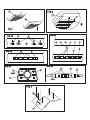
Il filtro può essere rimosso semplicemente tirando i due pomelli verso il basso (Fig. 2/2).Per
alcuni modelli dotati di filtro carbone come in Fig.7/1, il filtro può essere rimosso
esercitando una leggera pressione sugli agganci, ruotandolo poi verso il basso (Fig.8).
Filtro per grassi
Assorbe le particelle di grasso in sospensione nei vapori, proteggendo la cucina ed i mobili
dai residui di sostanze grasse. Va lavato ogni 10 - 15 gg. (in condizioni normali di esercizio)
immergendolo in soluzione sgrassante o mettendolo in lavastoviglie. Attenzione durante
tale operazione a non danneggiare il filtro urtandolo o schiacciandolo dato che è costituito
da più strati in lega leggera. Il filtro alluminio si può scurire; tale effetto non influisce
sull’efficacia del filtro, ma potrebbe migliorare le prestazioni dello stesso.
Sostituzione o pulizia
É sufficiente tirare la maniglia verso il retro, quindi procedere alla pulizia di quest'ultimo
e ripetere l'operazione in senso contrario (Fig. 1/1). Per rimuovere il filtro alluminio (Fig.
1/2), prendere il filtro dalla linguetta d'apertura, piegarla verso di se ed abbassare il filtro
in avanti, ripetere l'operazione in senso contrario per rimetterlo.
GB
Introduction
These instructions are designed to tell you of the various technical details of your
cooker hood and to make you familiar with its use. Since these instructions cover more
than one type of hood within the same series, it may be that reference is made to
components that do not form part of the hood that you are installing. The hood may
be used as an exhaust or filter hood. If evacuation is available (exhaust duct or air
flue) we recommend using the hood in the exhaust version to discharge all the kitchen
vapors and odors out-doors. Fittings can vary from country to country. We reserve
the right to modify the product without any notice always with the aim of improvements
and in compliance with the relevant norm.
Suggestions for using the hood in exhaust position
When an exhaust hood and a heat source requiring ambient air (e.g. gas, oil, coal
stoves, etc.) are used at the same time, attention is required because the air necessary
for combustion is exhausted from the room through the hood and this creates
depression. There is no such danger when the maximum depression in the room is 0,04
mbar. In this condition no exhaust gas from the heat source is piped. To assure this
condition, make openings in the room which cannot be closed (doors, windows, etc.
are not sufficient) and through which the air necessary for combustion can freely flow.
Note:—All the exhaust ductwork in the apartment or house should be studied. In case
of doubts, get advice or authorization from the person or agency responsible for the
building. When using gas burners, gas ovens, etc. as well as when using the hood
in the filter version, these precautions are not necessary. N.B. The efficiency of the
exhaust hood decreases as the length of the ducts and number of elbows increase.
When using the exhaust version, follow these rules: Do not connect the exhaust hood
to chimneys, flues, and air ducts serving the room. Before venting into exhaust flues
and ducts no longer in use, ask for the approval of the person or agency responsible
for the building. The evacuated air must not be let into a warm air duct. For the
evacuation of the exhausted air please note ufficial instructions.
Installation
The hood must be mounted over the center of the cooking area. The minimum distances
between the cooking area and the underpart of the hood are 650 mm.
N.B. The distances, however, are subject to the safety rules in effect in the various
countries.
Warning: If the room contains a flued fuel burning appliance which is not of the "balance
flue" type make sure these is an adequate air inlet to the room at all times so that fumes
are not drawn down the flue. Before drilling the wall make sure that no pipes or cables
will be damaged. If there is no outer waste-pipe for the exhaust version, an air outlet
with a diameter of Ø160mm, in case you use the spigot reduction (Fig.6/H) you need
an exhaust outlet of 130mm.
Attention: Take attention that the wallwill support the weight of the cookerhood (about
30 Kg). The screws supplied with this rangehood are designed for fixing to reinforced
concrete, masonry walls or hollow building blocks.
Wall fixing of the cooker hood
1) Set the distance between the cooker hob and the hood (Pict. 5).
2) If your hood is fitted with a metal carbon filter frame the mounting operation can
be made more easily by removing it by means of the screws (Pict. 2/1) before
beginning to work. The frame must be remounted when the operation is finished.
3) Join the two parts of the spigot (Pict. 6/H) and fix it to the upper part of the motor
group (Pict. 6/L) by means of the 4 screws (Pict. 6/I).
4) Drill the holes into the wall (Pict. 6/N) at the right distance showen here after, and
fix the cookerhood (Pict. 5).
5) For a correct installation the hood is provided (in the rear side of its body) with one
or two holes 8 mm diam. into which one or two wall fixing screws must be inserted
(Pict. 6/O).
6) For the exhaust version, please connect the flange to an outlet ducting of 125 mm
diameter (Pict. 6/F). If the hood is in recirculating version the flange must be fixed
to the connection piece, which is provided (Pict. 6/G).
Insure that all parts are properly fixed and that it is impossible to touch moving
parts.
N.B.: When using a 150mm air outlet, do not fasten the air outlet pipe with the screws,
as this might cause the metal valve to malfunction.
N.B.: In the case of recirculation fitting, join the flange and the T joint provided with
2 screws at the point marked with a line on the flange; this must all be done before
fixing the hood to the wall.
Installation of the pipes (valid for exhaust or filter version)
1) Fix the bracket (Pict. 6/C) with 2 plugs and screws (Pict. 6/A) in the required hight
for the pipe.
2) Screw the short pipe (Pict. 6/D) with 2 screws on the bracket (Pict. 6/B).
3) Insert the 2 nuts in the holes on the lower part of the long pipe. Put the long pipe
over the short one (Pict. 6/E) by pulling a part the laterals of the pipe.
4) Fix the long pipe with 2 screws on the hood (Pict. 6/Q).
Attention: The panel should be fitted (if supplied) over the body after installation and
fixed from the outside using the special screws, washer and cover provided (Fig. 4/
3). Some models could be supplied only with 2 external and 2 internal fixingpoints with
relevants nuts (Fig. 4/4). The crystal cover panels are only fixed from the outside.
Electric connection
Make sure the supply voltage ratings correspond with those stated on the appliance
data plate.
Attention: if the appliance is not provided with a plug or cannot be easily connected
to a wall socket, then the electrical circuit must incorporate a circuit breaker having
at least a 3 mm separation between contacts. If the appliance is provided with a supply
cord and plug, the appliances must be positioned so that the plug is accessible.
Attention: if there are three wires in the electrical supply cable they must be connected
as follows:
green/yellow = ground — blue = neutral — brown = line
Important: the hood manufacturer will not be responsible for any damage or loss
caused by failure to observe these instructions.
Important: a damaged power supply cord must be replaced by the service.
Using the cooker hood
The cooker hood should be switched on either before or at the same as cooking or
frying commences. The grease and carbon filters are more effective if the fan is not
switched off immediately after cooking or frying is completed, but only after a period
of some 20-30 minutes. Before using the cooker hood please ensure that all plastic
films like on metal grease filter an stainless steel ducting are removed.
User instructions
The cooker hood could be supplied with different operation panels (Fig. 3A-3B-3C) that
works in the following way:
Mechanical Switches (slide or pushbutton-Fig.3A)
1 - Speed Switch2 - Light Switch
Back Lit Switches HR (Fig.3B)
- Main Switch 1-2-3 Speed Switches
2 - Light Switch
The Timer will run if any speed switch is pushed for more than 3 seconds and will stop
running the cooker hood after 5 minutes.
Multicolour Switches HI-HC (Fig.3C)
1 - Speed Switches 2 - Light Switch 3 - Timer
The Timer will run if the timer switch is pushed and will stop running the cooker hood
after 5 minutes.
Silicon Switches (Fig.3D-E)
FIG.3D
+/- Speed Selector 2 – Light Switch 1 – ON/OFF Switch 3 – Display
The ON/OFF button switch on or off the hood. When the unit is switch OFF and the button
will be pressed for more than 2 seconds the motor will start in the last selected speed.
When the unit is switch ON and the button will be pressed for more than 2 seconds the
Timer will be activated. After 5 minutes the motor will switch OFF, during that time in the
display is blinking the selected speed.
With the button +/- can be changed the speed. When the unit is switch OFF and the button
- (minus) will be pressed in the display indicate the saturation of the grease filter. When
the unit is switch ON and the button + (plus) will be pressed for more than 2 seconds
it set the motor into the intensive speed. After 5 Minutes the motor return into the original
speed, during that time in the display is blinking the maximum speed.
FIG.3E
Each button is illuminated during it’s function by a blue LED.
2 – Light Switch 3 - Booster 1 – Speed Switch
The Booster button sets the hood for 5 minutes into the maximum speed and than turn
back into the before chosen speed. If any speed button will be pushed for more than
2 seconds the speed will be temporised for 5 minutes and than the unit switch-off
completely.
Operation light and function of saturation indication for the grease filters
Switches Fig.3B- The saturation of the grease filter will be indicated automatically after
20 hours by means with flashing of the running speed of the cooker hood. That mean
the grease filter should be cleaned or eventual changed.
It is as well possible to select manual the degree of saturation. By switch off cooker
hood and pushing the bottoms 1 and 3 temporary for more than 2 seconds:
- No flashing light of the bottom: less than 6 working hours
- Flashing light of bottom 1: between 6 and 12 working hours
- Flashing light of bottom 1 and 2: between 12 and 18 working hours
- Flashing light of bottom 1, 2 and 3: more than 18 working hours
After you have cleaned or eventual changed the grease filter you should reset the timer
by means pushing the main switch for more than 2 seconds. If the Timer will not by
reset manual the electronic will reset after 15 minutes automatically the Timer.
If your cooker hood is supplied with a charcoal filter and is running in the filtering method
the saturation of the charcoal filter will be indicated. After 120 hours all buttons except
the main switch will flashing and the charcoal filter should be replaced.
It is as well possible to select manual the degree of saturation. By switch off cooker
hood and pushing the bottoms 2 and 3 temporary for more than 2 seconds:
- No flashing light of the bottom: less than 30 working hours
- Flashing light of bottom 1: between 30 and 60 working hours
- Flashing light of bottom 1 and 2: between 60 and 110 working hours
- Flashing light of bottom 1, 2 and 3: more than 110 working hours
After you have replaced the charcoal filter you should reset the timer by means pushing
the main switch for more than 2 seconds. If the Timer will not by reset manual the
electronic will reset after 15 minutes automatically the Timer.
Switches Fig.3C - The saturation of the grease filter will be indicated by the operation
LED. By switch off cooker hood and pushing the bottom T the operation LED will indicate
different colours with following meanings:
Green Light: less than 6 working hours
Yellow Light: between 6 and 12 working hours
Red Light: more than 12 working hours (the grease filter should be cleaned or eventual
changed)
Switches Fig.3D - By switch off cooker hood and pushing the button - (minus) the display
will indicate the saturation of the grease filter:
- 1 - operation time between 5 and 10 hours
- 2 - operation time between 10 and 15 hours
- 3 - operation time between 15 and 20 hours
- 4 - operation time between 20 and 25 hours
- 5 - operation time between 25 and 30 hours
- 6 - more than 30 hours
Each time you switch off the hood the saturation of the grease filter will shown for 5
seconds.
After you have cleaned or eventual changed the grease filter you should reset the
timer by means pushing the button - (minus) for more than 5 seconds.
Switches Fig.3E - The saturation of the grease filter will be indicated by the
operation LED. By switch off cooker hood and pushing the Booster button (Fig.3/3E)
the operation LED will indicate the saturation of the grease filter with following
meanings:
- illumination of the button ON/OFF: less than 6 working hours
- illumination of the button 2: between 6 and 18 working hours
- illumination of the button 3: more than 18 working hours
Each time you switch off the hood the saturation of the grease filter will shown for 5
seconds.
After you have cleaned or eventual changed the grease filter you should reset the timer
by means pushing the Booster button for more than 5 seconds.

Setting from Exhaust method into Filtering method (only for model HR - Fig.3B)
To get an efficiency aspiration the cooker hood could work in 2 different methods -
Exhaust / Filtering. By setting the cooker hood into the proper method the electronic
will adjust automatically the fan speed to the air resistance of the charcoal filter.
Exhaust Method: By switch off cooker hood and pushing the bottom 1 for more than
3 seconds the cooker hood will set to the exhaust method - confirm by flashing all
buttons for 4 times.
Filtering Method: By switch off cooker hood and pushing the bottom 2 for more than
3 seconds the cooker hood will set to the filtering method - confirm by flashing all buttons
for 8 times.
Note: The cooker hood is set from the factory into the Exhaust method.
Lamp Replacement
When the tubolar neon lamps need to be replaced this must only be done by
a competent electrician because especiale tool is required. To changes low
energy neon lamps and incandescent bulbs please work from outside of the hood
means to pull off the lamp diffuser. If it has a halogen lamp look out not to touch
it with your hands when you replace it. Use a dry and not greasy protection (for
example a cloth) in order to avoid a direct contact with skin which could make
the lamp break. Never use lamps with a wattage higher than the one shown on
the label inside the hood.
Safety rules
Do not do any flambe cooking underneath the hood. When frying, never leave
the pan alone because the cooking oil could flare up. Clean all the surfaces
frequently to avoid danger of fire. This can be done with a cloth or/and with a
brush drenched with denatured alcohol or with any other similar substances,
except for the button area (Fig. 3)and lamp diffusor. It is also important to remove
and clean or substitute frequently the filter installed in the hood. This appliance
is not intended for use by small children or infirm persons without supervision.Young
children should be supervised to ensure that they do not play with the appliance.
Maintenance
NOTE: Prior to any maintenance, switch off and disconnect from electrical supply.
1) Under normal cooking conditions the grease filter should be cleaned every
10-15 days in hot water, to which a suitable detergent has been added. For
reasons of efficiency and safety regular cleaning is advised. The grease filter
may be subject to a small amount of shrinkage initially.
2) The outer casing of the Cooker Hood should be cleaned with a damp cloth.
3) The effective life of the carbon filter will naturally depend on the frequency
and type of cooking fumes to which it is subject. As general guide we suggest
that a replacement is fitted at least every 12 months.
4) Once a year, (more frequently with heavy usage), call a serviceman to clean
the fan and air ducts to prevent build-up of flammable fat deposits.
The carbon filter
When a carbon filter is fitted, the air that is sucked in is additionally cleaned by the
active carbon particles within the filter. This filter cannot be cleaned and so needs
to be replaced from time to time, approximately every six months, depending on how
frequently the hood is in use.
Replacing the active carbon filter
(only for recirculation hoods)
The filter can be easily removed by pulling downwards the two knobs (Pict. 2/2).
Some cooker hoods are supplied with the charcoal filter as in Fig. 7/1, to remove the
filter push the latches and pull the filter down (Fig. 8)
Grease filter
This absorbs vapor-suspended grease particles and protects the kitchen and furniture
from greasy residues. The filter should be washed every 10 to 15 days (in normal
operating conditions). Dip the filter into a de-greaser solution or put it in the dish washer.
Make sure not to damage the filter, which is made of several layers of thin alloy, by
hitting or crushing it. The aluminium filter will may change colour, that will have no
influence of the efficiency of the filter, may it will improve it.
Replacing or cleaning the filters
Just push the handle towards the rear, proceed with the cleaning and repeat the
operation counterclockwise (Pict. 1/1). To remove the aluminuim grease filter (Pict.
1/2), grab the opening tongue at the filter, pull it in your direction and move the filter
downwards. To reinstall it operate reversed.
Safety Requirements
Exhaust air must not be discharged into any chimney, or flue which may carry
combustion products from other sources. In addition, exhaust air must not be
discharged into a wall cavity unless designed for the purpose. Note instructions
for cleaning fan as note «4» on «MAINTENANCE». Moreover it is important to
clean regularly each filter of the hood or replace it .ATTENTION: THE RANGEHOOD
IS DESIGNED FOR INDOOR USE ONLY. UNDER NO CIRCUMSTANCES SHOULD
THIS UNIT BE INSTALLED IN OUTDOOR CONDITION OR OVER A BARBECUE.
F
Introduction
La présente notice a pour but de vous faire connaître les différents équipements
techniques de votre appareil et de vous familiariser avec son utilisation. Cette notice
s’applique à plusieurs modèles de ce type de hotte. Il se peut donc qu’elle mentionne
des éléments de commande dont votre appareil n’est pas doué. La hotte est utilisable
soit en version aspirante soit filtrante. En cas de possibilité d’évacuation (tuyau de
décharge ou conduit d’aération) il est conseillé d’employer la hotte en version aspirante
pour permettre l’évacuation à l’extérieur des vapeurs et des odeurs qui se créent dans
la cuisine. Les accessoires peuvent changer selon les pays. Nous nous reservons
de modifier le produit sans préais toujours dans la prospective d'une amélioration et
dans le respect des normatives.
Normes pour l’emploi de la hotte à la position aspirante
Quand, avec la hotte aspirante, il fonctionne aussi une source de chaleur qui a besoin
de l’air du milieu (chaudière à gaz, huile ou charbon etc) il faut faire attention car à
l’aide de la hotte on aspire du milieu l’air dont on a besoin pour la combustion, en créant
une dépression à une valeur de 0,04 mbar, à ces conditions, on évite l’aspiration des
gaz de décharge de la source de chaleur. Tel résultat est obtenu en effectuant dans
le milieu des ouvertures qui ne peuvent pas être obstruées (il ne s’agit ni de portes
ni de fenêtres) et dans lesquelles puisse entrer l’air nécessaire à la combustion.
N.B. Pour donner un avis il faut considérer le conduit de décharge prévu dans
l’appartement. En cas de doute il faut se faire conseiller ou se faire donner l’autorisation
par le responsable de l’édifice. Pour l’emploi des cuisinières à gaz four etc. et l’emploi
de la hotte à la position filtrante ces précautions ne sont pas nécessaires.
N.B. L’efficacité de la hotte aspirante est d’autant plus grande que le tuyau
d’évacuation est court et le nombre de coudes réduits. En version aspirante il faut
observer les indications suivantes. Pour la connexion de la hotte aspirante, il est
interdit de relier la décharge à des conduits de fumée, canaux de décharge ou
cheminées pour l’aération du milieu. Avec une décharge dans les cheminées hors
fonction il est conseillé d’avoir l’autorisation du responsable de l’édifice. L’air ne doit
pas être conduit vers une entrée où circule l’air chaud. Pour l’évacuation de l’air aspiré
il faut observer les prescriptions requises.
Montage - Pose de l'appareil
La hotte doit être fixée directement au centre du plan de cuisson. La distance minimum
entre le plan de cuisson et la surface inférieure de la hotte doit être de 650 mm.
N.B. Ces distances sont de toute façon réglées par les normatives de sécurité en vigueur
dans les différents pays.
Avant de perçer le mur faire attention à ne pas endommager aucune tuyauterie. En
cas d’absence de tuyau de déchargement à l’extérieur pour la version aspirante, il
faudra effectuer une sortie air sur le mur du diamètre de Ø160mm, dans le cas où on
utilise une réduction de la bride (Fig.6/H), il faudra effectuer un orifice ayant un diamètre
de 130mm. S’assurer que le mur supporte le poids de la hotte (poids de 30 Kg environ).
La confection des vis est appropriée pour la fixation sur béton armét, briques et brique
creuse.
Montage de la hotte au mur
1) Définir la distance entre la hotte et le plan de cuisson (Fig. 5).
2) Afin de faciliter le montage, si votre hotte a un cadre filtres charbon en métal. l'enlever
avant de commencer le montage, à l'aide des vis (Fig. 2/1). Ensuite remonter le
cadre.
3) Rènuir les deux parties de la buse (Fig. 6/H) et appliquer cette dernière à la partie
supérieure du bloc moteur (Fig. 6/L), le tout à l'aide des 4 vis (Fig. 6/I).
4) Faire les trous au mur pour le fixage de l'ensemble moteur-hotte (Fig. 6/N) à la juste
distance du plan de cuisson comme en annexe. Ensuite accrocher la hotte au mur
(Fig. 6).
5) Pour une installation correcte, la hotte a un ou deux trous de 8 mm. diamètre (sur
la partie postérieure du logement) où doivent être introduitcs une ou deux vis pour
le blocage au mur (Fig. 6/O).
6) Pour la hotte en version aspirante relier à la collerette un tuyau de sortie d'air Ø
125 mm (Fig. 6/F). Pour la hotte en version filtrante relier à la collerette le raccord
fourni (Fig. 6/G). Veuillez Vous assurer que toutes les parties soient bien fixées
et que les parties en mouvement soient bien protégées.
N.B.: En cas d’évacuation de l’air à 150 mm., il ne faut pas fixer le tuyau d’évacuation
de l’air au moyen de vis, afin d’éviter tout risque de fonctionnement incorrect de la
soupape en métal.
N.B.: En cas de connexion filtrante, il faudra relier la bride et le raccord en T fournis
avec l’appareil au moyen de deux vis, au point indiqué sur la bride par une ligne; ces
opérations devront être effectuées avant de monter la hotte contre le mur.
Montage des tubes
(Valable soit pour la version aspirante que filtrante)
1) Fixer la barre au mur (Fig. 6/C) selon la hauteur des tubes désirée et à l'aide de
2 vis avec tasseaux (Fig. 6/A).
2) Fixer le tube court (Fig. 6/D) à la barre à l'aide des 2 vis (Fig. 6/B).
3) Appliquer du devant le tube long (Fig. 6/E) en ouvrant légerement les 2 parties
latérales.
4) Fixer la hotte à l'aide des 2 vis en agissant de l'intérieur du tube long (Fig. 6/Q),
après avoir placé les ecrous recouverts.
Attention: Monter le panneau au-dessus (si fourni) de la coque installée précédemment
et le fixer de l’extérieur grâce aux sous-vis spéciales, les vis et le bouchon sont fournis
avec la hotte (Fig. 4/3). Certains modèles pourraient avoir uniquement deux points de
fixage de l'extérieur et deux de l'intérieur avec les écrous en dotation (Fig. 4/4). La
fixation des panneaux de couverture en cristal ne peut être faite que de l'extérieur.
Connexion électrique
Contrôler que les valeurs de la tension d’alimentation correspondent à celles reportées
sur l’étiquette de fonctionnement de l’appareil.
Attention: si l’appareil n’a pas de fiche il ne peut pas être relié facilement à une prise
de courant, pour l’installation fixe il faut prévoir un dispositif de séparation qui assure
l’omnipolaire déconnexion du réseau avec une distance d’ouverture des contacts d’au
moins 3mm. Si l’appareil a en dotation la fiche, cette dernière doit être accessible après
le montage de l’appareil.
Attention: si l’appareil présente 3 fils dans le cable d’alimentation, ils doivent être reliés
ainsi:
Vert-jaune = terre — bleu = neutre — marron = tension
NB: La maison productrice décline toutes responsabilités pour inconvenients
causés par la négligence de la sudite disposition. N.B. Pour changer le câble
alimentation endommagé , appeler le Service Après Vente.
Instructions d'emploi
La hotte doit être mise en marche au plus tard au début de la cuisson ou du rôtissage.
Vous augmenterez l’efficacité du filtre antigraisse et du filtre antiodeurs en arrêtant
la hotte seulement 20 à 30 minutes après la fin de cuisson. Avant de mettre la hotte
en fonction, retirer toutes les pellicules de protection, par exemple celles qui se
trouvent sur les filtres anti-graisse en aluminium ou sur les tubes en acier inox.
Fonctionnement de la hotte
La hotte a de différents types de commandes (Fig.3A-B-C)selon le modèle:
1. Interrupteur vitesse 2. Interrupteur lumière
Certains modèles ont un bouton T-Fonction Timer arrêt à une vitesse quelconque et
visualisation état des filtres (Fig.3/3C).Dans ce dernier cas, en poussant ce bouton
quand la hotte est en fonction, on allume un timer qui, après 5 minutes, éteint la hotte.
Si votre modèle a des boutons de commandes comme la Fig.3/B, en poussant un bouton
vitesse quelconque pour 3 secondes, à hotte allumée, on allume un timer qui, après
5 minutes éteignent la hotte.
Pour les hottes équipées de commandes comme illustré en figure Fig.3/D
+/- - commutateurs de vitesse 2 – interrupteurs lumières
1 - interrupteur allumage 3 - Display
La touche 1 allume et arrête la hotte et si on appuye dessus pendant plus de 2 secondes
lorsque la hotte éteinte, le moteur est porté à la dernière vitesse établie; si au contraire,
on appuye dessus pendant plus de 2 secondes avec la hotte allumée, on active l’arrêt
retardé: après 5 minutes le moteur s’éteint. Pendant le fonctionnement, le numéro de
la vitesse établie clignote sur le display.
Avec les touches +/- (plus/moins), on varie la vitesse. En appuyant sur la touche – (moins)
lorsque la hotte est éteinte, l’état de saturation des filtres à graisse est indiqué). En
appuyant sur la touche + (plus) pendant pllus de 2 secondes lorsque la hotte est allumée,
on porte le moteur à la vitesse maximum pendant 5 minutes, par après il retournera à
la vitesse établie initialement. Pendant le fonctionnent, le numéro de la vitesse maximum
clignote sur le display
Pour les hottes équipées de commandes comme illustré en figure Fig.3/E
Chaque touche, pendant le fonctionnement, est rétro-illuminée avec un LED bleu.
1 – commutateur de vitesse 2 – interrupteur lumière 3 - Booster
La touche Booster a comme fonction de temporiser: en l’appuyant, le moteur est porté
à une vitesse maximum pendant 5 minutes, ensuite, on retourne à la vitesse initiale,
celle qui a été établie précédemment. En appuyant sur n’importe quel commutateur de
vitesse pour plus de 2 secondes, la vitesse sera temporisée pendant 5 minutes, ensuite
la hotte s’éteint complètement..
Visualisation etat des filtres (disponible uniquement pour certaines versions)
Page is loading ...
Page is loading ...
Page is loading ...
Page is loading ...
Page is loading ...
Page is loading ...
-
 1
1
-
 2
2
-
 3
3
-
 4
4
-
 5
5
-
 6
6
-
 7
7
-
 8
8
-
 9
9
-
 10
10
-
 11
11
-
 12
12


Turboair ISCHIA IX/A/60 User manual
- Category
- Cooker hoods
- Type
- User manual
- This manual is also suitable for
Ask a question and I''ll find the answer in the document
Finding information in a document is now easier with AI
in other languages
- italiano: Turboair ISCHIA IX/A/60 Manuale utente
- français: Turboair ISCHIA IX/A/60 Manuel utilisateur
- español: Turboair ISCHIA IX/A/60 Manual de usuario
- Deutsch: Turboair ISCHIA IX/A/60 Benutzerhandbuch
- русский: Turboair ISCHIA IX/A/60 Руководство пользователя
- português: Turboair ISCHIA IX/A/60 Manual do usuário
Other documents
-
Alno AE 9017 E User manual
-
-
Vinsetto 921-605V00CG User guide
-
Whirlpool SCHLC 9.8 LAI User guide
-
Bertazzoni K36 HER X Owner's manual
-
-
Best CK800 User manual
-
-
-
ROSIERES RHT6300LIN User manual