Page is loading ...

Chromalox
®
DIVISION
4
SECTION
HB
SALES
REFERENCE
DATE
SERVICE REFERENCE
Installation Instructions
PM400-2
161-049691-001
MARCH, 1999
(Supersedes PM400-1)
© 2010 Chromalox, Inc.
GENERAL
WARNING: This heater is not intended for use in
hazardous atmospheres where flammable vapors,
gases, liquids, or other combustible atmospheres
are present as defined in the National Electrical
Code. Failure to comply can result in explosion or
fire.
1. Heater Construction Characteristics —
A. One-piece stainless steel clamping band.
B. Two (2) rust-resisting chrome steel sheath strip heater ele-
ments.
C. Heavy construction of clamp and quick-connect allen head
bolt allow firm grip on heaters and tight heater fit to pipe
or barrel configuration.
2. WARNING: Hazard of heater failure. Pipe or barrel
surface temperature not to exceed 800˚F.
3. Heater bands may be used individually or in multiples spaced
1/4” apart.
4. WARNING: Users should install adequate controls
and safety devices with their electric heating
equipment. Where consequences of failure may be
severe, back-up controls are essential. Although
the safety of the installation is the responsibility of
the user, Chromalox will be glad to make equip-
ment recommendations.
Type HB Heater Bands
for Barrel or Surface Temperatures up to 800˚F
Model PCN Volts Watts W/In
2
Amperes
Barrel Diameter Wt
(In.) (Lbs.)
HB-5075 273631 240 750 50 3.1 5 1.5
HB-5080 273287 240 800 48 3.3 5-1/4 1.75
HB-5460 272760 240 600 33 2.5 5-1/2 1.75
HB-5415 273463 240 1500 82 6.3 5-1/2 1.75
HB-6040 269149 240 400 20 1.7 6 2
HB-6075 268998 240 750 38 3.1 6 2
HB-6410 269464 240 1000 48 4.2 6-1/2 2
HB-7010 273623 240 1000 43 4.2 7 2
HB-7715 273586 240 1500 53 6.3 7-1/8 2.25
HB-7412 273578 240 1250 48 5.2 7-1/2 2.25
HB-7490 269157 240 900 35 3.8 7-1/2 2.25
HB-8013 269000 240 900 30 3.8 8 2
HB-8014 273599 240 1400 50 5.8 8 2.25
HB-8415 269886 240 1565 53 6.5 8-1/2 2.3
HB-9015 269018 240 1100 33 4.6 9 2.5
HB-9217 272073 240 1710 53 7.1 9-1/4 2.5
HB-9413 269165 240 1300 35 5.4 9-1/2 2.75
HB-9416 273640 240 1600 45 6.7 9-1/2 2.75
HB-1018 269878 240 1800 48 7.5 10 3
HB-10226 273615 240 2600 68 10.8 10-1/4 3
HB-10415 269026 240 1200 30 5.0 10-1/2 3
HB-1120 272305 240 2025 48 8.4 11 3.25
HB-11412 260034 240 1200 28 5.0 11-1/2 3.25
HB-11417 273711 240 1700 38 7.1 11-1/2 3.25
HB-12416 269042 240 1500 30 6.3 12-1/2 3.5
HB-13418 269050 240 1800 38 7.5 13-1/2 3.75
HB-1412 269130 240 1200 23 5.0 14 3.9
HB-1425 269069 240 2500 45 10.4 14 3.9
HB-15425 269077 240 2500 40 10.4 15-1/2 4
HB-1725 263986 240 2500 38 10.4 17 4.2
HB-17425 263994 240 2500 38 10.4 17-1/2 4.3
HB-2030 264006 240 2500 38 12.5 20 4.5
Specifications — Table A
1/4” spacing between
multiples.
1-1/2” W
Type HB

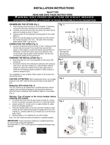
INSTALLATION
WARNING: Hazard of Electric Shock. Disconnect all
power before installing heater.
1. Position slots in clamping band over terminal posts on heating
elements. Note: Terminal hardware must be removed to allow
clamping band slots to fit over terminal posts (Figure 1).
2. When heater band is correctly placed in the desired location,
compress ends of band together and insert bolt through non-
threaded trunnion socket and then into opposite threaded sock-
et. Hand tighten (Figure 2).
3. Turn Allen head bolt with 7/32” Allen wrench to draw heater
band tight on cylinder. Ensure that there is good contact
between heating element and cylinder and that there is electri-
cal clearance between the heater terminals and the clamping
band (Figure 1).
4. DANGER: Hazard of Fire. Since these heaters are capa-
ble of developing high temperatures, extreme care should be
taken to:
A. Avoid installing heaters in an atmosphere containing com-
bustible gases and vapor.
B. Avoid contact between heater and combustible material.
C. Keep combustible materials far enough away to be free of
effects of high temperature.
Figure 1
Figure 2 Figure 3
WIRING
WARNING: Hazard of Electric Shock. Any installation
involving electric heaters must be effectively ground-
ed in accordance with the National Electical Code to
eliminate shock hazard.
1. Rough-in Wiring — Wiring to heater should be to the volt-
age specified on heater band and in accordance with local and
National Electrical codes by a qualified person. As a guide in
determining line wire sizes see Amperes in Specifications
Table A on page 1. WARNING: Use copper conduc-
tors only.
2. Assemble terminal hardware and wiring in the order shown in
Figure 5.
3. Protection with proper size fuses and breakers is important to
minimize hazards.
WARNING: Do not exceed 25 inch pounds of torque
when tightening the hex nuts on the heater termi-
nals. Excessive torque will result in stripping the
terminals from the refractory of the heating ele-
ment.
4. For rated output for heater band, connect heating elements in
parallel. 240V elements to be run on 480V should be connect-
ed in series. When element wattages are not equal, heaters
must not be connected in series.
TESTING
DANGER: Hazard of Electric Shock or Burns. Avoid
contact of hot surfaces and live electrical terminals
during this adjustment.
1. Energize the heater and check for hot spots after the heater has
reached operating temperature. These can be identified as
bright red areas on the heating element or dark brown areas on
the clamping band. If hot spots are encountered, place a wood-
en block on the affected area and tap lightly with a hammer to
bring the heater in contact with the pipe or barrel surface.
2. It’s good practice to check the tightness of the clamping
band after a few hours at operation temperature. Chromalox
HTRC (Heat Trans-fer and Release Coating) is also available
for high temperature applications.
Figure 4
MAINTENANCE
WARNING: Hazard of Severe Shock. Disconnect all
power to heater before servicing or replacing
heaters.
1. For longer heater life, maintain good contact between heater
and work cylinder by periodically checking clamping band
tightness.
2. Make certain that both terminals and band are free from con-
tact with oil, liquids or other foreign matter. Such contaminants
can cause heater failures.
3. Check for loose terminal connections and tighten if necessary.

RENEWAL PARTS IDENTIFICATION
Model Strip Heater Model Strip Heater P/N Clamping Band* P/N
HB-5075 PT8X354 286-117673-001 (2) 011-110109-056
HB-5080 PT8X320 286-117673-002 (2) 011-110109-001
HB-5460 PT10X303 286-117673-003 (2) 011-110109-002
HB-5414 PT10X321 286-117673-004 (2) 011-110109-002
HB-6040 PT10X151 286-117673-005 (2) 011-110109-004
HB-6075 PT10X152 286-117673-006 (2) 011-110109-004
HB-6410 PT12X316 286-117673-007 (2) 011-110109-006
HB-7010 PT12X353 286-117673-009 (2) 011-110109-008
HB-7490 PT14X295 286-117673-010 (2) 011-110109-010
HB-7412 PT12X348 286-117673-011 (2) 011-110109-010
HB-7715 PT14X349 286-117673-012 (2) 011-110109-059
HB-8013 PT14X194 286-117673-013 (2) 011-110109-011
HB-8014 PT14X350 286-117673-014 (2) 011-110109-011
HB-8415 PT15X325 286-117673-015 (2) 011-110109-012
HB-9015 PT15X195 286-117673-016 (2) 011-110109-014
HB-9217 PT15X324 286-117673-017 (2) 011-110109-015
HB-9413 PT16X167 286-117673-018 (2) 011-110109-016
HB-9416 PT15X355 286-117673-019 (2) 011-110109-016
HB-1018 PT16X326 286-117673-020 (2) 011-110109-018
HB-10226 PT16X352 286-117673-021 (2) 011-110109-019
HB-10415 PT18X196 286-117673-022 (2) 011-110109-020
HB-1120 PT19X323 286-117673-023 (2) 011-110109-022
HB-11412 PT19X132 286-117673-024 (2) 011-110109-024
HB-11417 PT19X322 286-117673-025 (2) 011-110109-024
HB-12416 PT20X279 286-117673-026 (2) 011-110109-026
HB-13418 PT20X150 286-117673-027 (2) 011-110109-028
HB-1412 PT23X277 286-117673-028 (2) 011-110109-030
HB-1425 PT23X156 286-117673-029 (2) 011-110109-030
HB-15425 PT25X191 286-117673-030 (2) 011-110109-033
HB-1725 PT26X142 286-117673-031 (2) 011-110109-038
HB-17425 PT26X199 286-117673-032 (2) 011-110109-040
HB-2030 PT33X193 286-117673-033 (2) 011-110109-045
1 1 2
*Includes allen head bolt.
Note: Number in ( ) indicates quantity of same part number used.
Hex Nut
Washer
Washer
Allen Head Bolt
Cup Washer
Hex Nut
Figure 5

2150 N. RULON WHITE BLVD., OGDEN, UT 84404
Phone: 1-800-368-2493 www.chromalox.com
Limited Warranty:
Please refer to the Chromalox limited warranty applicable to this product at
http://www.chromalox.com/customer-service/policies/termsofsale.aspx.
/