Page is loading ...

Model 7605 / Model 7606
Radiating Loop
&
Loop Sensor
User Manual
For MIL-STD-461D Tests
In Accordance With
Method RS101 of MIL-STD-462D

ETS-Lindgren L.P. reserves the right to make changes to any product described
herein in order to improve function, design, or for any other reason. Nothing
contained herein shall constitute ETS-Lindgren L.P. assuming any liability
whatsoever arising out of the application or use of any product or circuit
described herein. ETS-Lindgren L.P. does not convey any license under its
patent rights or the rights of others.
© Copyright 1999–2010 by ETS-Lindgren L.P. All Rights Reserved. No part
of this document may be copied by any means without written permission
from ETS-Lindgren L.P.
Trademarks used in this document: The ETS-Lindgren logo is a trademark of
ETS-Lindgren L.P.
Revision Record
MANUAL MODEL 7605/7606 MILSTD 461D RS101 | Part # 399222, Rev. B
Revision Description Date
A Initial Release April, 1999
B Rebrand July, 2010
ii |

Table of Contents
Notes, Cautions, and Warnings ................................................ v
About This Manual ................................................................... vii
1.0 Introduction .......................................................................... 9
About Model 7605 ........................................................................................ 10
About Model 7606 ........................................................................................ 10
References .................................................................................................. 11
ETS-Lindgren Product Information Bulletin ................................................. 12
2.0 Maintenance ....................................................................... 13
Annual Calibration ....................................................................................... 13
Service Procedures ..................................................................................... 13
3.0 Specifications ..................................................................... 15
Electrical Specifications ............................................................................... 15
Physical Specifications ................................................................................ 15
4.0 Theory of Operation ........................................................... 17
Schematic of 7605/7606 in Calibration Configuration .................................. 17
Model 7605 .................................................................................................. 18
Equation 1 ............................................................................................ 18
Equation 2 ............................................................................................ 18
Model 7606 .................................................................................................. 19
Equation 3 ............................................................................................ 19
Equation 4 ............................................................................................ 19
Equation 5 ............................................................................................ 20
Equation 6 ............................................................................................ 20
Equation 7 ............................................................................................ 20
Conversion Factors for Model 7606..................................................... 21
Equation 8 ............................................................................................ 22
5.0 MIL-STD-462D Method RS101 Testing ............................. 23
Operational Cautions ................................................................................... 23
Assembly for Calibration .............................................................................. 24
Method RS101 Calibration ........................................................................... 25
Required instrumentation ..................................................................... 25
| iii

About the Signal Source ...................................................................... 26
About the Measuring Instruments ........................................................ 27
About the Current Probe ...................................................................... 27
Calibration Steps ................................................................................. 28
Disassembly for Method RS101 Testing ..................................................... 29
Method RS101 Testing ................................................................................ 30
Start the EUT ....................................................................................... 31
Select Test Frequencies ...................................................................... 31
Equation 9 ................................................................................... 33
Testing the EUT ................................................................................... 34
Equation 10 ................................................................................. 34
Model 7606 Calibration Calculations ........................................................... 34
Calibration by Calculation .................................................................... 35
Equation 11 ................................................................................. 35
Equation 12 ................................................................................. 35
Equation 13 ................................................................................. 36
Equation 14 ................................................................................. 36
Traceability to NIST ............................................................................. 37
Appendix A: Warranty ............................................................. 39
iv |

Notes, Cautions, and Warnings
Note: Denotes helpful information intended to
provide tips for better use of the product.
Caution: Denotes a hazard. Failure to follow
instructions could result in minor personal injury
and/or property damage. Included text gives proper
procedures.
Warning: Denotes a hazard. Failure to follow
instructions could result in SEVERE personal injury
and/or property damage. Included text gives proper
procedures.
See the ETS-Lindgren Product Information Bulletin for safety,
regulatory, and other product marking information.
| v

This page intentionally left blank.
vi |

About This Manual
Numbers enclosed in square brackets correspond to the references
listed in References on page 11.
• This manual explains the theory of operation of the Model 7605
Radiating Loop and Model 7606 Radiating Sensor, and the use of the
set for MIL-STD-462D [1] electromagnetic interference (EMI) testing.
• The scope of this manual includes only the theory of operation,
calibration, and use of Model 7605 and Model 7606 for EMI testing in
accordance with Method RS101 [2] of MIL-STD-462D.
• The use of Model 7605 and Model 7606 for other purposes in
electromagnetic compatibility (EMC) testing is limited only by the
ingenuity of the user, but uses in addition to MIL-STD-462,
Method RS101 EMI testing are not included.
• The international system of units (SI) is used throughout this manual.
Refer to IEEE Std 268 [3] for correct abbreviations and their proper
use, and IEEE Std 260 [4] for the proper use of units with the decibel
symbol (dB).
• In general, definitions of EMC terms are contained in ANSI C63.14 [5]
and other electrical terms in IEEE Std 100 [6].
| vii

viii |
This page intentionally left blank.

1.0 Introduction
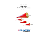
The ETS-Lindgren Model 7605 Radiating Loop and Model 7606 Radiating
Sensor are provided as a set, and are used together for the test equipment
calibration described in Method RS101 of MIL-STD-462D. Model 7605 is used
separately during susceptibility (immunity) testing of Equipment Under
Test (EUT).
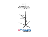
Use the included nylon bolt to connect the Model 7605 and
Model 7606 together. Do not use a metallic bolt or calibration will be
inaccurate.
Shown unassembled Shown assembled
Introduction | 9

About Model 7605
• Model 7605 is a 20-turn coil of AWG-12 enamel-insulated copper wire.
It is wound in a groove on a coil form made of a polytetrafluoroethylene
(PTFE) material. The average diameter of the coil is 12 cm (120 mm).
• The coil form is extended to provide a built-in 5-cm spacer to keep the
coil at the required distance from the EUT. A slot with a threaded
screw hole is cut into the end of the spacer to attach the Model 7606.
• The coil is used to expose EUT to magnetic fields in the range of 30 Hz
to 100 kHz. It produces a magnetic field that has a flux density of
9.5 x 10
7
picotesla per ampere (pT/A) of current flowing in it at an axial
distance of 5 cm (50 mm) from the center. In decibels, this is
160 dB(pT/A). The coil can carry 15 A rms (root mean square) of
alternating current with only ambient cooling.
About Model 7606
• Model 7606 is a 4-cm (40-mm) diameter, electrostatically-shielded loop
antenna with 51 turns of 7-strand AWG-41 litz wire.
• The Model 7606 is used to calibrate the Model 7605 and associated
instrumentation. It has a phenolic holder which mounts to the
Model 7605 to hold both windings parallel and coaxial to each other
with their centers precisely 5 cm apart. The holder of the Model 7606
has a 1/4–20 threaded hole to mount to a standard tripod.
• The Model 7606 is terminated in a BNC connector near the end of the
holder. For test setup calibration, the Model 7605 and Model 7606 are
fastened together with a 3/8–16 nylon bolt.
10 | Introduction

References
[1] MIL-STD-462D, 11 January 1993, Military Standard Measurements of
Electromagnetic Interference Characteristics.
[2] Method RS101, "Radiated Susceptibility, Magnetic Field, 30 Hz to
100 kHz," MIL-STD-462D, 11 January 1993, pp 103–108.
[3] IEEE Std 268–1992, American National Standard for Metric Practice.
(ANSI)
[4] IEEE Std 260–1978 (Reaffirmed 1985), IEEE Standard Letter Symbols
for Units of Measurement. (ANSI)
[5] ANSI C63.14–1992, American National Standard Dictionary for
Technologies of Electromagnetic Compatibility (EMC), Electromagnetic
Pulse (EMP), and Electrostatic Discharge (ESD).
[6] IEEE Std 100–1992, Standard Dictionary of Electrical and Electronics
Terms. (ANSI)
[7] Ramo, Simon, and John R. Whinnery, Fields and Waves in Modem
Radio, Second Edition, John Wiley & Sons, Inc. NY, 1953, (©General
Electric Company 1944, 1953), pp 90–91.
[8] Jasik, Henry, Editor, Antenna Engineering Handbook. McGraw-Hill, 1961,
p 6–2.
[9] MIL-STD-461D, 11 January 1993, Military Standard Requirements for the
Control of Electromagnetic Interference Emissions and Susceptibility,
pp 40–41.
[10] MRP-P 1990:8, Testing Visual Display Units, Draft, National Council for
Metrology and Testing, Sweden.
Introduction | 11

ETS-Lindgren Product Information Bulletin
See the ETS-Lindgren Product Information Bulletin included with your shipment
for the following:
• Warranty information
• Safety, regulatory, and other product marking information
• Steps to receive your shipment
• Steps to return a component for service
• ETS-Lindgren calibration service
• ETS-Lindgren contact information
12 | Introduction

2.0 Maintenance
Before performing any maintenance,
follow the safety information in the
ETS-Lindgren Product Information
Bulletin included with your shipment.
Maintenance of the Model 7605 and Model 7606 is limited to external
components such as cables or connectors. If you have any questions concerning
maintenance, contact ETS-Lindgren Customer Service.
Annual Calibration
See the Product Information Bulletin included with your shipment for information
on ETS-Lindgren calibration services.
Service Procedures
For the steps to return a system or system component to ETS-Lindgren for
service, see the Product Information Bulletin included with your shipment.
Maintenance | 13

This page intentionally left blank.
14 | Maintenance

3.0 Specifications
Electrical Specifications
Model 7605 Model 7606
Frequency Range: 30 Hz–100 kHz 30 Hz–100 kHz
Wire: AWG-12
Enameled Copper
7-41
Litz Copper
Number of Turns: 20 51
Maximum Input Current: 15 A Continuous NA
Connector: Banana Jack (Pair) Type BNC Female
Resistance of Winding
(Approximate):
40 mΩ 3.9 Ω
Inductance
(Approximate):
71.8 µH 175 µH
Physical Specifications
The windings on both models have square cross sections with dimensions of
approximately 12 mm for the Model 7605 Radiating Loop and approximately
3.175 mm for the Model 7606 Radiating Sensor.
Model 7605 Model 7606
Height: 5.89 cm (2.32 in) 13.46 cm (5.30 in)
Base Width: NA 5.08 cm (2.00 in)
Base Depth: NA 1.90 cm (0.75 in)
Mean Loop Diameter: 12.0 cm 4.0 cm
Specifications | 15

This page intentionally left blank.
16 | Specifications

4.0 Theory of Operation
Schematic of 7605/7606 in Calibration Configuration
The following illustration shows the Model 7605 Radiating Loop and the
Model 7606 Radiating Sensor as loops or coils separated by a calibration
distance of 5 cm.
Theory of Operation | 17

Model 7605
Model 7605 is used alone to produce an AC magnetic field to test Equipment
Under Test (EUT) for susceptibility (immunity) to magnetic fields in the frequency
range from 30 Hz to 100 kHz. It consists of 20 turns of AWG-12 enamel-insulated
copper wire close-wound with an average diameter of 12 cm. It is capable of
carrying 15 A rms, but if this level of coil current is sustained for long periods, the
coil will become warm. It has a coil resistance of approximately 40 mΩ and an
inductance of approximately 71.8 µH.
EQUATION 1
Equation 1 derived from [7] gives the relationship between coil current and
magnetic flux density.
Equation 1 may be simplified for computation as shown in equation 2.
EQUATION 2
18 | Theory of Operation

Model 7606
Model 7606 is used with Model 7605 to calibrate the 7605 and other
instrumentation used in tests. With 51 turns of wire in a 4-cm diameter loop, it
has an effective area of 640 cm
2
(an effective diameter of 28.6 cm), improving
the sensitivity of measurements with a given instrument by more than 30 dB over
a small, single-turn loop. The response is tabulated in the Conversion Factors for
Model 7606 table on page 21 (and is proportional to the frequency shown in
Figure RS101-1 in Method RS101 of MIL-STD-462D).
The voltage induced in the loop, e
i
, is proportional to the area of the loop, the
number of turns, the frequency, and the average flux density within the area of
the loop. Equation 3 derived from [8] gives this relationship.
EQUATION 3
For the Model 7606, the open-circuit loop-terminal induced voltage in microvolts
for a magnetic flux density in picotesla is given in equation 4.
EQUATION 4
The general equation for the conversion factor is given by equation 5 and
equation 6, and includes the effects of loop impedance and load impedance.
Theory of Operation | 19

EQUATION 5
EQUATION 6
For the Model 7606, equation 6 becomes equation 7.
EQUATION 7
The values in the following table were calculated from equation 5 and equation 7
using a 50 Ω load and a 600 Ω load. (These values are the same as in
Figure RS101-1 in MIL-STD-462D.)
20 | Theory of Operation
/