www.petsafe.net 19
The Power and Loop
Indicator Lights are off.
Check that the Power Adapter is plugged into the Fence Transmitter. •
Try plugging into another 120-volt outlet. •
If the lights still do not come on, the Fence Transmitter and/or Power Adapter •
needs to be replaced. Contact the Customer Care Center at 1-800-732-2677.
The Power Light is on,
the Loop Indicator Light
is off, and the Fence
Transmitter loop alarm
is sounding.
Make sure both ends of the Boundary Wire are plugged into Boundary Wire Terminals and •
that
1
⁄2 inch of the insulation is stripped so that the copper wire is exposed.
Perform the “Short Loop Test” (page 19) to determine if the Fence Transmitter needs to •
be replaced or if the Boundary Wire is broken.
If the Fence Transmitter is functioning properly, you have a break in your Boundary •
Wire. See the “Locating a Break in the Wire” (page 19) section in this guide.
The fuse blows when it is
replaced.
The Fence Transmitter and/or Power Adapter needs to be replaced. Contact the •
Customer Care Center at 1-800-732-2677.
Additional Information
The Boundary Wire is buried so that it is not accidentally tripped over or cut. Use care when using a weed •
eater or when digging near the Boundary Wire to prevent damage.
The system should only be used with healthy pets. Contact your veterinarian if you have concerns about the •
medical condition of your pet (medication, pregnant, heart conditions, etc.).
This system is not for vicious or aggressive pets. If your pet may pose a threat to others, • DO NOT USE THIS
SYSTEM. If you are unsure if your dog is aggressive, please consult your veterinarian or a certifi ed trainer.
The PetSafe•
®
Deluxe In-Ground Fence
™
is for residential use only.
The Static Correction will get your pet’s attention, but will not cause harm. It is designed to startle, not to punish. •
Test the Receiver Collar at least once a month to verify that it is functioning properly. Check that it activates at •
the Boundary Wire. Battery life depends upon how often the Receiver Collar is activated.
Remove the Receiver collar from your pet when indoors for the comfort of your pet.•
Never leave the Receiver Collar on your pet for more than 12 consecutive hours.•
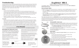
Short Loop Test
The Short Loop Test is a simple test to determine if each component (Fence Transmitter, Receiver Collar and
Boundary Wire) is functioning properly.
Disconnect the Boundary Wire and Ground Wire.1.
Cut approximately 10 feet of unused Boundary Wire and connect it to the Boundary Wire Terminals.2.
Spread the Boundary Wire out into a circle. Set the Boundary Control Switch to 3. B.
Set the Boundary Width Control knob to 10 and the Static Correction Level to level 2 or above.4.
If the Loop Indicator Light is not lit, then your Fence Transmitter is not functioning properly. Contact the 5.
Customer Care Center at 1-800-732-2677.
If the Loop Indicator Light is lit, disconnect one end of the Boundary Wire from the Boundary Wire Terminal.6.
If the loop alarm does not sound, the Fence Transmitter needs to be replaced. Contact the Customer Care 7.
Center at 1-800-732-2677.
If the loop alarm does sound, plug the Boundary Wire back into the Boundary Wire Terminal.8.
Hold the Test Light Contacts to the Receiver Contact Points. Hold the Receiver Collar next to the 10-foot 9.
length of Boundary Wire. The Receiver Collar should beep about one foot away from the Boundary Wire. The
Test Light should then fl ash as you hold the Receiver Collar closer to the Boundary Wire.
If Receiver Collar does not beep and the Test Light does not fl ash, replace the battery in the Receiver Collar. If 10.
it still does not beep and the Test Light does not fl ash, contact the Customer Care Center at 1-800-732-2677.
If the Receiver Collar beeps, there may be a complete or partial break in the Boundary Wire. See the “To 11.
Locate a Break in the Boundary Wire” section (page 19).
To Locate a Break in the Boundary Wire
Please follow these steps in determining where you have a break in your Boundary Wire:
Locate your original splice(s) and verify they have a good, solid connection.1.
Check your yard to determine any possible damage to the Boundary Wire (e.g. recent digging, aerating, 2.
rodent burrowing, or any other noticeable disturbance in your yard next to the Boundary Wire).