
USER’S MANUAL
Revision 1.0b
X8OBN-F Platform
with
X8OBN-F Baseboard
X8OBN-CPU CPU Board
X8OBN-BR1 Bridge Card

Manual Revision 1.0b
Release Date: April 6, 2011
Unless you request and receive written permission from Super Micro Computer, Inc., you may not
copy any part of this document.
Information in this document is subject to change without notice. Other products and companies
referred to herein are trademarks or registered trademarks of their respective companies or mark
holders.
Copyright © 2011 by Super Micro Computer, Inc.
All rights reserved.
Printed in the United States of America
The information in this User’s Manual has been carefully reviewed and is believed to be accurate.
The vendor assumes no responsibility for any inaccuracies that may be contained in this document,
and makes no commitment to update or to keep current the information in this manual, or to notify
any person or organization of the updates. Please Note: For the most up-to-date version of this
manual, please see our Website at www.supermicro.com.
Super Micro Computer, Inc. ("Supermicro") reserves the right to make changes to the product
described in this manual at any time and without notice. This product, including software and docu-
mentation, is the property of Supermicro and/or its licensors, and is supplied only under a license.
Any use or reproduction of this product is not allowed, except as expressly permitted by the terms
of said license.
IN NO EVENT WILL SUPER MICRO COMPUTER, INC. BE LIABLE FOR DIRECT, INDIRECT,
SPECIAL, INCIDENTAL, SPECULATIVE OR CONSEQUENTIAL DAMAGES ARISING FROM THE
USE OR INABILITY TO USE THIS PRODUCT OR DOCUMENTATION, EVEN IF ADVISED OF
THE POSSIBILITY OF SUCH DAMAGES. IN PARTICULAR, SUPER MICRO COMPUTER, INC.
SHALL NOT HAVE LIABILITY FOR ANY HARDWARE, SOFTWARE, OR DATA STORED OR USED
WITH THE PRODUCT, INCLUDING THE COSTS OF REPAIRING, REPLACING, INTEGRATING,
INSTALLING OR RECOVERING SUCH HARDWARE, SOFTWARE, OR DATA.
Any disputes arising between the manufacturer and the customer shall be governed by the laws of
Santa Clara County in the State of California, USA. The State of California, County of Santa Clara
shall be the exclusive venue for the resolution of any such disputes. Supermicro's total liability for
all claims will not exceed the price paid for the hardware product.
FCC Statement: This equipment has been tested and found to comply with the limits for a Class
A digital device pursuant to Part 15 of the FCC Rules. These limits are designed to provide
reasonable protection against harmful interference when the equipment is operated in a commercial
environment. This equipment generates, uses, and can radiate radio frequency energy and, if not
installed and used in accordance with the manufacturer’s instruction manual, may cause harmful
interference with radio communications. Operation of this equipment in a residential area is likely
to cause harmful interference, in which case you will be required to correct the interference at your
own expense.
California Best Management Practices Regulations for Perchlorate Materials: This Perchlorate
warning applies only to products containing CR (Manganese Dioxide) Lithium coin cells. “Perchlorate
Material-special handling may apply. See www.dtsc.ca.gov/hazardouswaste/perchlorate”.
WARNING: Handling of lead solder materials used in this
product may expose you to lead, a chemical known to
the State of California to cause birth defects and other
reproductive harm.

Preface
This manual is written for system integrators, PC technicians and
knowledgeable PC users. It provides information for the installation and use of the
X8OBN-F platform, which consists of the X8OBN Baseboard, the X8OBN-CPU
Board, and the X8OBN-BR1 Bridge Card.
About the X8OBN-F Platform
The X8OBN-F platform consists of the X8OBN Baseboard, the X8OBN-CPU CPU
Board, and the X8OBN-BR1 Bridge Card. Each X8OBN-CPU Board supports up to
two Intel 7500 Series processors and 16 DDR3 1066MHz memory modules. The
Intel Socket-LS processor offers Intel QuickPath Interconnect (QPI) Technology,
providing point-to-point system interface that replaces Front Side Bus technology.
The X8OBN-BR Bridge card provides connections between a pair of the CPU boards
installed on the X8OBN Baseboard. With support of Intel Turbo Boost Technology
and up to 80 CPU cores, the X8OBN-F platform offers substantial enhancement in
system performance for 4-way and 8-way servers. Please refer to our Website at
http://www.supermicro.com for processor and memory support updates. This prod-
uct is intended to be installed and serviced by professional technicians.
Manual Organization
Chapter 1 provides quick installation instructions.
Chapter 2 describes the features, specifi cations and performance of the X8OBN-F
baseboard, and provides detailed information on the 7500 chipset.
Chapter 3 provides hardware installation instructions. Read this chapter when in-
stalling the processor, memory modules and other hardware components into the
system. If you encounter any problems, see Chapter 4, which describes trouble-
shooting procedures for video, memory and system setup stored in CMOS.
Chapter 5 includes an introduction to the BIOS and provides detailed information
on running the CMOS Setup Utility.
Appendix A provides BIOS Error Beep Codes.
Appendix B lists software installation instructions.
Preface
iii

Conventions Used in this Manual
Pay special attention to the following symbols for proper baseboard installation and
to prevent damage to the system or injury to yourself:
Danger/Caution: Instructions to be strictly followed to prevent catastrophic
system failure or to avoid bodily injury,
Warning: Important information given to ensure proper system installation
or to prevent damage to the components,
Note: Additional information given to differentiate between various models
or to provide information for correct system setup.
iv
X8OBN-F Platform User’s Manual

Preface
v
Contacting Supermicro
Headquarters
Address: Super Micro Computer, Inc.
980 Rock Ave.
San Jose, CA 95131 U.S.A.
Tel: +1 (408) 503-8000
Fax: +1 (408) 503-8008
Email: [email protected] (General Information)
[email protected] (Technical Support)
Website: www.supermicro.com
Europe
Address: Super Micro Computer B.V.
Het Sterrenbeeld 28, 5215 ML
's-Hertogenbosch, The Netherlands
Tel: +31 (0) 73-6400390
Fax: +31 (0) 73-6416525
Email: [email protected] (General Information)
[email protected] (Technical Support)
[email protected] (Customer Support)
Asia-Pacifi c
Address: Super Micro Computer, Inc.
4F, No. 232-1, Liancheng Rd.
Chung-Ho 235, Taipei County
Taiwan, R.O.C.
Tel: +886-(2) 8226-3990
Fax: +886-(2) 8226-3991
Website: www.supermicro.com.tw
Technical Support:
Email: [email protected]
Tel: 886-2-8228-1366, ext.132 or 139

vi
X8OBN-F Platform User’s Manual
Table of Contents
Preface
Chapter 1 Quick Installation Guide
1-1 Preparation for Proper System Installation .....................................................1-1
Removing the Bridge Card from the Chassis ................................................. 1-1
Removing the CPU Board from the Chassis .................................................. 1-1
Attaching the Bridge Card to the Bridge Card Plate ......................................1-2
Attaching the CPU Board to the CPU Board Plate ........................................ 1-2
Installing the I/O Shield on the Rear Side of the Chassis ..............................1-3
1-2 Installing the CPU on the CPU Board ............................................................ 1-4
1-3 Installing the Memory Module on the CPU Board .......................................... 1-4
1-4 Installing the CPU Heatsink on the CPU Board .............................................1-5
1-5 Attaching the Air Shroud on the CPU Board ..................................................1-5
1-6 Installing the Baseboard into the Chassis ...................................................... 1-6
1-7 Installing the Populated CPU Board on the Baseboard ................................. 1-7
Installing the CPU Board (w/the CPU Board Plate Attached) on the Baseboard
........................................................................................................................ 1-7
1-8 Installing the Bridge Card between the CPU Boards ..................................... 1-8
1-9 Installing Internal Peripherals .......................................................................... 1-9
1-10 Installing External Peripherals ........................................................................ 1-9
Chapter 2 Overview
2-1 Overview .........................................................................................................2-1
2-2 Chipset Overview ..........................................................................................2-13
2-3 Special Features ........................................................................................... 2-14
2-4 PC Health Monitoring ....................................................................................2-14
2-5 ACPI Features ...............................................................................................2-15
2-6 Power Supply ................................................................................................ 2-15
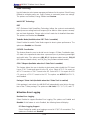
2-7 Super I/O .......................................................................................................2-16
2-8 Overview of the Nuvoton WPCM450R Controller ....................................... 2-16
Chapter 3 Installation
3-1 Static-Sensitive Devices .................................................................................. 3-1
3-2 Populating the CPU Board .............................................................................. 3-2
Installing a CPU on the CPU Board ............................................................... 3-2
Installing the CPU Heatsink on the CPU Board ............................................. 3-3
Installing Memory Modules on the CPU Board .............................................. 3-4
Removing Memory Modules ........................................................................... 3-4
3-3 Installing the Baseboard into the Chassis ...................................................... 3-5
3-4 Installing the Populated CPU Board on the Baseboard ................................. 3-6

vii
Table of Contents
3-5 Installing the Bridge Card between the CPU Boards ..................................... 3-7
3-6 Memory Support for the X8OBN-F Platform ...................................................3-8
3-7 Control Panel Connectors/I/O Ports..............................................................3-10
Back Panel Connectors/I/O Ports .................................................................3-10
Back Panel I/O Port Locations and Defi nitions ...........................................3-10
ATX PS/2 Keyboard and PS/2 Mouse Ports .............................................3-11
Universal Serial Bus (USB) ...................................................................... 3-12
Serial Ports ............................................................................................... 3-13
Video Connection ..................................................................................... 3-13
Ethernet Ports ..........................................................................................3-14
Unit Identifi er Switch ................................................................................3-15
Front Control Panel .......................................................................................3-16
Front Control Panel Pin Defi nitions...............................................................3-17
NMI Button ...............................................................................................3-17
Power LED .............................................................................................. 3-17
HDD LED ..................................................................................................3-18
NIC1/NIC2 LED Indicators .......................................................................3-18
Overheat (OH)/Fan Fail/PWR Fail/UID LED ............................................ 3-19
Power Fail LED ........................................................................................ 3-19
Reset Button ...........................................................................................3-20
Power Button ...........................................................................................3-20
3-8 Connecting Cables ........................................................................................3-21
Power Connectors ................................................................................... 3-21
DOM Power Connector ............................................................................ 3-21
Fan Headers .............................................................................................3-22
Chassis Intrusion .....................................................................................3-22
Internal Buzzer ......................................................................................... 3-23
Power LED/Speaker .................................................................................3-23
TPM Header/Port 80 ................................................................................3-24
Overheat LED/Fan Fail ............................................................................ 3-24
T-SGPIO 1/2 Headers ..............................................................................3-25
3-9 Jumper Settings ............................................................................................ 3-26
Explanation of Jumpers ................................................................................ 3-26
GLAN Enable/Disable .............................................................................. 3-26
CMOS Clear ............................................................................................. 3-27
Watch Dog Enable/Disable ...................................................................... 3-27
VGA Enable .............................................................................................. 3-28
TPM Support Enable ................................................................................3-28
BMC Enable ............................................................................................ 3-29

X8OBN-F Platform User’s Manual
viii
ME Recovery ...........................................................................................3-29
Manufacturer Mode Select ....................................................................... 3-30
JUID_OW1 (UID_Overwriting)..................................................................3-30
BMC Reset .............................................................................................. 3-31
3-10 Onboard LED Indicators ............................................................................... 3-32
GLAN LEDs .............................................................................................. 3-32
IPMI Dedicated LAN LEDs ....................................................................... 3-32
Rear UID LED ......................................................................................... 3-33
BMC Heartbeat LED ................................................................................ 3-33
3-11 Serial ATA Connections .................................................................................3-34
Chapter 4 Troubleshooting
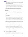
4-1 Troubleshooting Procedures ...........................................................................4-1
4-2 Technical Support Procedures ........................................................................4-4
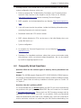
4-3 Frequently Asked Questions ...........................................................................4-5
4-4 Returning Merchandise for Service.................................................................4-6
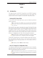
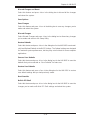
Chapter 5 BIOS
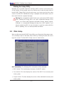
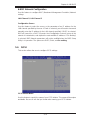
5-1 Introduction ......................................................................................................5-1
5-2 Main Setup ...................................................................................................... 5-2
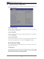
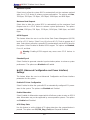
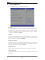
5-3 Advanced Setup Confi guration ....................................................................... 5-4
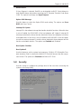
5-4 Chipset .......................................................................................................... 5-18
5-5 Server Management ...................................................................................... 5-25
5-6 iSCSI .............................................................................................................5-27
5-7 Boot Confi guration ........................................................................................5-28
5-8 Security .........................................................................................................5-29
5-9 Save & Exit ...................................................................................................5-30
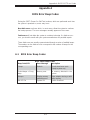
Appendix A BIOS Error Beep Codes
A-1 BIOS Error Beep Codes .................................................................................A-1
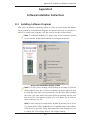
Appendix B Software Installation Instructions
B-1 Installing Software Programs ..........................................................................B-1
B-2 Confi guring Supero Doctor III .........................................................................B-2

1-1
Chapter 1: Quick Installation Guide
Chapter 1
Quick Installation Guide
If purchased a bare-bone system from Supermicro, the X8OBN-F Baseboard, the
X8OBN-CPU board, and the X8OBN-BRI Bridge card are enclosed in the chassis.
To prepare your system for proper installation, follow the instructions below.
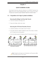
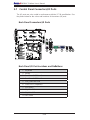
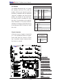
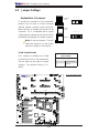
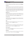
1-1 Preparation for Proper System Installation
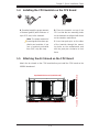
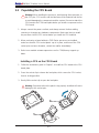
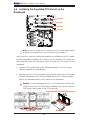
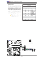
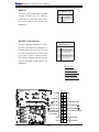
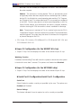
Removing the Bridge Card from the Chassis
Loosen the screws from the Bridge card.1.
Remove the Bridge card from the chassis.2.
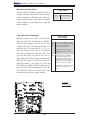
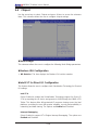
Removing the CPU Board from the Chassis
Locate the red latches on the handles of the CPU board.1.
Press both red latches outwards (towards the ends of the chassis) to release 2.
the CPU board from its locking position.
Push both handles upwards and gently pull the CPU board from the chassis.3.
A
B
Press the red latches outwards to
unlock the CPU Board
Pull the handles upwards to remove
the CPU Board from the chassis.
Note: All graphics and images are for illustration only. They may be differ-
ent from what you have in your system.

1-2
X8OBN-F Platform User's Manual
Standard
Standoff
Standard
Standoff
Locating Standoffs
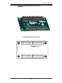
X8OBN Bridge card attached to the plate
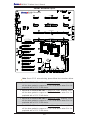
X8OBN-CPU
Rev.1.01
J43
J44
J45J46
J48J47
J35
J36
P2-DIMM6A
P2-DIMM5A
P2-DIMM7A
P2-DIMM8A
P2-DIMM2A
P2-DIMM1A
P2-DIMM3A
P2-DIMM4A
P1-DIMM6A
P1-DIMM5A
P1-DIMM7A
P1-DIMM8A
P1-DIMM4A
P1-DIMM3A
P1-DIMM2A
P1-DIMM1A
CPU1
CPU2
MB1
(for CPU2)
MB2
(for CPU2)
MB3
(for CPU2)
MB4
(for CPU2)
MB1
(for CPU1)
MB2
(for CPU1)
MB3
(for CPU1)
MB4
(for CPU1)
Locating Standoff
Locating Standoff
X8OBN CPU card
attached to the plate
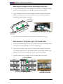
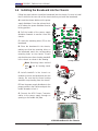
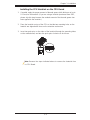
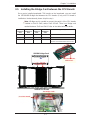
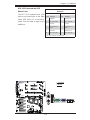
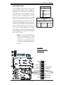
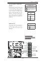
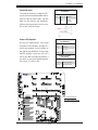
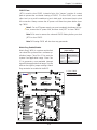
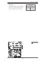
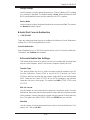
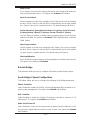
Attaching the Bridge Card to the Bridge Card Plate
Locate six mounting holes on the Bridge card. Locate four standard standoffs 1.
and two locating standoffs on the Bridge card plate as shown below.
Place the Bridge card on top of the Bridge card plate, making sure that the 2.
Bridge card properly rests on all standoffs with the two locating standoffs
protruding from the Bridge card plate.
Securely attach the Bridge card to the Bridge card plate with screws.3.
Attaching the CPU Board to the CPU Board Plate
Locate nine mounting holes on the CPU board. Locate seven standard stand-1.
offs and two locating standoffs on the CPU board plate.
Place the CPU board on top of the CPU board plate, making sure that the 2.
CPU board properly rests on all standoffs with the two locating standoffs pro-
truding from the CPU board plate as shown in the drawing below.
Securely attach the CPU board to the CPU board plate with screws.3.

1-3
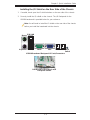
Chapter 1: Quick Installation Guide
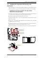
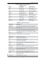
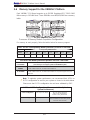
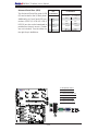
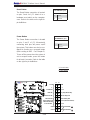
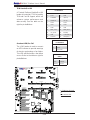
Keyboard
Mouse
USB 0/1
IPMI LAN
COM1 VGA
LAN1 LAN 2 UID
Switch
X8OBN Baseboard Backpanel IO Ports/Connectors
BaseBoard in the Chassis w/IO
Backplane Shown
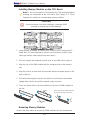
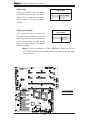
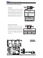
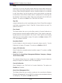
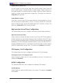
Installing the I/O Shield on the Rear Side of the Chassis
If needed, break open the IO shield windows on the rear side of the chassis.1.
Securely install the I/O shield on the chassis. The I/O Backpanel for the 2.
X8OBN baseboard is provided below for your reference.
Note: You will need to install the IO shield on the rear side of the chassis
before you install the baseboard into the chassis.

1-4
X8OBN-F Platform User's Manual
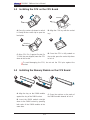
To avoid damaging the CPU, do not rub the CPU pins against the
socket.
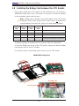
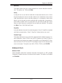
1-2 Installing the CPU on the CPU Board
A B
C
D
A. Press the socket clip down to unlock
it. Gently lift the socket clip to open the
load plate.
B. Align the CPU key with the socket
key.
D. Once the CPU is fully seated on
the socket, press the socket clip down
to lock it.
C. Align CPU Pin 1 against Socket Pin
1. Once they are aligned, lower the CPU
down to the socket.
1
2
CPU Key
CPU Pin 1
A B C
A. Align the key on the DIMM module
against the key of the DIMM socket.
B. Insert the DIMM module straight
down to the DIMM socket by pressing
both ends of the DIMM module at the
same time.
C. Press the notches on the ends of
the DIMM module inwards to lock it.
1-3 Installing the Memory Module on the CPU Board

1-5
Chapter 1: Quick Installation Guide
A B
A. If needed, apply the proper amount
of thermal grease (with thickness of
up to 0.13 mm) to the heatsink.
Note: The proper amount of
thermal grease has been ap-
plied to our heatsinks. If you
use a heatsink purchased
from SMC, skip this step.
B. Place the heatsink on top of the
CPU so that the two mounting holes
on the heatsink are aligned with those
on the retention mechanism.
C. Insert two push-pins on the sides
of the heatsink through the mount-
ing holes on the motherboard, and
turn the push-pins clockwise to lock
them.
1-4 Installing the CPU Heatsink on the CPU Board
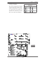
1-5 Attaching the Air Shroud on the CPU Board
Attach the air shroud on the CPU board before you install the CPU board on the
X8OBN baseboard.
Populated CPU Board (w/Air Shroud)
Populated CPU Board (w/Air Shroud) (Side View)
Populated CPU Board (w/Air Shroud) (Side View)

1-6
X8OBN-F Platform User's Manual
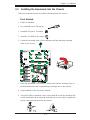
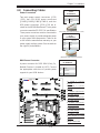
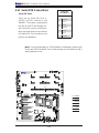
CPU Board Slot 4
Rev. 1.01
X8OBN-F Baseboard
KB/Mouse
IPMI LAN
USB 0/1
LED6
JPT1
JPL1
J25
J32
Fan12
Fan 11
LAN2
LAN1
UID
COM1
VGA
LAN CTRL
J29
J30
JUID_OW1
Fan 10
Fan 9
LED4
JPG1
BMC CTRL
JPB1
JPRST1
Slot1 PCI-E 2.0 x8 in x16
Slot2 PCI-E 2.0 x8 in x16
Slot3 PCI-E 2.0 x8
Slot4 PCI-E 2.0 x16
Slot5 PCI-E 2.0 x8
Slot6 PCI-E 2.0 x16
Slot7 PCI-E 2.0 x8
Slot8 PCI-E 2.0 x16
Slot9 PCI-E 2.0 x8
Slot10 PCI-E 2.0 x16
LED12
LED13
LED14
LED15
LED16
LED17
LED18
LED19
JTPM1
JBT1
JPME1
Fan1
JL1
I-SATA4
I-SATA3
I-SATA2
I-SATA0
USB4/5
USB2/3
USB10
USB8
JIPMB1
COM2
JWF1
JP3
JPWR3
BT1
J26
JD1
T-SGPIO2
T-SGPIO1
I-SATA5
Buzzer
JPWR4
JPWR1
JPWR2
PLX
PCI Bridge
I/O Hub 2
I/O Hub 1
ICH10R
Battery
PWR 1
PWR 2
Fan2
Fan7
Fan3
Fan4
Fan5
Fan6
JF1
FP CRTL
Fan8
CPU Board Slot 1
CPU Board Slot 2
JOH1
JWD1
JPME2
CPU Board Slot 3
JP16
JP17
JP19
JP18
I-SATA1
JP22
JP21
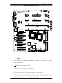
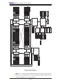
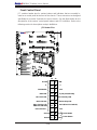
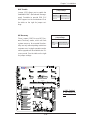
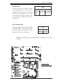
1-6 Installing the Baseboard into the Chassis
Follow the steps below to install the baseboard into the chassis. Be sure to install
the IO shield on the rear side of the chassis before you install the baseboard.
LS
E
D
C
A. Locate the release latches on the power
supply distributor. Press the release latch-
es to release the power distributor from its
locking position.
B. Pull the handle of the power supply
distributor forwards to remove it from the
chassis.
C. Locate the mounting holes (23) on the
baseboard.
D. Place the baseboard in the chassis,
making sure that the mounting holes on
the baseboard match the corresponding
mounting holes on the chassis. Please
note that there are three locating standoffs
in the chassis as shown in the drawing.
Note: Mounting Holes marked
with are for locating stand-
offs.
E. Install standoffs in the chassis as
needed to secure the baseboard onto the
chassis. Be sure that the three locating
standoffs are protruding from the chassis.
F. Place the power supply distributor to the
proper position in the chassis and push the
handle forwards to lock it.
G. Connect the HDD Power Connector
cables to the power supply through an
opening on the middle fan plate.
X8OBN BaseBoard in the Chassis
Locating Standoff
LS
LS
LS

1-7
Chapter 1: Quick Installation Guide
1-7 Installing the Populated CPU Board on the
Baseboard
After populating the CPU board with needed components, and installing the base-
board in the chassis, you can install the populate CPU board on the baseboard.
B
D
Installing the CPU Board (w/the CPU Board Plate
Attached) on the Baseboard
A. Locate the CPU board slots on the X8OBN baseboard. Insert a CPU board into
a CPU board slot by following the steps below, starting from Slot1.
B. Using two hands, hold the handles of the CPU board.
C. Align the guiding edges on the CPU handles against the guiding rails on both
sides of the chassis.
D. Insert the CPU board into the baseboard until the bottom of the CPU board
contacts the top of the CPU slot.
E. Using both handles on the CPU board, gently press the CPU board into the CPU
board slot until the CPU board is fully seated on the CPU slot.
F. Press the red latches on the handles to lock the CPU board to the baseboard.
Rev. 1.01
X8OBN-F Baseboard
X8OBN Baseboard
Populated CPU Board (w/Air Shroud)
CPU Board Slot1
CPU Board Slot2
CPU Board Slot3
CPU Board Slot4
A
CPU Board
BaseBoard
CPU Board Slot

1-8
X8OBN-F Platform User's Manual
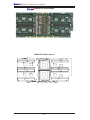
X8OBN-BR1 Bridge Card
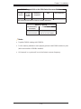
1-8 Installing the Bridge Card between the CPU Boards
Once you've installed the CPU boards on the baseboard, you can install the
X8OBN-BRI Bridge card on the CPU boards. (If only one CPU board is installed
on the baseboard, please skip this step.)
Note: A Bridge card is needed to connect the pair(s) of the CPU boards
installed on Slot1 & Slot2, and/or Slot3 & Slot4. There is no Bridge card
needed between Slot2 and Slot3. Refer to the table below for details.
CPU Board
Installed on
Slot1
CPU Board
Installed on
Slot2
CPU Board
Installed on
Slot3
CPU Board
Installed on
Slot4
X8OBN-BRI Bridge Card to be Installed
Yes No No No Not Needed
Yes Yes No No One card needed between Slot1 & Slot2
Yes Yes Yes No One card needed between Slot1 & Slot2
Yes Yes Yes Yes One card needed between Slot1 & Slot2;
Another card needed between Slot3 & Slot4
To install the Bridge card between the CPU boards, follow the steps below:
A. Place the Bridge card on top of the CPU boards, making sure that the Bridge
card properly rests on both CPU boards.
B. Insert four screws on the Bridge card to secure it on the CPU boards.
Populated CPU Board with Air Shroud
To Connect to the CPU Board
Bridge Card
Two Bridge Cards
Four CPU Boards

1-9
Chapter 1: Quick Installation Guide
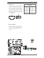
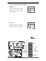
1-9 Installing Internal Peripherals
1-10 Installing External Peripherals
Add-on Cards SATA Drives
A
B
Keyboard
Mouse
USB 0/1
IPMI LAN
COM1 VGA
LAN1 LAN 2
UID
Switch
Notes:
All graphics and images are for illustration only. They may be different from 1.
what you have in your system.
For more details on power cable connection, please refer to Section 3-8 in 2.
Chapter. Also refer to Chapter 3 for more information on system installation.

1-10
X8OBN-F Platform User's Manual
Notes

Chapter 2: Overview
2-1
Chapter 2
Overview
2-1 Overview
Checklist
Congratulations on purchasing your computer system from an acknowledged leader
in the industry. Supermicro systems are designed with the utmost attention to detail
to provide you with the highest standards in quality and performance.
For more information regarding this product, please visit our website at www.
supermicro.com.

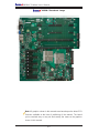
2-2
X8OBN-F Platform User’s Manual
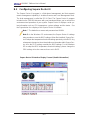
X8OBN-F Baseboard Image
Note: All graphics shown in this manual were based upon the latest PCB
Revision available at the time of publishing of the manual. The board
you've received may or may not look exactly the same as the graphics
shown in this manual.
Page is loading ...
Page is loading ...
Page is loading ...
Page is loading ...
Page is loading ...
Page is loading ...
Page is loading ...
Page is loading ...
Page is loading ...
Page is loading ...
Page is loading ...
Page is loading ...
Page is loading ...
Page is loading ...
Page is loading ...
Page is loading ...
Page is loading ...
Page is loading ...
Page is loading ...
Page is loading ...
Page is loading ...
Page is loading ...
Page is loading ...
Page is loading ...
Page is loading ...
Page is loading ...
Page is loading ...
Page is loading ...
Page is loading ...
Page is loading ...
Page is loading ...
Page is loading ...
Page is loading ...
Page is loading ...
Page is loading ...
Page is loading ...
Page is loading ...
Page is loading ...
Page is loading ...
Page is loading ...
Page is loading ...
Page is loading ...
Page is loading ...
Page is loading ...
Page is loading ...
Page is loading ...
Page is loading ...
Page is loading ...
Page is loading ...
Page is loading ...
Page is loading ...
Page is loading ...
Page is loading ...
Page is loading ...
Page is loading ...
Page is loading ...
Page is loading ...
Page is loading ...
Page is loading ...
Page is loading ...
Page is loading ...
Page is loading ...
Page is loading ...
Page is loading ...
Page is loading ...
Page is loading ...
Page is loading ...
Page is loading ...
Page is loading ...
Page is loading ...
Page is loading ...
Page is loading ...
Page is loading ...
Page is loading ...
Page is loading ...
Page is loading ...
Page is loading ...
Page is loading ...
Page is loading ...
Page is loading ...
Page is loading ...
Page is loading ...
Page is loading ...
Page is loading ...
Page is loading ...
Page is loading ...
Page is loading ...
Page is loading ...
Page is loading ...
Page is loading ...
Page is loading ...
Page is loading ...
Page is loading ...
-
 1
1
-
 2
2
-
 3
3
-
 4
4
-
 5
5
-
 6
6
-
 7
7
-
 8
8
-
 9
9
-
 10
10
-
 11
11
-
 12
12
-
 13
13
-
 14
14
-
 15
15
-
 16
16
-
 17
17
-
 18
18
-
 19
19
-
 20
20
-
 21
21
-
 22
22
-
 23
23
-
 24
24
-
 25
25
-
 26
26
-
 27
27
-
 28
28
-
 29
29
-
 30
30
-
 31
31
-
 32
32
-
 33
33
-
 34
34
-
 35
35
-
 36
36
-
 37
37
-
 38
38
-
 39
39
-
 40
40
-
 41
41
-
 42
42
-
 43
43
-
 44
44
-
 45
45
-
 46
46
-
 47
47
-
 48
48
-
 49
49
-
 50
50
-
 51
51
-
 52
52
-
 53
53
-
 54
54
-
 55
55
-
 56
56
-
 57
57
-
 58
58
-
 59
59
-
 60
60
-
 61
61
-
 62
62
-
 63
63
-
 64
64
-
 65
65
-
 66
66
-
 67
67
-
 68
68
-
 69
69
-
 70
70
-
 71
71
-
 72
72
-
 73
73
-
 74
74
-
 75
75
-
 76
76
-
 77
77
-
 78
78
-
 79
79
-
 80
80
-
 81
81
-
 82
82
-
 83
83
-
 84
84
-
 85
85
-
 86
86
-
 87
87
-
 88
88
-
 89
89
-
 90
90
-
 91
91
-
 92
92
-
 93
93
-
 94
94
-
 95
95
-
 96
96
-
 97
97
-
 98
98
-
 99
99
-
 100
100
-
 101
101
-
 102
102
-
 103
103
-
 104
104
-
 105
105
-
 106
106
-
 107
107
-
 108
108
-
 109
109
-
 110
110
-
 111
111
-
 112
112
-
 113
113


Supermicro X8OBN-F User manual
- Category
- Server/workstation motherboards
- Type
- User manual
Ask a question and I''ll find the answer in the document
Finding information in a document is now easier with AI
Related papers
-
Supermicro X8OBN-CPU User manual
-
-
-
-
-
-
-
-
-
Supermicro Super X8DTL-iF User manual
Other documents
-
A-Link HUBU4 Datasheet
-
Gamdias AEOLUS M2-1204R User manual
-
Zebra NX-7510/NX-7520/NX-7530 Owner's manual
-
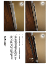 Baseboarders BC001-36 Installation guide
-
Gigabyte GA-7TCSV2 User manual
-
MSI 5520 Master Series User manual
-
Gamdias AEOLUS M1-1205R User manual
-
-
-
