
Installation, Operation
and Maintenance Manual
Handwheel Operated Valves (903, 913, 963)
Designed and Manufactured by ITT
IOM.HWO.ASCO.en-US.2017-11


Table of Contents
Handwheel Operated Valves (903, 913, 963) Installation, Operation, and Maintenance Manual 1
Table of Contents
Introduction and Safety .......................................................................................................... 2
Safety message levels ............................................................................................................ 2
User health and safety ............................................................................................................ 2
Transportation and storage .................................................................................................... 4
Handling and unpacking guidelines ........................................................................................ 4
Storage, disposal, and return requirements ............................................................................ 4
Product Description ................................................................................................................ 5
Topworks identification ........................................................................................................... 5
Bonnet description .................................................................................................................. 5
Valve diaphragm identification ................................................................................................ 5
Installation ............................................................................................................................... 7
Install the valve and topworks ................................................................................................. 7
Tighten the bonnet fasteners .................................................................................................. 7
Fastener torque table for valve body to topworks ................................................................. 8
the travel stop ......................................................................................................................... 9
Operation ............................................................................................................................... 10
Topworks operation .............................................................................................................. 10
Operate the Adjustable Open Stop ....................................................................................... 10
Maintenance ........................................................................................................................... 12
Precautions ........................................................................................................................... 12
Inspection ............................................................................................................................. 12
Lubrication requirements ...................................................................................................... 12
Disassemble the valve .......................................................................................................... 12
Replace the valve diaphragm ................................................................................................ 13
Change the diaphragm type .................................................................................................. 14
Replace the o-rings ............................................................................................................... 15
Parts Listing and Cross-Sectional Drawings ...................................................................... 17
963 PAS plastic bonnet ......................................................................................................... 17
Designed and Manufactured by ITT

Introduction and Safety
Handwheel Operated Valves (903, 913, 963) Installation, Operation, and Maintenance Manual2
Introduction and Safety
Safety message levels
Definitions
Safety message level Indication
DANGER:
A hazardous situation which, if not avoided, will
result in death or serious injury
WARNING:
A hazardous situation which, if not avoided,
could result in death or serious injury
CAUTION:
A hazardous situation which, if not avoided,
could result in minor or moderate injury
Electrical Hazard:
The possibility of electrical risks if instructions
are not followed in a proper manner
NOTICE:
• A potential situation which, if not avoided,
could result in an undesirable result or
state
• A practice not related to personal injury
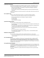
User health and safety
General precautions
This product is designed and manufactured using good workmanship and materials, and meets
all applicable industry standards. This product should be used only as recommended by ITT or
ASCO.
WARNING:
• Misapplication of the valve can result in injury or property damage. Select valves and valve
components of the proper materials and make sure that they are consistent with your
specific performance requirements. Incorrect application of this product includes but is not
limited to:
• Exceeding the pressure or temperature rating
• Failing to maintain this product according to the recommendations
• Using this product to contain or control media that is incompatible with the materials of
construction
• Proper containment or protection from hazardous media must be provided by the end
user to protect employees and the environment from valve discharge.
• If the product exhibits any indication of leakage, do not operate. Isolate the product and
either repair it or replace it as outlined within this manual.
Designed and Manufactured by ITT

Introduction and Safety
Handwheel Operated Valves (903, 913, 963) Installation, Operation, and Maintenance Manual 3
Qualifications and training
The personnel responsible for the assembly, operation, inspection, and maintenance of the
valve must be appropriately qualified. The operating company must do the following tasks:
• Define the responsibilities and competency of all personnel handling this equipment.
• Provide instruction and training.
• Ensure that the contents of the operating instructions have been fully understood by the
personnel.
Instruction and training can be carried out by ASCO as the reseller of the valve by order of the
manufacturer.
Non-compliance risks
Failure to comply with all safety precautions can result in the following conditions:
• Death or serious injury due to electrical, mechanical, and chemical influences
• Environmental damage due to the leakage of dangerous materials
• Product damage
• Property damage
• Loss of all claims for damages
Operational safety precautions
Be aware of these safety precautions when operating this product:
• Do not leave hot or cold components of the product unsecured against contact if they are a
source of danger.
• Do not remove the contact guard for moving parts when the product is in operation. Never
operate the product without the contact guard installed.
• Do not hang items from the product. Any accessories must be firmly or permanently
attached.
• Do not use the product as a step or hand hold.
• Do not paint over the identification tag, warnings, notices, or other identification marks
associated with the product.
Maintenance safety precautions
Be aware of these safety precautions when performing maintenance on this product:
• You must decontaminate the product if it has been exposed to harmful substances such as
caustic chemicals.
Use of unauthorized parts
Reconstruction or modification of the product is only permissible after consultation with ITT.
Genuine spare parts and accessories authorized by ITT serve to maintain safety. Use of non-
genuine ITT parts can annul liability of the manufacturer for the consequences. ITT parts are
not to be used in conjunction with products not supplied by ITT as this improper use can annul
all liability for the consequences.
Unacceptable modes of operation
The operational reliability of this product is only guaranteed when it is used as designated. The
operating limits given on the identification tag and in the data sheet may not be exceeded under
any circumstances. If the identification tag is missing or worn, contact ASCO for specific
instructions.
Do not use "cheater bars" to operate manual valves. Damage to the valve or personal injury
could result.
Designed and Manufactured by ITT

Transportation and storage
Handwheel Operated Valves (903, 913, 963) Installation, Operation, and Maintenance Manual4
Transportation and storage
Handling and unpacking guidelines
CAUTION:
Always observe the applicable standards and regulations regarding the prevention of
accidents when handling the product.
Handling guidelines
Follow these guidelines when handling the product to prevent damage:
• Use care when handling the product.
• Leave protective caps and covers on the product until installation.
Unpacking guidelines
Follow these guidelines when unpacking the product:
1. Inspect the package for damaged or missing items upon delivery.
2. Note any damaged or missing items on the receipt and freight bill.
3. Do not lift or pull on the electrical conduit lines. Doing so may cause the POC switches to
come out of calibration.
Storage, disposal, and return requirements
Storage
If you are not immediately installing the product after delivery, store it as follows:
• Store the product in a dry room that maintains a constant temperature.
• Make sure that the products are not stacked on top of one another.
Disposal
Dispose of this product and associated components in compliance with federal, state, and local
regulations.
Return
Ensure these requirements are met before you return a product to ASCO:
• Contact ASCO for specific instructions on how to return the product.
• Clean the valve of all hazardous material.
• Complete a Material Safety Data Sheet or Process Data Sheet for any process fluid that
could remain on the valve.
• Obtain a Return Material Authorization from the factory.
Designed and Manufactured by ITT

Product Description
Handwheel Operated Valves (903, 913, 963) Installation, Operation, and Maintenance Manual 5
Product Description
Topworks identification
Model number
Code Description
903 Cast iron bonnet with rising stem and travel stop
903S Cast iron sealed bonnet with rising stem and travel stop
913 Stainless steel bonnet with rising stem and travel stop
913S Stainless steel sealed bonnet with rising stem and travel stop
963 PAS plastic bonnet with rising handwheel and travel stop
963S PAS plastic sealed bonnet with rising handwheel and travel stop
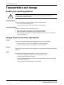
Bonnet description
Non-Sealed bonnet
The non-sealed bonnet has a weep hole that indicates a diaphragm failure by allowing process
fluid that accumulates in the bonnet to pass through the hole.
Sealed bonnet
The sealed bonnet uses a special “V-notch” vent plug, which permits leak detection.
Figure 1: Weep hole and V-notch vent plug
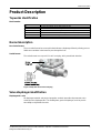
Valve diaphragm identification
Diaphragm tab codes
All diaphragm materials and physical properties are batch traceable via permanent codes
molded into the diaphragm tabs. The molding date, grade of diaphragm, and size provide
traceability to original batch records.
Designed and Manufactured by ITT

Product Description
Handwheel Operated Valves (903, 913, 963) Installation, Operation, and Maintenance Manual6
1. Date code
2. Supplier code
Figure 2: Elastomer diaphragm front
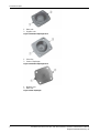
1. Valve size
2. Grade of diaphragm
Figure 3: Elastomer diaphragm back
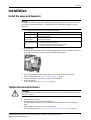
1. Material code
2. Date code
Figure 4: PTFE diaphragm
Designed and Manufactured by ITT

Installation
Handwheel Operated Valves (903, 913, 963) Installation, Operation, and Maintenance Manual 7
Installation
Install the valve and topworks
NOTICE:
The topworks size and configuration can limit the actual operating pressure. Consult the Pure-
Flo catalog for pressure limitations. Consult the factory or engineering catalog for vacuum
operation.
1. If you have a weld end valve, then consider the following:
If you are welding ... Then ...
Manually Remove the topworks.
Remove the diaphragm.
In line for schedule 10
or heavier pipe
Remove the topworks.
Remove the diaphragm.
In line for schedule 5
or lighter pipe and tub-
ing
You can weld with automatic equipment. Before you perform the weld:
1. Remove the topworks (optional).
2. If left installed, set the valve to the open position.
3. Properly purge the valve with an inert gas.
2. Install the valve.
Install with the raised hash marks (castings) or small machined dots (forgings) on the valve
body at the 12 o'clock position to achieve the optimum drain angle.
3. Prior to pressurization (with the valve slightly open), tighten the bonnet fasteners.
For more information, see Tighten the bonnet fasteners (page 7).
4. Cycle the valve two to three times to verify smooth operation.
5. Set the travel stop.
For more information, see the travel stop (page 9).
Tighten the bonnet fasteners
CAUTION:
Do not tighten fasteners while the system is pressurized or at elevated temperatures (greater
than 38°C | 100°F).
1. Depressurize the system.
2. Position diaphragm so that valve is slightly open.
For valves with an actuator, you may need to use regulated air pressure to actuate the
valve.
3. Tighten the bonnet fasteners in a crisscross pattern.
For more information, see Fastener torque table for valve body to topworks (page 8).
Designed and Manufactured by ITT

Installation
Handwheel Operated Valves (903, 913, 963) Installation, Operation, and Maintenance Manual8
4. Make multiple crisscross passes to build up torque to the final table value. Make additional
crisscross passes using final table values to evenly tighten each fastener to within 5% of
torque value.
5. Retighten the bonnet fasteners as noted above at ambient conditions after the system has
cycled through operating pressure and temperature.
6. Monitor the valve for leakage:
If leakage ... Then ...
Occurs at the body/bonnet flange
sealing area
Depressurize the system and retighten the bonnet fasteners as
noted above.
Continues Depressurize the system and retighten the bonnet fasteners as
noted above. (maximum 3rd re-torque)
Continues Replace the valve diaphragm.
For more information, see Replace the valve diaphragm (page 13).
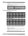
Fastener torque table for valve body to topworks
Table 1: PAS bonnet (963)
Values given are for lubricated fasteners.
Valve size, inches (DN) PTFE diaphragm Elastomer diaphragm
Inches DN in-lb N-m in-lb N-m
0.50 15 20-50 2.3-5.7 20-40 2.3-4.5
0.75 20 40-70 4.5-7.9 20-50 2.3-5.7
1.00 25 45-80 5.1-9.1 25-70 2.8-7.9
1.50 40 145-170 16-19 75-130 8.5-14.7
2.00 50 225-275 25-31 100-180 11-20
2.50 65 500-830 57-94 300-420 34-48
3.00 80 500-830 57-94 300-420 34-48
4.00 100 200-575 23-65 180-220 20-25
Table 2: Metal bonnet (903, 913)
Values given are for lubricated fasteners.
Valve size PTFE diaphragm Elastomer diaphragm
Inch DN in-lb N-m in-lb N-m
0.50 15 25-80 2.8-9.1 20-40 2.3-4.5
0.75 20 50-80 5.7-9.1 20-50 2.3-5.7
1.00 25 65-120 7.4-13.6 45-70 5.1-7.9
1.25 and 1.50 32 and 40 200-225 23-25 75-130 8.5-14.7
2.00 50 225-300 25-34 100-180 11-20
2.50 65 750-1000 85-113 300-420 34-48
3.00 80 750-1000 85-113 300-420 34-48
4.00 100 540-600 61-68 190-230 22-26
NOTICE:
1. Make multiple criss-cross passes to build up torque to final table values. Make additional
criss-cross passes using table vales to evenly tighten each bolt to within 5% of stated
torque.
2. Values given are for lubricated fasteners.
3. Minimum values given will provide longer diaphragm cycle life for valves in non-autoclave
and low thermal cycle conditions.
4. Maximum values given will be required for autoclave conditions and for high thermal cycle
conditions.
5. Torques should be applied at or near ambient conditions <38°C |100°F.
Designed and Manufactured by ITT

Installation
Handwheel Operated Valves (903, 913, 963) Installation, Operation, and Maintenance Manual 9
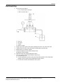
the travel stop
1. Do you have a test fixture?
• If Yes: Follow steps 2 through 6.
• If No: Proceed to step 7.
1. Stop nut
2. Air supply
3. Tubing
4. Beaker of water
2. Supply air pressure equal to the system operating pressure to one side of the valve.
3. Cap the other side of the valve and install a venting rubber or plastic tube.
4. Hold the tube in a container of water.
5. Turn the handwheel closed until the leakage stops.
Air bubbles indicate leakage.
6. Adjust the travel stop nut tight against the spacer.
7. If you do not have a fixture, then follow the steps below:
a) Loosen the lock nut.
b) Turn the handwheel clockwise until you feel the initial resistance of the diaphragm
seating. From this point, turn the handwheel another 5/8 turn.
c) Turn the lock nut down until it bottoms on the spacer.
Designed and Manufactured by ITT

Operation
Handwheel Operated Valves (903, 913, 963) Installation, Operation, and Maintenance Manual10
Operation
Topworks operation
WARNING:
For a sealed bonnet, the bonnet intervals and seals should be constructed of materials suitable
for exposure to the process fluid or gas. If in doubt, contact ITT for evaluation.
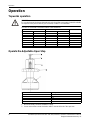
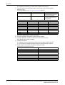
The valve is closed with a clockwise rotation of the handwheel.
Valve size Stem travel Number of turns
Inch DN Inch mm
0.50 15 0.25 6.4 2
0.75 20 0.38 9.5 3
1.00 25 0.50 13 4
1.25 and 1.50 32 and 40 0.81 21 4.88
2.00 50 1.12 29 6.75
2.50 65 1.61 41 8.12
3.00 80 1.61 41 8.12
4.00 100 2.12 54 10.62
Operate the Adjustable Open Stop
Item Description
1 Bonnet assembly
2 Handwheel
3 Cap
4 Nut
5 Capscrew
1. Bonnet assembly should be installed to a body.
2. Loosen nut and turn counter clockwise until it is next to the head of the capscrew.
Designed and Manufactured by ITT

Operation
Handwheel Operated Valves (903, 913, 963) Installation, Operation, and Maintenance Manual 11
3. Back out capscrew turn counter clockwise until the lower end is flush with the underside of
cap.
4. Turn handwheel until it is in the desired open position.
5. Turn capscrew clockwise until its lower end is in contact with the top of the stem of the
bonnet assembly.
6. Turn the nut clockwise tight against the top of the cap.
Opening stop is now set.
Designed and Manufactured by ITT

Maintenance
Handwheel Operated Valves (903, 913, 963) Installation, Operation, and Maintenance Manual12
Maintenance
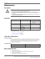
Precautions
WARNING:
• All procedures must be performed by qualified personnel.
• When the process fluid is hazardous, thermal (hot or cold), or corrosive, take extra
precautions. Employ the appropriate safety devices and be prepared to control a process
media leak.
• Always wear protective clothing and equipment to safeguard the eyes, face, hands, skin,
and lungs from the fluid in the line.
Inspection
Inspection area What to look for Action if problem is found
External valve parts Excessive wear or corrosion
• Replace the affected parts
• Contact ITT to obtain re-
placement parts or for specif-
ic instructions
Non sealed bonnet Fluid weeping from the weep hole Replace the valve diaphragm
Sealed bonnet Fluid weeping from the plug
Loosen the v-notch vent plug 2-3
turns to check
Replace the valve diaphragm
Topworks Spindle binding, excessive noise,
or dried lubricant
Lubricate the topworks
Diaphragm and valve body Leakage between the diaphragm
and valve body
Tighten the bonnet fasteners
For more information, see:
• Replace the valve diaphragm (page 13)
• Lubrication requirements (page 12)
• Tighten the bonnet fasteners (page 7)
Lubrication requirements
Lubrication schedule
Remove residual grease prior to re-lubrication. Lubricate the spindle threads, thrust bearing,
lower spindle face and neck where it interfaces with the compressor, and o-ring whenever the
topworks is disassembled. Bonnets are not equipped with grease fittings and must be
disassembled to be lubricated.
Acceptable lubricants
Brand Lubricant type
Chevron FM ALC EP 2 (FDA Compliant)
Fuchs Cassida FM CSC EP2 (FDA Compliant)
Disassemble the valve
1. Remove all line pressure.
2. Turn the valve to the open position counter clockwise at least one turn.
3. Remove the bonnet fasteners.
4. Lift the topworks assembly from the valve body.
Designed and Manufactured by ITT

Maintenance
Handwheel Operated Valves (903, 913, 963) Installation, Operation, and Maintenance Manual 13
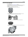
Replace the valve diaphragm
1. Disassemble the valve.
For more information, see Disassemble the valve (page 12).
2. Unscrew the diaphragm from the compressor by turning the diaphragm counterclockwise.
The replacement diaphragm should be identical in size and grade to the original
diaphragm.
3. If replacing a PTFE diaphragm, then follow these steps.
a) Install the new elastomer backing cushion over the tube nut.
b) Invert the PTFE diaphragm by pressing the center of the diaphragm face with your
thumbs while holding the edge of the diaphragm with your fingers.
c) Engage the threads of the diaphragm into the tube nut by rotating clockwise.
d) Continue rotating the PTFE diaphragm clockwise into the compressor while securing
the backing cushion from rotating.
Designed and Manufactured by ITT

Maintenance
Handwheel Operated Valves (903, 913, 963) Installation, Operation, and Maintenance Manual14
4. Rotate the diaphragm until hard stop or heavy resistance is achieved and additional force
does not significantly rotate the diaphragm into the compressor.
5. If replacing a PTFE diaphragm, re-invert the diaphragm.
6. Back off (no more than half turn) until the bolt holes in diaphragm and the bonnet flange
align.
7. Rotate the handwheel counterclockwise just enough to permit the flange area of the
diaphragm to rest flat against the flange area of the bonnet.
8. Replace the topworks assembly on the body and tighten the bonnet fasteners.
For more information, see Tighten the bonnet fasteners (page 7).
9. Set the travel stop.
For more information, see the travel stop (page 9).
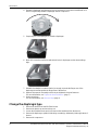
Change the diaphragm type
1. Remove the bonnet nuts and lift off the bonnet.
2. Remove the plastic cap and travel stop nut.
3. Loosen the handwheel setscrew(s) and remove the handwheel from the bonnet.
4. Remove the diaphragm, spindle and bushing assembly by withdrawing it through bottom of
bonnet.
5. Remove the compressor.
Designed and Manufactured by ITT

Maintenance
Handwheel Operated Valves (903, 913, 963) Installation, Operation, and Maintenance Manual 15
If the compressor to spindle connection is a ... Then ...
Spring pin Drive out the spring pin that retains the compres-
sor
"T" slot Slide the compressor off the spindle
6. Change to the new compressor.
If you are changing ... Then ...
From an elastomer to a PTFE diaphragm Install a tube nut into the hexagonal hole in the
new compressor
From a PTFE to an elastomer diaphragm Change to the new compressor.
7. Install the new compressor.
If the compressor to spindle connection is a ... Then ...
Spring pin Locate the new compressor on the spindle and
drive in the spring pin
“T” slot Slide the new compressor onto the spindle
Replace the o-rings
1. Disassemble the topworks:
a) Remove the bonnet nuts and lift off the bonnet.
b) Remove the plastic cap and travel stop nut.
c) Loosen the handwheel setscrews and remove the handwheel from the bonnet.
d) Remove the diaphragm, spindle, and bushing assembly by withdrawing it through the
bottom of the bonnet.
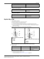
2. Remove o-ring 1 from the groove in the bushing outside diameter.
Figure 5: O-rings for 0.50–2.00 inch (DN
15–50) valve
1. O-ring 1
2. O-ring 2
3. O-ring 3
Figure 6: O-rings for 2.50–4.00 inch (DN 65–100)
valve
1. O-ring 1
2. O-ring 2
3. O-ring 3
4. O-ring 4
3. Unscrew the diaphragm and spindle assembly from the handwheel bushing.
4. Remove o-rings:
Valve size (in) Valve size (DN) Action
.5–2 15–50 Remove o-ring 2 from the groove
in spindle outside diameter.
2.5–6 80–150 Remove o-rings 2 and 4 from the
spindle plug.
5. Install the thrust bearing or washer:
a) Lubricate the thrust bearing or washer.
For more information, see Lubrication requirements (page 12).
Designed and Manufactured by ITT

Maintenance
Handwheel Operated Valves (903, 913, 963) Installation, Operation, and Maintenance Manual16
b) Install the thrust bearing or washer on the shoulder of the bushing.
6. Cover the stem threads with masking tape to protect the o-rings during installation.
7. Lubricate o-rings.
For more information, see Lubrication requirements (page 12).
Valve size (in) Valve size (DN) Action
.5–2 15–50 Lubricate o-rings 1 and 2 and
insert them into the grooves in
the bushing and spindle.
2.5–6 80–150 Lubricate o-rings 2 and 4 and
insert them into the grooves in
the spindle plug.
Select the proper o-rings for the valve size.
Valve size, inches (DN) O-ring 1 O-ring 2 O-ring 4
0.50 (15) .445 x .063 #107 –
0.75 (20) .571 x .063 #109 –
1.00 (25) .634 x .063 #110 –
1.25 (32) #119 #112 –
1.50 (40) #119 #112 –
2.00 (50) #119 #112 –
2.50 (65) #218 #209 #212
3.00 (80) #218 #209 #212
4.00 (100) #220 #210 #214
8. Remove the masking tape from the stem threads.
9. Screw the diaphragm and spindle assembly into the bushing.
10. Install the diaphragm, spindle, and bushing assembly into the bonnet.
Verify that the shim washer is installed.
11. Install the handwheel:
a) Tighten the setscrews, ensuring the setscrew ends engage the bushing holes.
b) If you do not have a plastic handwheel, then use a thread locking compound.
12. Install o-ring 3 and screw the cap onto the bushing hand tight.
Select the proper o-ring for the valve size.
Valve size, inches (DN) O-ring 3
0.50 (15) #118
0.75 (20) #119
1.00 (25) #121
1.25 (32) #122
1.50 (40) #122
2.00 (50) #122
2.50 (65) #128
3.00 (80) #128
4.00 (100) #130
Designed and Manufactured by ITT

Parts Listing and Cross-Sectional Drawings
Handwheel Operated Valves (903, 913, 963) Installation, Operation, and Maintenance Manual 17
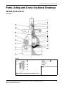
Parts Listing and Cross-Sectional Drawings
963 PAS plastic bonnet
List of parts
Figure 7:
Figure 8: Bonnet and bolting detail for fabrications with
studs
Figure 9: V-notch vent plug for sealed
bonnet
Designed and Manufactured by ITT

Parts Listing and Cross-Sectional Drawings
Handwheel Operated Valves (903, 913, 963) Installation, Operation, and Maintenance Manual18
1
For 3–4 in. (DN80–100) sanitary internals are optional.
2
Sanitary internals include a stainless steel spindle and bronze compressor.
3
For “T” slot connection between spindle and compressor, the spirol pin is not used.
4
ASME grade fasteners are available on tank botton valve.
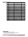
Item Description Material Quantity
1 Spindle Stainless steel (0.5–2 in (DN15–50)
Carbon steel (3–4 in (DN80–100)
1
1
2 Locknut Stainless steel 4
3 Washer Stainless steel 1
4 Wiper seal Viton
Polyolefin foam
1
5 O-ring Viton 1
6 Screw Stainless steel 1 or 2
7 O-ring Viton 1
8 O-ring Viton 1
9 Thrust bearing Polyethylene As required
10 Bushing Brass 1
11
2
Compressor Bronze or stainless steel 1
12
3
Spirol pin Silicone 1
13 Tube nut Brass 1
14 Backing cushion EPDM 1
15 Diaphragm PTFE 1
16 Metal body Stainless steel 1
17 Cap screw Stainless steel 4
18 Plain washer Stainless steel 4
19 Bonnet Polyarylsulfone 1
20 Hex nut Stainless steel 4
21 Nut cover cap Polyarylsulfone 4
22 Shim washer Polyethylene As required
23 Handwheel Polyarylsulfone 1
24 Cap Polyphenylsulfone 1
25 Stud Stainless steel 4
26 Spacer Stainless steel 4
27 Body Stainless steel 1
28
4
Hex nut Stainless steel 4
29 V-notch vent plug Stainless steel 1
Designed and Manufactured by ITT
Page is loading ...
Page is loading ...
-
 1
1
-
 2
2
-
 3
3
-
 4
4
-
 5
5
-
 6
6
-
 7
7
-
 8
8
-
 9
9
-
 10
10
-
 11
11
-
 12
12
-
 13
13
-
 14
14
-
 15
15
-
 16
16
-
 17
17
-
 18
18
-
 19
19
-
 20
20
-
 21
21
-
 22
22


Ask a question and I''ll find the answer in the document
Finding information in a document is now easier with AI
Related papers
Other documents
-
Kohler 1328515 Installation guide
-
Asco Series 224 Aseptic Valves Handwheel Operated (970) Installation guide
-
-
ITT Engineered Valves BioviZion Installation, Operation and Maintenance Manual
-
-
William Powell Co 0.75 GA08SA58GB Installation guide
-
 William Powell Co 2.0 2341SN0TXXX Installation guide
-
-
THE ORIGINAL GRANITE BRACKET KW-18-A User manual
-
 Dixon Gate Valve User manual

