Page is loading ...

YARWAY MODEL 5817 AND 5827 HY-DROP THROTTLING VALVES
InstallatIon, operatIon and maIntenance InstructIons
Before installation these instructions must be fully read and understood
© 2017 Emerson. All Rights Reserved.Emerson.com/FinalControl VCIOM-03125-EN 18/02
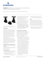
Designed for high pressure, high temperature
throttling service in modern steam power
plants, Hy-Drop valves are recommended for
continuous blow down, sampling, high pressure
vents, boiler feed pump by-pass relief, or any
high pressure drop service in which erosive and
wire drawing conditions are severe enough to
destroy conventional globe or venturi valves.
WARNING
Hot discharge from this product may cause severe
burns. Discharge must be piped away or directed
so that persons in the vicinity are not endangered.
This product must be isolated, vented and cool to
the touch before repairing or inspecting.
DESIGN FEATURES
• All working parts removable through yoke.
• Stellite disc, with separate surfaces for
shut-off and control; spring-loaded stem
connection; fully guided for perfect alignment,
precise control al vibration reduction.
• One piece body construction.
• Interchangeable disc-stem assemblies
available for quick conversion of nominal
orifice sizes without removing valve from line.
• Micrometer dial assures accurate set and
reset capability.
• Yarway reseating tools allow recutting of
worn or damaged seats without removing the
valve body from the line.
INSTALLATION
Yarway Hy-Drop valves are installed with flow
entering above the seat.
Standard material for forged Hy-Drop valves
is ASME SA 182 Grade F22 steel. Suggested
AWS-ASTM welding rod for F22 valve body
material is AWS-ASTM E9018 B3. Since welding
procedure is dependent upon various codes
established by customers, contractors, and/or
government rulings, qualification to the specific
code involved should be followed.
OPERATION
Hy-Drop Valves are designed for dual range
throttling through a primary range of six
complete handle revolutions, plus a super-
capacity blast range on the seventh and eighth
handle revolutions for purging foreign particles
from the line or for accelerated drainage of a
system during start-up or shut-down.
The first six turns provide linear throttling. The
seventh and eighth turns elevate the disc above
the primary throttling range to provide a “full-
porting” high capacity delivery. The Tee Handle
provides ample closing force, and additional
leverage is not recommended.

2
11
12
17
15
2
10
18
20
5
1
22
21
13
14
9
7
3
8
6
4
YARWAY MODEL 5817 AND 5827 HY-DROP THROTTLING VALVES
InstallatIon, operatIon and maIntenance InstructIons
CARE OF VALVE
Stem lubrication is not required due to the non-
galling properties of the bronze yoke bushing
and stainless steel stem.
Packing must be sufficiently compressed
to prevent stem leakage. Excessive packing
compression will shorten packing life and
may cause abnormal operating torque.
When packing adjustments are required,
compression should be no more than that
required to stop the leakage. When packing
can no longer be adjusted, it must be replaced.
When it is necessary to remove all packing
from the stuffing box proceed as outlined in
“Disassembly”.
DISASSEMBLY
All internal parts of the Hy-Drop valve can be
removed without disconnecting the body from
the line. Before attempting disassembly make
certain that all line pressure is relieved and the
pipeline is secured against pressurization.
When the inside of the valve must be cleaned,
or a foreing body lodged in the valve prevents
proper seating of the disc, or the disc-stem
assembly must be converted to another
nominal orifice size:
1. Loosen the indicator set screw and indicator
bushing set screws.
2. Remove the gland bolts and split gland
bushing.
3. Turn the tee handle counter-clockwise past
the fully open position to force the packing
and stuffing box bushing out of the stuffing
box.
4. Remove the tack weld on the yoke bushing
and unscrew this bushing to remove all
internal parts through the top of the yoke.
5. Disassemble the tee handle, yoke bushing,
indicator bushing, packing and stuffing box
bushing.
PARTS
Item Description
1 Body
2 Gland
3 Indicator and Set Screws
4 Stem
5 Stuffing Box Bushing
6 Packing
7 Indicator Bushing & Set Screws
8 Split Gland Bushing
9 Yoke Bushing
10 Yoke
11 Tee Handle
12 Washer
13 Hex Nut, Stem
14 Washer
15 Indicator Scale & Nameplate
17 Hex Nut, Gland
18 Swing Bolt
20 Pin, Swing Bolt
21 Disc
22 Seat
INSPECTION AND REPAIR
It is good practice to replace the packing when
the valve is completely disassembled.
Inspect the disc-stem assembly. Stem threads
must be free of burrs to assure free operation.
The stem shaft should be smooth and free of pit
marks to prevent abnormal packing wear. The
disc must retain a fine continuous finish free
of gouges, grooves, or burrs for tight shut-off.
When the disc must be replaced, order the
entire disc-stem assembly, noting nominal
orifice size from the nameplate or previous
ordering records if the nominal orifice size was
changed after valve was installed.
Inspect the valve seat for damage and reseat if
necessary using a Yarway seat

3
15˚
1 5817 1700 ⅛ to ⅝ #70 - P/N 963046 #30 - P/N 104015 1⅜
5827 2700
1½ 5817 1700 ⅛ to ⅝ #70 - P/N 963046 #30 - P/N 104015 1⅜
5827 2700
1½ 5817 1700 ¾ to 1 #70 - P/N 963046 #31 - P/N 104016 1⅜
5827 2700
YARWAY MODEL 5817 AND 5827 HY-DROP THROTTLING VALVES
InstallatIon, operatIon and maIntenance InstructIons
RESEATING
1. Make certain the reseating tool holder
number and cutter number are as specified
on the selector chart presented on the back
of this sheet.
2.
Insert tool assembly into valve and engage
feed screw threads into yoke. Turn feed
screw slowly until light contact with seat
is made. Tighten feed screw by hand using
moderate force, then tighten lock nut. Set-up
as shown at right.
CAUTION
The stellite seat is extremely hard. Do not wrench
the screw since jamming the cutter against the
seat may rupture the valve seat or damage the
carbide cutter.
3. To cut seat, turn the hand wheel clock-wise
slowly with steady pressure. Turnthe hand
wheel only as far as smooth rotation can
be easily maintained. Reposition hands on
wheel and repeat the above procedure until
at least three complete turns of the hand
wheel have been made.
4. Back out feed screw, remove tool assembly
and clean cutter of chips.Inspect seat and
repeat steps 4 through 6 if necessary.
NOTE
When feed screw has reached the clearance
dimension, rotate hand wheel in a clockwise direction
to prevent damage to seat and cutter. (Continue to
turn feed screw until seat contact is made) Cutter is
designed to cut I.D. of seat to assure proper location of
the tool prior to recutting 15° seat angle.
Care must be taken at start of cutting operation to
resurface lower I.D. and prevent damage to cutter
and/or seat.
Detail "A"
REASSEMBLY
1. Place the stuffing box bushing and indicator
bushing on the disc-stem assembly.
2. Position the gland and indicator in yoke;
insert the disc-stem assembly through the
yoke, indicator, and gland, and into the valve
body.
3. Repack the valve using the specific packing
installation instructions supplied with the
replacement packing
4. Install the split gland bushing, position the
gland and tighten the gland swing bolts
evenly to compress the packing. Refer to
specific packing installation instructions
supplied with the replacement packing.
5. Assemble the yoke bushing and fasten the
tee handle. Make certain the disc is clear of
the valve seat before tack welding the yoke
bushing to the yoke.
6. Close the valve, fasten the indicator bushing
on the stem threads and indicator to the
bushing in the zero-zero position.
RESEATING TOOL SELECTOR CHART
Valve size
NPS
Figure
no.
ASME
pressure class
Orifice size
inches Tool Cutter
Clearance
inches
NOTE
Any malfunction of this product must be reported to
the service department. Repair made to the product by
unauthorized personnel will void the warranty.
Handwheel
Feed screw
Lock nut
Thrust
bearing
Shaft
Cutter
Clearance
See detail "A"
Seat

4
RIGHT TO KNOW LAWS AND OSHA STANDARD
29CFR (1910.1200)
Material Safety Data Sheets on the following
Yarway products:
Valves, Steam Traps and Strainers
The OSHA Hazard Communication Standard
29CFR 1910.1200, states that the standard does
not apply to “articles.” The standard defines an
article as:
“A manufactured item formed to a specific
shape or design for a particular use which does
not release or otherwise expose an employee to
a hazardous chemical under normal conditions
of use.”
The above named products fall within the
definition of an “article”, no Material Safety
Data Sheets are available or are required. Our
product is manufactured as an “end product.”
If the product is a weld end the following
applies:
WARNING
Materials used in manufacture of Yarway
products are considered in a stable condition
when shipped. However, under certain conditions
purchasers could create potential hazardous
conditions by their future operations.
CAUTION
Welding, cutting, burning, machining or grinding
of this product can generate toxic dust and fumes
of potentially hazardous ingredients. The dust
or fumes can cause irritation of the respiratory
tract, nose, throat, skin and eyes. It may cause
temporary or permanent respiratory disease in
a small percentage of exposed individuals. Use
moderate ventilation when grinding or welding.
Avoid breathing dust, fumes or mist. Avoid
prolonged skin contact with dust or mist. Maintain
dust levels below OSHA and ACGIH levels. Use
protective devices. Wash hands thoroughly after
contact with dust before eating or smoking.
YARWAY MODEL 5817 AND 5827 HY-DROP THROTTLING VALVES
InstallatIon, operatIon and maIntenance InstructIons
Neither Emerson, Emerson Automation Solutions, nor any of their affiliated entities assumes responsibility for the selection, use or maintenance of any product.
Responsibility for proper selection, use, and maintenance of any product remains solely with the purchaser and end user.
Yarway is a mark owned by one of the companies in the Emerson Automation Solutions business unit of Emerson Electric Co. Emerson Automation Solutions, Emerson
and the Emerson logo are trademarks and service marks of Emerson Electric Co. All other marks are the property of their respective owners.
The contents of this publication are presented for informational purposes only, and while every effort has been made to ensure their accuracy, they are not to be
construed as warranties or guarantees, express or implied, regarding the products or services described herein or their use or applicability. All sales are governed by
our terms and conditions, which are available upon request. We reserve the right to modify or improve the designs or specifications of such products at any time without
notice.
Emerson.com/FinalControl
/