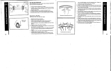
Shimano CP-WH28 Dealer's Manual

Type
Dealer's Manual

This manual is also suitable for

(English)
DM-MAWH002-03
Dealer's Manual
ROAD MTB Trekking
City Touring/
Comfort Bike
URBAN SPORT E-BIKE
Wheel Set
(Disc Brake)
DEORE XT
WH-M8100
WH-M8120
2
CONTENTS
CONTENTS .................................................................................2
IMPORTANT NOTICE ..................................................................4
TO ENSURE SAFETY ...................................................................5
LIST OF TOOLS TO BE USED ......................................................9
INSTALLATION/REMOVAL .......................................................10
Tire size .................................................................................................10
Installing the spoke protector .............................................................10
• CP-WH32 ................................................................................................................................. 10
Installing/removing the cassette sprocket .........................................11
Installing the disc brake rotor .............................................................12
Removing the disc brake rotor ............................................................12
MAINTENANCE ........................................................................13
Spoke tension value .............................................................................13
• WH-M8100 .............................................................................................................................. 13
• WH-M8120 .............................................................................................................................. 13
Replacing the spokes ...........................................................................13
• WH-M8100 .............................................................................................................................. 14
• WH-M8120 .............................................................................................................................. 15
Replacing tubeless tape .......................................................................16
Front hub ..............................................................................................19
• Disassembly ............................................................................................................................. 19
• Assembly ................................................................................................................................. 22
Freehub .................................................................................................23
• Pre-work cautions ................................................................................................................... 23
• Disassembly ............................................................................................................................. 24
• Assembly ................................................................................................................................. 28
Replacing the freewheel body ............................................................33
3
Installing and removing the tubeless tires .........................................33
• Installation .............................................................................................................................. 34
• Removal .................................................................................................................................. 36
• Installing when using an inner tube ..................................................................................... 36
4
IMPORTANT NOTICE
IMPORTANT NOTICE
This dealer's manual is intended primarily for use by professional bicycle mechanics.
Users who are not professionally trained for bicycle assembly should not attempt to
install the components themselves using the dealer's manuals.
If any part of the information on the manual is unclear to you, do not proceed with the
installation. Instead, contact your place of purchase or a distributor for assistance.
Make sure to read all manuals included with the product.
Do not disassemble or modify the product other than as stated in the information
contained in this dealer's manual.
All manuals and technical documents are accessible online at https://si.shimano.com.
For consumers who do not have easy access to the internet, please contact a SHIMANO
distributor or any of the SHIMANO offices to obtain a hardcopy of the User's Manual.
Please observe the appropriate rules and regulations of the country, state or region in
which you conduct your business as a dealer.
For safety, be sure to read this dealer's manual thoroughly before use, and
follow it for correct use.
The following instructions must be observed at all times in order to prevent personal injury
and physical damage to equipment and surroundings.
The instructions are classified according to the degree of danger or damage which may occur
if the product is used incorrectly.
DANGER
Failure to follow the instructions will result in death or serious
injury.
WARNING
Failure to follow the instructions could result in death or
serious injury.
CAUTION
Failure to follow the instructions could cause personal injury or
physical damage to equipment and surroundings.
5
TO ENSURE SAFETY
TO ENSURE SAFETY
WARNING
Be sure to follow the instructions provided in the manuals when installing the product.
Only use SHIMANO genuine parts. If a component or replacement part is incorrectly
assembled or adjusted, it can lead to component failure and cause the rider to lose
control and crash.
Wear approved eye protection while performing maintenance tasks such as
replacing components.
When assembling the freehub body unit, do not apply grease or oil outside of the
designated areas. This may cause the freehub body unit to malfunction.
Do not wash the freehub body unit. The internal grease may flow out and cause the
freehub body unit to malfunction.
Be sure to also inform users of the following:
Check that the wheels are fastened securely before riding the bicycle. Using the axle
release lever incorrectly may cause the wheel to fall off, etc. and lead to serious injury
due to a fall.
Before riding the bicycle, check the wheels to make sure that there are no bent or loose
spokes, dents, scratches or cracks on the rim surface. Do not use the wheel if any of these
problems are found. The wheel may break, and you may fall. Check also that there is no
carbon separation or cracking.
Before riding the bicycle, carefully check the wheels to make sure that there are no
cracks in the axles; if there is any sign of a crack or any other unusual condition, DO NOT
use the bicycle. This wheel is not designed for downhill bicycle riding or freeriding.
Depending on the riding conditions, the wheel axle could develop cracks. This could
result in the failure of the wheel axle, which can lead to an accident resulting in serious
injury or even death.
Do not use with rim brakes. These wheels are designed exclusively for use with disc
brakes. They are not compatible with rim brakes.
6
TO ENSURE SAFETY
Make sure that, even if the axle release lever is tightened as much as possible by hand,
the axle release lever does not interfere with the disc brake rotor. The axle release lever
may interfere with the disc brake rotor if it is on the disc brake rotor side, which is
dangerous. If the axle release lever/quick release lever interferes with the disc brake
rotor, immediately stop use and contact the place of purchase or a distributor.
Axle release
lever
Disc brake rotor
Do not touch the calipers or disc brake rotor while riding or immediately after
dismounting from the bicycle. The calipers and disc brake rotor will become hot when
the brakes are operated, so you may get burned if you touch them. Check that the brake
system has cooled down sufficiently before attempting brake system maintenance.
Read the disc brake manual carefully, and keep it in a safe place for later reference.
The tires should be inflated to the appropriate pressure indicated on the tires or rims
before use. If the maximum pressures indicated on the tires and rims differ, be sure not
to exceed the maximum pressure with the lower value. A higher pressure than indicated
can cause a sudden puncture and/or sudden release of the tire, which can result in serious
injury.
WH-M8100: Maximum pressure = 3 bar / 44 psi / 300 kPa
WH-M8120: Maximum pressure = 2.5 bar / 37 psi / 250 kPa
For details on the E-THRU axle, refer to the E-THRU axle user's manual.
For installation to the bicycle, and maintenance:
When installing the wheel to the front suspension fork/frame, always be sure to follow
the instructions given in the manual for the front suspension fork/frame. The securing
method and tightening torque for the wheel both vary depending on the type of front
suspension fork/frame being used. If the instructions are not followed, the wheel may fall
out of the suspension fork and serious injury may occur. When the front wheel is
tightened onto the front suspension fork/frame in accordance with the tightening torque
in the manual, the wheel's rotation may become stiff; however, the instructions must
always be followed.
CAUTION
For installation to the bicycle, and maintenance:
When installing or removing the rotor lock ring, be careful not to touch the outer edges
of the disc brake rotor with your hands. Wear gloves to protect your hands from getting
cut.
7
TO ENSURE SAFETY
Be sure to also inform users of the following:
If you will be using a puncture repair agent, consult the place of purchase or a
distributor.
Be sure to use tubeless tape when using these wheels.
If you use a tire such as a Tubeless Ready tire that needs to be used with a sealant, use
the sealant recommended by the tire manufacturer.
Burn-in period
Disc brakes have a burn-in period, and the braking force will gradually increase as the
burn-in period progresses. Make sure that you are aware of any such increases in braking
force when using the brakes during the burn-in period. The same thing will happen
when the brake pads or disc brake rotor are replaced.
For installation to the bicycle, and maintenance:
Refer to the tire size table in the INSTALLATION/REMOVAL section when using tires.
Read the tire manual carefully, and keep it in a safe place for later reference.
NOTICE
Be sure to also inform users of the following:
For the use of the supplied nipple wrench tool, contact your place of purchase or a
distributor for their assistance.
Do not add oil to the internal parts of the hub. Otherwise, grease will flow out.
It is recommended that you ask a place of purchase to adjust the spoke tensions if there
is any deviation in the spokes and after the first 1,000 km of riding.
Optional reflector and spoke protector sets are available. Check the model number on
the website specifications and please ask your bicycle dealer for details.
Do not use detergent or other chemicals when wiping the wheel, otherwise, the sticker
on the rim may come off.
Products are not guaranteed against natural wear and deterioration from normal use
and aging.
For maximum performance we highly recommend SHIMANO lubricants and maintenance
products.
8
TO ENSURE SAFETY
For installation to the bicycle, and maintenance:
Use of genuine SHIMANO spokes, nipples, and washers is strongly recommended.
Otherwise, the area where the spokes fit into the hub body may become damaged.
Be careful not to overtighten the nipples when adjusting the spoke tensions. If
overtightened, damage to the rim may result.
If the wheel becomes stiff and difficult to turn, apply grease.
If the freehub is making abnormal noises when the pedal is pressed, the spacer may need
more grease. Apply grease to the spacer.
Special nipple wrenches are available as optional accessories.
Check the specifications table (https://si.shimano.com) for compatible reflectors and
spoke protectors.
For information on how to install and remove the tires, refer to the manual
accompanying the tire.
The actual product may differ from the illustration because this manual is
intended mainly to explain the procedures for using the product.
9
LIST OF TOOLS TO BE USED
The following tools are needed for installation/removal, adjustment, and maintenance
purposes.
Tool
17 mm hub spanner
18 mm hub spanner
22 mm hub spanner
TL-FH16
TL-FC36
Snap ring remover
Slotted screwdriver
10
INSTALLATION/REMOVAL
Tire size
INSTALLATION/REMOVAL
Tire size
The recommended tire sizes for installation to each wheel are as follows.
Series Wheel size Model No. Tire size
DEORE XT
622 x 24C (29")
WH-M8100-TL-F15-B-29
29 x 2.00 - 2.35
WH-M8100-TL-R12-B-29
622 x 30C (29")
WH-M8120-TL-F15-B-29
29 x 2.25 - 2.50
WH-M8120-TL-R12-B-29
584 x 24C (27.5")
WH-M8100-TL-F15-B-275
27.5 x 2.00 - 2.35
WH-M8100-TL-R12-B-275
584 x 30C (27.5")
WH-M8120-TL-F15-B-275
27.5 x 2.25 - 2.50
WH-M8120-TL-R12-B-275
Installing the spoke protector
For information on wheels that can be installed, check the compatibility information (https://
productinfo.shimano.com).
CP-WH32
1. Install the pins to the spoke protector.
11
INSTALLATION/REMOVAL
Installing/removing the cassette sprocket
NOTICE
For the pin installation position, refer to the following. There is a datum hole
between the SHIMANO logo and the model name.
Datum hole
2. Install the spoke protector.
Push the pins onto the outer spokes to install.
Installing/removing the cassette sprocket
Refer to the dealer's manual for the cassette sprocket to install/remove the cassette sprocket.
12
INSTALLATION/REMOVAL
Installing the disc brake rotor
1. Set the disc brake rotor on the hub, and then secure it with the disc
brake rotor lock ring.
Use TL-FC36 to secure it.
40 N·m
Disc brake rotor lock ring
External spline type
Disc brake rotor lock ring
Lock ring tightening tool TL-FC36
Removing the disc brake rotor
Perform the removal of the disc brake rotor in the reverse order from the installation
procedure.
13
MAINTENANCE
Spoke tension value
MAINTENANCE
Spoke tension value
NOTICE
Use SHIMANO original tools (for the front: TL-HB16, for the rear: TL-FH12) when
assembling the wheel.
WH-M8100
* Refer to the table for spoke tension value.
Number of spokes: 28
Spoke tension value
For front For rear
Left side
(disc brake rotor side)
704 - 954 N
29": 650 - 866 N
27.5": 750 - 970 N
Right side 650 - 895 N
29": 910 - 1,160 N
27.5": 1050 - 1,300 N
WH-M8120
* Refer to the table for spoke tension value.
Number of spokes: 28
Radial lacing is not supported.
Spoke tension value
For front For rear
Left side
(disc brake rotor side)
975 - 1,192 N 815 - 1,042 N
Right side 972 - 1,188 N 866 - 1,103 N
Replacing the spokes
Remove the tubeless tape before replacing the spokes.
(For instructions on attaching/removing tubeless tape, refer to “Replacing tubeless tape”.)
14
MAINTENANCE
Replacing the spokes
WH-M8100
1. Pass the spoke through the washer.
Spoke
Washer
NOTICE
Direct the convex side of the washer toward the hole in the hub flange when
passing the spoke through the washer.
2. Insert the spoke through the hole in the hub flange.
Hub flange
Spoke
Washer
15
MAINTENANCE
Replacing the spokes
3. Attach the nipple and washer, and tighten the spoke with the specified
tension.
Nipple
Washer
4. Remove the dirtiness from the rim hole and where the tubeless tape
will be affixed.
WH-M8120
1. Insert the spoke through the hole in the hub flange.
16
MAINTENANCE
Replacing tubeless tape
2. Attach the nipple and tighten the spoke with the specified tension.
Nipple
3. Remove the dirtiness from the rim hole and where the tubeless tape
will be affixed.
Replacing tubeless tape
1. Wipe away the sealant.
* Only while using sealant
17
MAINTENANCE
Replacing tubeless tape
2. Remove the tubeless tape.
NOTICE
The tubeless tape cannot be reused, so use a new one after replacing it.
Use a tubeless tape matching the rim width.
It is recommended to use genuine SHIMANO tubeless tape to prevent punctures
and other possible damage.
Tubeless tape
3. Remove the dirtiness from the rim surface where the tape will be
affixed.
18
MAINTENANCE
Replacing tubeless tape
4. Affix new tubeless tape.
Start affixing the tubeless tape from the opposite side of the valve.
TECH TIPS
As the tape may tear, do not use a tool (use your
hand) to affix the tape. Pull the tape with your hand
to some extent when affixing it.
Affix the tubeless tape in the middle of the rim, not off
to one side, as shown in the figure.
5. Securely attach both ends of the tape to the rim.
* Overlap the ends of the tape by approximately 10 cm.
Approximately
10 cm
19
MAINTENANCE
Front hub
6. Drill a pilot hole in the valve hole section and then attach the valve.
Valve hole section
Valve
Ø approximately 3 mm
Front hub
Disassembly
1. Remove the cap using a tool such as a slotted screwdriver.
Cap
20
MAINTENANCE
Front hub
2. Loosen the lock nut on the double-lock section on the right side of the
hub body.
The hub cannot be disassembled from the left side of the hub body (the disc brake rotor
fixing spline side).
Lock nut
  • Page 1 1
  • Page 2 2
  • Page 3 3
  • Page 4 4
  • Page 5 5
  • Page 6 6
  • Page 7 7
  • Page 8 8
  • Page 9 9
  • Page 10 10
  • Page 11 11
  • Page 12 12
  • Page 13 13
  • Page 14 14
  • Page 15 15
  • Page 16 16
  • Page 17 17
  • Page 18 18
  • Page 19 19
  • Page 20 20
  • Page 21 21
  • Page 22 22
  • Page 23 23
  • Page 24 24
  • Page 25 25
  • Page 26 26
  • Page 27 27
  • Page 28 28
  • Page 29 29
  • Page 30 30
  • Page 31 31
  • Page 32 32
  • Page 33 33
  • Page 34 34
  • Page 35 35
  • Page 36 36
  • Page 37 37
  • Page 38 38

Shimano CP-WH28 Dealer's Manual

Type
Dealer's Manual
This manual is also suitable for

Ask a question and I''ll find the answer in the document

Finding information in a document is now easier with AI