Page is loading ...

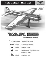
decathlon - EP
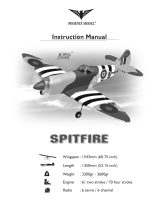
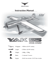
Instruction Manual
Wingspan : 1300mm (51.2 in)
Length : 980mm (38.6 in)
Weight : 1600g - 1800g
Engine : AXI motor 2814 or 2820
Radio : 4 channel / 3 servo
g
The Decathlon - EP is a semi-scale model aircraft for electric motor. Displaying smooth
and stable flight characteristics, The Decathlon - EP offers electric power's convenience
together with exciting, semi-scale looks. Most parts are cut by LASER machine. Quality
wood construction - covered with ORACOVER . Factory painted cowl - 95% almost
ready to fly. Most hardware included and all replacement parts are available.

KIT CONTENTS: We have organized the parts as they come out of the box for better
identification during assembly. We recommend that you regroup the parts in the same
manner. This will ensure you have all of parts required before you begin assembly
AIR FRAME ASSEMBLIES
. (2) Wing halves with ailerons
. (1) Fuselage with canopy.
. (1) Horizontal stabilizer with elevator halves
. (1) Vertical stabilizer with rudder
. (1) Motor cowl
. (1) Decal sheet
. (1) Instruction manual
MAIN GEAR ASSEMBLY
. (2) Main gears
. (2) 42mm diameter wheels
. (2) Wheel pant
. (2) Alxe
. (4) Nut
. (4) Wheel collars
. (4) 3m flat washer
. (8) 6m flat washer
. (4) 3mm x 12mm screw
. (4) 3m flat washer
TAIL GEAR ASSEMBLY
. (1) Tail gear
. (1) 25mm diameter wheel
. (1) Wood collar
. (1) 2mm collar
. (2) 2mm x 12mm wood screw
. (4) Wood clasp
ELEVATOR CONTROL SYSTEM
. (1) Control horn
. (2) 2mm x 12mm wood screw
. (1) Metal connector
. (1) Wire metal rod (120mm)
RUDDER CONTROL SYSTEM
. (1) Control horn
. (2) 2mm x 12mm wood screw
. (1) Metal connector
. (1) Wire metal rod (120mm)
AILERON CONTROL SYSTEM
. (2) Control horn
. (4) 2mm x 16mm wood screw
. (2) Metal connector
. (2) Wire metal rod (120mm)
. (8) 2mm x 10mm wood screw
MOTOR MOUNT ASSEMBLY
. (1) Engine mount
. (4) 3mm x 15mm wood screw
. (4) 6m flat washer
. (3) Wood plate (50mm)
MISCELLANEOUS ITEMS
. (1) Dihedral
. (6) 4mm x 30mm nylon screw
. (4) 2.6mm x 10mm wood screw
. (2) Wing strut
. (6) 3mm x 15mm wood screw
. (6) 6m flat washer
. (1) Cowling
KIT CONTENTS
1

TOOLS AND SUPPLIES NEEDED
• Medium C/A glue
• 30 minute epoxy
• 6 minute epoxy
• Hand or electric drill
• Assorted drill bits
• Modeling knife
• Straight edge ruler
• 2 bender plier
• Wire cutters
• Masking tape
• Thread lock
• Paper towels
• Rubbing alcohol
SUGGESTION
To avoid scratching your new airplane, do not unwrap
the pieces until they are needed for assembly. Cover
your workbench with an old towel or brown paper,
both to protect the aircraft and to protect the table.
Keep a couple of jars or bowls handy to hold the
small parts after you open the bag.
NOTE:
Please trial fit all the parts. Make sure you have the
correct parts and that they fit and are aligned properly
before gluing! This will assure proper assembly. The
DECATHLON EP is hand made from natural
materials, every plane is unique and minor
adjustments may have to be made. However, you
should find the fit superior and assembly simple.
The painted and plastic parts used in this kit are fuel
proof. However, they are not tolerant of many harsh
chemicals including the following: paint thinner, C/A
glue accelerator, C/A glue debonder and acetone. Do
not let these chemicals come in contact with the
colors on the covering and the plastic parts.
SAFETY PRECAUTION:
• This is not a toy
• Be sure that no other flyers are using your radio
frequency.
• Do not smoke near fuel
• Store fuel in a cool, dry place, away from
children and pets.
• Wear safety glasses.
• The glow plug clip must be securely attached to
the glow plug.
• Do not flip the propeller with your fingers.
• Keep loose clothing and wires away from the propeller.
• Do not start the engine if people are near. Do not
stand in line with the side of the propeller.
• Make engine adjustments from behind the propeller
only. Do not reach around the spinning propeller.
2
PREPARATIONS
Remove the tape and separate the ailerons
from the wing and the elevators from the stab.
Use a covering iron with a covering sock on
high heat to tighten the covering if necessary.
Apply pressure over sheeted areas to
thoroughly bond the covering to the wood.
INSTALLING THE AILERONS
1. Test fit the ailerons to the wing with the hinges.
If the hinges don’t remain centered, stick a pin
through the middle of the hinge to hold it in
position.
1
TEMPORARY PIN
TO KEEP HINGE
CENTERED
2
CA glue
2. Apply six drops of thin CA to the top and bottom
of each hinge. Do not use CA accelerator. After
the CA has fully hardened, test the hinges by
pulling on the aileron.

3
3. Place the servo into the servo tray. Center the
servo within the tray and drill 1,6mm pilot holes
through the block of wood for each of the four
mounting screws provided with the servo.
Remove the covering
3
INSTALLING THE AILERON SERVOS
1. Install the rubber grommets and brass eyelets
onto the aileron servo.
2. Using a modeling knife, remove the covering
from over the pre-cut servo arm exit hole on the
aileron servo tray / hatch. This hole will allow
the servo arm to pass through when installing
the aileron pushrods.
4
5
5. Place the aileron servo tray / hatch into the
servo box on the bottom of the wing and drill
1,6mm pilot holes through the tray and the
servo box for each of the four mounting screws.
Secure the servo tray in place using the
mounting screws provided ( 2mm x 12mm ).
6. Repeat step # 2 - # 5 to install the second
aileron servo in the opposite wing half.
7. Using masking tape, tape the servo leads on to
the top of the wing.
4. Using the thread as a guide and using masking
tape, tape the servo lead to the end of the
thread: carefully pull the thread out. When you
have pulled the servo lead out, remove the
masking tape and the servo lead from the
thread.
Servo lead
6
INSTALLING THE CONTROL HORNS
1. One aileron control horn in positioned on each
aileron. Using a ruler and a pen, locate and
mark the location of the control horn. It should
be mounted on the bottom side of the aileron at
the leading edge, in line with the aileron
pushrod.
2. Drill two holes through the aileron using the
control horn as a guide and screw the control
horn in place.
7
To the cowl
8
To the cowl

4
9
10
5. Repeat step # 1 - # 4 to install the second
aileron linkage. After both linkages are
completed, connect both of the aileron servo
leads using a Y-harness you have purchased
separately.
12
11
3. Repeat step # 1 - # 2 to install the control horn
on the opposite aileron.
1. Attach the pushrod to the outer hole in the
control horn and slide it through the metal
connector.
2. Locate one nylon servo arm, and using wire
cutters, remove all but one of the arms. Using a
2mm drill bit, enlarge the third hole out from the
center of the arm to accommodate the aileron
pushrod wire.
3. Plug the aileron servo into the receiver and
center the servo. Install the servo arm onto the
servo. The servo arm should be perpendicular
to the servo and point toward the middle of the
wing.
4.
Center the aileron and secure the metal connector.
INSTALLING THE AILERON LINKAGES
RIGHT WRONG
13
Screw
Machine screw
Metal connector
Screw
M3 Nut
M3 Nut
Servo arm
INSTALLING THE WING TO THE FUSELAGE
Attach the wings to the joiner tube and using the
nylon thumbscrews to secure the wing panels
to the fuselage.

5
Draw a center line
15
3. Check the fit of the horizontal stabilizer in its
slot. Make sure the horizontal stabilizer is
square and centered to the fuselage by taking
measurements, but don't glue anything yet.
4. With the horizontal stabilizer correctly aligned,
mark the shape of the fuselage on the top and
bottom of the tail plane using a water soluble /
non-permanent felt-tip pen.
!
5. Remove the stabilizer. Using the lines you just
drew as a guide, carefully remove the covering
from between them using a modeling knife.
When cutting through the covering to remove it,
cut with only enough pressure to only cut
through the covering it's self. Cutting into the
balsa structure may weaken it. This could lead
to possible failure during flight.
2. Draw a center line onto the horizontal stabilizer.
16
6. When you are sure that everything is aligned
correctly, mix up a generous amount of 30
minute epoxy. Apply a thin layer to the top and
bottom of the stabilizer mounting area and to
the stabilizer mounting platform sides in the
fuselage. Slide the stabilizer in place and
re-align. Double check all of your
measurements one more time before the epoxy
cures. Remove any excess epoxy using a
paper towel and rubbing alcohol and hold the
stabilizer in place with T-pins or masking tape.
17
Remove the covering
18
Glue with epoxy
7. After the epoxy has fully cured, remove the
masking tape or T-pins used to hold the
stabilizer in place and carefully inspect the glue
joints. Use more epoxy to fill in any gaps that
were not filled previously and clean up the
excess using a paper towel and rubbing alcohol.
HORIZONTAL STABILIZER INSTALLATION
1. Using a modeling knife, cut away the covering
from the fuselage for the stabilizer and remove it.
14

6
VERTICAL STABILIZER INSTALLATION
1. Using a modeling knife, remove the covering on
the top of the fuselage for the vertical stabilizer.
8. Repeat step # 1 - # 2 from installing the ailerons
to install the elevator.
6. Repeat step # 1 - # 2 from installing the ailerons
to install the rudder.
2. Slide the vertical stabilizer into the slot in the
mounting platform in the top of the fuselage.
Mark the shape of the fuselage on the left and
right sides of the vertical stabilizer using a
felt-tip pen.
3. Now, remove the vertical stabilizer and using a
modeling knife, carefully cut just inside the
marked lines and remove the film on both sides
of the vertical stabilizer. Just as you did with the
horizontal stabilizer, make sure you only press
hard enough to cut the film, not the balsa
vertical stabilizer.
19
Glue with epoxy
20
Remove
the covering
21
Remove the covering
22
4. Slide the vertical stabilizer back in place. Using
a triangle, check to ensure that the vertical
stabilizer is aligned 90 degree to the horizontal
stabilizer.
5. When you are sure that everything is a aligned
correctly, mix up a generous amount of 30
minute epoxy. Apply a thin layer to the slot in
the mounting platform and to the vertical
stabilizer mounting area. Apply epoxy to the
lower rudder hinge. Set the stabilizer in place
and re-align. Double check all of your
measurements once more before the epoxy
cures. Remove any excess epoxy using a
paper towel and rubbing alcohol and hold the
stabilizer in place with T-pins or masking tape.
Allow the epoxy to fully cure before proceeding.
Hinge
23
Glue with epoxy
24

3. Using a modeling knife, carefully cut out two line
from the margin of the hole onto the wheel pant.
Just cut only one side of the wheel pant, where
the main gear will install. Be sure to make a left
and right wheel pant.
4. Slide a 4.5mm nut/ two 16mm flat washers /
4.5mm nut / collar / wheel / collar onto the axle.
5. Slide the axle assembly into the wheel pant.
There are just one nut and two flat washers
outside of the wheel pant.
6. Remove one nut, one flat washer. Attach the
main landing gear to the axle.
7. Center both collars and wheel in the middle of
the wheel pant, lock both collars in place using
a hexagon 2mm screw.
8. With the landing gear in place, tighten two nuts.
28
6mm flat washer
! After installing the wheel pant, apply a small
drop of thin C/A to the bottom nut.
9. Repeat step # 1-8 to install the second wheel
pant assembly.
MAIN GEAR INSTALLATION
INSTALLING THE MAIN LANDING GEAR
1. Four nuts have been installed at the factory.
2. Install main landing gear into the fuselage using
(4) 4mm x 20mm machine screws and 16mm
flat washers provided in the kit.
7
Screws
Glue with epoxy
26
Glue with epoxy
25
TAIL WHEEL INSTALLATION
1. Set the tail wheel assembly in place on the
plywood plate.
2.
Drill 2,6mm pilot holes through the plywood plate.
3. Secure the tail wheel bracket in place using two
3mm x 12mm screw.
4. Align the tail wheel wire so that the wire is
parallel with the bottom of the rudder. The
control clasp has a pre-drilled hole through the
top of it. Slide this hole on to the tail wheel wire
while sliding the clasp over the bottom of the
rudder.
!
Drill Cut
27
INSTALLING THE WHEEL PANTS
1. Locate the wheel pants from the hardware bag.
Mark the locations of the mounting axles onto
the wheel pants. The locations of the two
mounting holes are the middle of the wheel
opening, on right side, left side and 10mm from
the bottom of the wheel pant.
2. Using a 5mm drill bit, carefully drill two pilot
holes through the wheel pant at the TWO
marks you made.

8
29 32
30
Remove the covering
31
SERVO INSTALLATION
INSTALLING THE FUSELAGE SERVOS
1. Install the rubber grommets and brass collets
into the elevator, rudder and throttle servos.
Test fit the servos into the servo tray. Trim the
tray if necessary to fit your servos
2. Mount the servos to the tray using the mounting
screws provided with your radio system.
INSTALLING THE ELEVATOR linkages
Repeat step # 1 - # 4 from installing the aileron
linkages to install the elevator linkages.
INSTALLING THE rudder linkages
Repeat step # 1 - # 4 from installing the aileron
linkages to install the rudder linkages.
35
Control horn
34
Control horn elevator
33
Control horn elevator


11
BALANCING
1. It is critical that your airplane be balanced
correctly. Improper balance will cause your
plane to lose control and crash.
THE CENTER OF GRAVITY IS LOCATED 55mm
BACK FROM THE LEADING EDGE OF THE
WING, AT THE FUSELAGE.
2. Mount the wing to the fuselage. Using a couple
of pieces of masking tape, place them on the
top side of the wing 55mm back from the
leading edge, at the fuselage sides.
3. Turn the airplane upside down. Place your
fingers on the masking tape and carefully lift
the plane.
4. If the nose of the plane falls, the plane is heavy
nose. To correct this first move the battery pack
further back in the fuselage. If this is not
possible or does not correct it, stick small
amounts of lead weight on the fuselage under
the horizontal stabilizer. If the tail of the plane
falls, the plane is tail heavy. To correct this,
move the battery and receiver forward or if this
is not possible, stick weight into the firewall.
When balanced correctly, the airplane should
sit level or slightly nose down when you lift it up
with your fingers.
55mm
Ailerons : 12mm up 12mm down
Elevator : 12mm up 12mm down
Rudder : 15mm right 15mm left
Elevator Control
Aileron Control
12mm
12mm
Rudder Control
15mm
15mm
12mm
12mm
LATERAL BALANCE
After you have balanced a plane on the C.G.
You should laterally balance it. Doing this will
help the airplane track straighter.
1. Turn the airplane upside down. Attach one loop
of heavy string to the engine crankshaft and
one to the tail wheel wire. With the wings level,
carefully lift the airplane by the string. This may
require two people to make it easier.
2. If one side of the wing fall, that side is heavier
than the opposite. Add small amounts of lead
weight to the bottom side of the lighter wing
half's wing tip. Follow this procedure until the
wing stays level when you lift the airplane.
CONTROL THROWS
1. We highly recommend setting up a plane using
the control throws listed.
2. The control throws should be measured at the
widest point of each control surface.
3. Check to be sure the control surfaces move in
the correct directions.
!
53
Screw
54
INSTALLING THE WING STRUT
1. Screw the wing strut into the fuselage.
52
Screw
2. Screw the wing strut into the wing
3. Finishing.

12
FLIGHT PREPARATION PRE FLIGHT CHECK
1. Completely charge your transmitter and receiver
batteries before your first day of flying.
2. Check every bolt and every glue joint in your
plane to ensure that everything is tight and well
bonded.
3. Double check the balance of the airplane
4. Check the control surface
5. Check the receiver antenna . It should be fully
extended and not coiled up inside the fuselage.
6. Properly balance the propeller.

Metric Conversions
I/C FLIGHT WARNINGS
Inches x 25.4 = mm (conversion factor)
1/64" = .4 mm 3/16" = 4.8 mm 1" = 25.4 mm 21" = 533.4 mm
1/32" = .8 mm 1/4" = 6.4 mm 2" = 50.8 mm 24" = 609.6 mm
1/16" = 1.6 mm 3/8" = 9.5 mm 3" = 76.2 mm 30" = 762.0 mm
3/32" = 2.4 mm 1/2" = 12.7 mm 6" = 152.4 mm 36" = 914.4 mm
1/8" = 3.2 mm 5/8" = 15.9 mm 12" = 304.8 mm
5/32" = 4.0 mm 3/4" = 19.0 mm 18" = 457.2 mm
13

I/C FLIGHT GUIDELINES
Made in Vietnam
When ready to fly, first extend the
transmitter aerial.
Operate the control sticks on the
transmitter and check that the control
surfaces move freely and in the
CORRECT directions. ALWAYS land the model INTO the
wind, this ensures that the model lands
at the slowest possible speed.
Switch on the transmitter.
Switch off the transmitter.
Check that the transmitter batteries
have adequate power.
Switch off the receiver.
Switch on the receiver. ALWAYS take off into the wind.
Check that the wings are correctly
fitted to the fuselage. If the model does not respond correctly
to the controls, land it as soon as
possible and correct the fault.
Empty the fuel tank after flying, fuel left
in the tank can cause corrosion and
lead to engine problems.
/