Page is loading ...

USR-GPRS-MODEM user manual www.tcp232.net
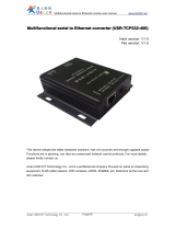
USR-GPRS-MODEM user manual
Hardware version : V1.0
File version : V1.0
This equipment is industrial-strength GPR S -MODEM
,
c ommonly known as "SMS cat"
.
Mainly used for
customers demand of wireless data business, to combine with computer software to realize SMS notification or
combine with embedded system to realize SMS alarm or remote data transmission.
Jinan USR IOT Technology Co., Ltd professional focus ed on serial to ethernet equipment, RJ45 network,
WIFI, GPRS and ZIGBEE modules. We can customiz e network control products. For more details, contact us
freely
.

USR-GPRS-MODEM user manual www.tcp232.net
1. Product introduction :
USR- GPRS-MODEM built-in four frequency GSM/GPRS industrial-strength module, provide standard
RS232 interface, can be directly connec ted to equipment
.
Through the terminal based on global GSM network
access to equipment
,
wireless access to Internet, so realiz e data transparent transmission.
When u sed for GSM SMS sending, the equipment can integrate with all kinds of OA system
.
When used
to send notice s and fault alarm message s, we can provides direct available SMS sending software and
secondary development control s
.
When u sed for GPRS data transmission, this device is the value-added solutions M2M application
.
A ppl y
to vehicle, industrial-strength PDA, personal tracking, wireless POS, intelligent metering, weather, digital
medical treatment, telemetry, military, space exploration, agriculture, forestry, water, coal mine,
petrochemical and other fields, to provide perfect GSM/GPRS SMS, data transmission service.
1.1 C haracteristics
�
Using the high performance four frequency industrial-strength wireless module
�Embedded reliable TCP / IP network protocol
�
Stab le usb flash disk protection mechanism
�General RS232 interface
�
Support 3v, 1v8 SIM card
�Can realize messaging and CSD services
�
EMF-RFI and good shell packaging
�Use simple AT command interface
�C ore module through CE and FCC certification

USR-GPRS-MODEM user manual www.tcp232.net
1.2 Technical specifications :
Main features P arameters
Power supply voltage DC: 5~18V
Frequency band
Support four frequency :
GSM850, GSM900, DCS1800, PCS1900
Frequency automatic search
Frequency can be set by AT command
C orrespond with GSM Phase2/2+
AT command GSM 07.07, GSM 07.05 a nd other exten ded AT command
Transmitting power
Class4 (2W): GSM850 and GSM900
Class2 (1W): DCS1800 and PCS1900
GPRS
data characteristic
GPRS upward transmission rate : MAX 85.6kbps
GPRS descending transmission rate : MAX 85.6kbps
Cod ed format : CS-1
,
CS-2
,
CS-3
,
CS-4
Support PAP ( password validation) agreement which is used for
PPP connection
Built-in agreement; TCP/UDP/FTP/PPP, etc
Support packet broadcast control channel( PBCCH)
CSD Circuit switching
CSD transmission rate: 2.4,4.8,9.6, 14.4 kbps
Not t ransparent transmission
Support unstructured supplementary service data( USSD)
M essage
Text and PDU mode
M essage storage equipment: SIM card
RS232 characteristic
Global function serial port
Used for AT command, GPRS and CSD data transmission
Adaptive baud rate : 4800 bps - 115200 bps
Character format : data bit 8
,
stop bit 1
,
no parity bit
Temperature range
Working temperature : -35 to 80 ℃
Storage temperature : -40 to 80 ℃
Hardware interface Specifications
Power
A power socket
S tandard size : Out er diameter 5.5 mm
,
inner diameter 2.1 mm ;
inner + external -; input voltage range 5 ~ 18 v
RS232 interface A RS232 standard interface ( device is female )
SIM card interface
A SIM card interface
Support 3 v/ 1v 8 SIM c ard
Antenna interface A standard SMA interface
Warranty 2 years
1.
3 P ackage:
USR-GPRS-MODEM includ ing the following parts :

USR-GPRS-MODEM user manual www.tcp232.net
�USR-GPRS-MODEM * 1
�GPRS antenna (SMA interface) * 1
�5v power adapter * 1
�Serial cable* 1
�User guide CD * 1
2 . USR- GPRS-MODEM I nstallation :
2.1 USR- GPRS-MODEM Installation S ize
USR- GPRS-MODEM is pack aged in metal casing, can be used independently, with fixed hole, convenient for
user installation.
Physical size
85mm x 50mm x 26mm
( without interface )
Overall size
95mm x 50mm x 26mm
(i ncluding interface )
W eight 140 grams
S hell
Metal shell
strong anti-jamming ability
USR-GPRS-MODEM
i
nternal module as below :
Corresponding dimension s as below, the unit is mm
.

USR-GPRS-MODEM user manual www.tcp232.net
2.2 USR- GPRS - MODEM antenna installation
USR- GPRS-MODEM antenna plug use 50 Ω SMA connector, tight the antenna a s clockwise
.
2.3 USR- GPRS-MODEM SIM card install ation
The SIM card adopt self-popup SIM holder, the SIM card chip face down, shortcorner of card toward the
GPRS-MODEM
,
then gently push SIM holder interface
.
Push the SIM holder w hen you want to remove SIM
card
.
Note :
You mustn ’ t plug or get out the SIM card when the device power on.
2.4 USR-G PRS-MODEM pin definition
USR- GPRS-MODEM serial is female DB9 interface, the standard DB9 pin sort as below :
Female Male
USR- GPRS-MODEM RS 232 pin defin itions as follows :

USR-GPRS-MODEM user manual www.tcp232.net
Pin Numbers Pin definition
1 Carrier detect
2 Send data
3 Receiv e data
4 DTE ready
5 Land
6
7 DTE require to send data
8 Clear sending
9 ringing
2.5 USR-GPRS-MODEM power
This device can use 5~ 18v wide range voltage power supply. Instantaneous current will be very large in
wireless communication, and change rapidly, so the external power resistance should be as low as possible.
Note :The power supply plug polarity is internal “ + ” external “ - ”
,
power polarity error will lead the device
and power supply equipment to serious damage.
2.6 USR- GPRS - MODEM stat us indicator light
Indicator light Working stat us
WORK
Normally bright, module in
working state
LINK
F licker
,
GPRS service connection
success
TXD,RXD
F licker
,
send and receive data
3. USR- GPRS-MODEM use
First
,
confirm local computer communication port can work and the port attribute. If using a USB to serial
cable connected to the computer USB interface, serial number need confirmed through the following steps :
Open the control panel- my computer- properties - hardware- device manage ment
,
click "+" on the left of port,
unfold port list, device name will show the corresponding serial number as below :
Note :Beside the device name
,
if there is "!" o r "X", it means the equipment installation is ab normal, please

USR-GPRS-MODEM user manual www.tcp232.net
check and execute the above steps again
.
Reminding: Need to install USB to RS232 driver on computer
3.1 Software application
3.1.1 Enterprise SMS software application
Operat e the "Edison messages pass. EXE" file in CD
,
and install (can adopt the default s ettings). After
installation complete d
,
you can see enterprise message application software on the desktop, click can enable.
This software can realize real-time sending of SMS, fixed timing, cycle or group transmission. Message
content can be hand typed
,
insert phrase, database file ( *.xls, *.txt, *.csv, *.mdb
,
etc.), and ODBC data.
Instant messag es send interface as below:
3.1.2 Super terminal application
Open the Windows super terminal, establish a new connection. Choose computer serial interface number
(local real serial port or USB equipment corresponding serial port found out from the device manager ) which is
used to connect USR- GPRS-MODEM
.

USR-GPRS-MODEM user manual www.tcp232.net
Configurat e this computer serial port parameters, these parameters should be correspond with USR-
GPRS-MODEM serial interface parameter, USR- GPRS-MODEM default com parameters are as follows:
baud rate 115200, data bit 8
,
check bit no
,
stop bit 1
,
hardware flow control no.
After s uper terminal configuration completed and operating normally
,
power on USR- GPRS-MODEM. USR-
GPRS-MODEM finish ed starting process, type AT in the following interface and it should show OK, now means
connection success, can continue USR- GPRS-MODEM setting and application
.

USR-GPRS-MODEM user manual www.tcp232.net
3. 1 . 3 S erial debugging tools application
Open the serial debugging software in CD
,
the left side is serial debugging assistant,
the right side is network debugging assistant. Use the local serial connection, only apply the serial debugging
assistant when use AT command
.


USR-GPRS-MODEM user manual www.tcp232.net
OK
1. First of all, make sure your hardware is correct, the method is to input AT, press Enter and send to
module, will receive AT Enter OK; according different setting, you may receive ok only, but no at, then you
can send ATE1 to set echoes command.
2. Send AT+CMGF=1 means to send SMS in text mode, received command to back to and ok.
3. AT+CMGS="+86xxxxxxxxxxx" the cell phone number which sent to, received command to back and ok,
receive message input prompt ">"
4. Input the messages to send, only ASCII code
5. Send CTRL+Z or hexadecimal 0x1A, received the end tip symbol " "
6. Send enter, return ok, send complete.
3.3 Use AT command to realize GPRS connection
Use debugging assistant, realize GPRS connection.
USR- GPRS-MODEM AT command to realize GPRS connection explanation:
AT+QIOPEN="TCP ”
,
"180.168.12.99 ”
,
8877
OK
CONNECT OK
AT+QISEND
> test msg
(CTRL+Z = 0x1A)
SEND OK
AT+QICLOSE
CLOSE OK
1. First of all, make sure your hardware is correct, the method is to input AT, press Enter and send to
module, will receive AT Enter OK; according different setting, you may receive ok only, but no at, then you
can send ATE1 to set echoes command
.
2. AT+QIOPEN="TCP", "180.168.12.99", 8877 means to establish TCP connection, and show module
remote server IP address
,
port number, receive command back and OK, CONNECT OK
3. AT+QISEND
,
send TCP data, received command to back and ok, receive message input prompt ">"
4. Input contents to send
5. Send CTRL+Z or hexadecimal 0x1A, receive SEND OK
6. AT+QICLOSE means close TCP connections, receive command to back and CLOSE OK

/