Page is loading ...

MODEL 140 - Manual/150 - Power
Single Sliding Fiberglass Door
MANUAL PART #: A

ASI DOORS, INC. (800) 558-7068 asidoors.com
GENERAL
INFORMATION
GENERAL INFORMATION
. . . . . . . . . . . . . . . . . . . . . . . 3-6
Safety Practices . . . . . . . . . . . . . . . . . . . . . . . . . . . . . . . . . . . . 4
Warranty Policy . . . . . . . . . . . . . . . . . . . . . . . . . . . . . . . . . . . . 5
Crates and Contents . . . . . . . . . . . . . . . . . . . . . . . . . . . . . . . . . . 6
- INSTALLATION
. . . . . . . . . . . . . . . . . . . . . . . . 7-30
140 LXP Manual
Door Measurements . . . . . . . . . . . . . . . . . . . . . . . . . . . . . . . . . . 7
Frame and Header Assembly . . . . . . . . . . . . . . . . . . . . . . . . . . . . . . 8
Panel Installation & Adjustment . . . . . . . . . . . . . . . . . . . . . . . . . . . . . 10
150 LXP Power
Door Measurements . . . . . . . . . . . . . . . . . . . . . . . . . . . . . . . . . . . 12
Frame and Header Assembly . . . . . . . . . . . . . . . . . . . . . . . . . . . . . . 13
Panel Install & Adjustment . . . . . . . . . . . . . . . . . . . . . . . . . . . . . . . 16
Warning Label Installation . . . . . . . . . . . . . . . . . . . . . . . . . . . . . . . 17
Electrical Controls . . . . . . . . . . . . . . . . . . . . . . . . . . . . . . . . . . . 18
Electrical Equipment . . . . . . . . . . . . . . . . . . . . . . . . . . . . . . . . . . 22
Start-Up . . . . . . . . . . . . . . . . . . . . . . . . . . . . . . . . . . . . . . . . 23
Activator Signals . . . . . . . . . . . . . . . . . . . . . . . . . . . . . . . . . . . . 25
Programming Parameter Codes . . . . . . . . . . . . . . . . . . . . . . . . . . . . . 26
MAINTENANCE
. . . . . . . . . . . . . . . . . . . . . . . . . . . . 30-33
Inspection . . . . . . . . . . . . . . . . . . . . . . . . . . . . . . . . . . . . . . . 30
Preventative . . . . . . . . . . . . . . . . . . . . . . . . . . . . . . . . . . . . . . 30
Troubleshooting . . . . . . . . . . . . . . . . . . . . . . . . . . . . . . . . . . . . 31
General Fault Table . . . . . . . . . . . . . . . . . . . . . . . . . . . . . . . . . . . 31
Electrical Fault Table . . . . . . . . . . . . . . . . . . . . . . . . . . . . . . . . . . 32
REPLACEMENT PARTS
. . . . . . . . . . . . . . . . . . . . . . . 34-56
Instructions for Ordering . . . . . . . . . . . . . . . . . . . . . . . . . . . . . . . . 34
Door Identification . . . . . . . . . . . . . . . . . . . . . . . . . . . . . . . . . . . 35
ID Tag Location . . . . . . . . . . . . . . . . . . . . . . . . . . . . . . . . . . . . . 35
Door Assembly . . . . . . . . . . . . . . . . . . . . . . . . . . . . . . . . . . . . . 36
Header Assembly and Shrouds . . . . . . . . . . . . . . . . . . . . . . . . . . . . . 37
Molded Door Panel Assembly . . . . . . . . . . . . . . . . . . . . . . . . . . . . . . 38
Laminated Door Panel Assembly . . . . . . . . . . . . . . . . . . . . . . . . . . . .
39
Seamless Molded Door Panel Assembly . . . . . . . . . . . . . . . . . . . . . . . . . 48
Face Frame Assemblies, Lead Edge . . . . . . . . . . . . . . . . . . . . . . . . . . .
40
Face Frame Assemblies, Trail Edge . . . . . . . . . . . . . . . . . . . . . . . . . . . . 42

ASI DOORS, INC. (800) 558-7068 asidoors.com
Safety Practices
This is a safety alert symbol. It is used to alert you to potential personal injury
hazards. Obey all safety messages that follow this symbol to avoid possible
injury or death.
WARNING indicates a potentially hazardous situation which, if not avoided, could result in
death or serious injury.
CAUTION indicates a potentially hazardous situation which, if not avoided, may result in minor
or moderate injury.
CAUTION used without a safety alert symbol indicates a potentially hazardous situation which,
if not avoided, may result in property damage.
NOTE explains general information.
DANGER indicates an imminently hazardous situation which, if not avoided, will result in death
or serious injury.
NOTE
GENERAL
INFORMATION

ASI DOORS, INC. (800) 558-7068 asidoors.com
Warning read these safety practices before installing, operating or servicing the SLIDING
door. Failure to follow these safety practices could result in property damage, death or
serious injury.
READ AND UNDERSTAND ALL WARNING LABELS AND OPERATING INSTRUCTIONS IN THIS
MANUAL BEFORE OPERATING THE SLIDING DOOR. If you do not understand the instructions,
ask your supervisor to teach you how to use the SLIDING door.
Safety Practices (cont’d)
1. Do not operate the door while under the influence of drugs or alchohol.
2. Do not use the door if it looks broken or does not seem to work properly. Advise your supervisor at
once.
3. Stay clear of the door when it is moving
4. Keep hands, feet and head clear of the door at all times.
5. Do not operate the door with equipment, material or people directly inside door opening.
6. Disconnect power before performing any electrical or mechanical service, cleaning or other mainte-
nance on the door. OSHA requires disconnect to be properly tagged and locked out during all mainte-
nance or service of equipment. With the power supply disconnected, always verify using a volt meter.
7. All electrical troubleshooting or service must be completed by a qualified electrician or service
person and must meet all applicable local, state, federal, international and other governing agency
codes.
8. When it is necessary to service the control box with power on, USE EXTREME CAUTION. Do not place
fingers or uninsulated tools inside the control box. Touching wires or other parts inside the enclosure
may cause electrical shock, serious injury or death.
9. It is your responsibility to keep all warning labels and instructional literature legible, intact and kept
with the door. Replacement labels and literature are availale from ASI Doors, Inc. or its
representatives.
10. If you have any questions, contact your supervisor or your local ASI Doors, Inc. representative for
assistance.
11. Train all service and personnel using or near door on intended use(s) and operation of the door.
12. Failure to operate the door as intended, as described, or heed any warning may result in equipment
damage, property damage, serious bodily injury or death.
GENERAL
INFORMATION

ASI DOORS, INC. (800) 558-7068 asidoors.com
Warranty Policy
ASI Doors (herein called “ASI”) warrants solely for the benefit of its customer that each door system
manufactured by ASI (each a “Door System”) will be free from defects in material and manufacture for a
period of one (1) year from the date of original shipment by ASI. The following models receive a similar
two (2) years from date of shipment warranty: 109, 209, 120-125, 1240-125-, 1240SS-1250SS, 1260-1270,
1260SS-1270SS, 130-135, 140-150, 160-170, 220-225, 220SS-225SS, 230-235, 230SS-235SS. In all instances
warranty labor is covered for a period of one (1) year from the date of original shipment.
The foregoing limited warranty shall not apply to defects that result from improper installation, abuse,
misuse, alteration, modification, or failure to maintain the Door System in accordance with the ASI
Owner’s Manual. Periodic maintenance and adjustment of the Door System as described in the ASI
Owner’s Manual are the sole responsibility of the customer. All claims for defects must be made to
ASI within thirty (30) days aer the defect is discovered or should, with reasonable care, have been
discovered. THE FOREGOING LIMITED WARRANTY CONSTITUTES THE EXCLUSIVE WARRANTY OF ASI
WITH RESPECT TO THE DOOR SYSTEM. ASI EXPRESSLY DISCLAIMS ALL OTHER GUARANTEES OR
WARRANTIES—WHETHER EXPRESSED, IMPLIED, OR STATUTORY, INCLUDING BUT NOT LIMITED TO
ANY IMPLIED WARRANTY OF MERCHANTABILITY AND FITNESS FOR A PARTICULAR PURPOSE.
If a Door System does not comply with the foregoing limited warranty, and a claim is made by customer
within the warranty period, ASI will, at the option of ASI, either repair or replace any defective equipment
or parts free of charge and pay the reasonable labor costs to repair or replace the defective equipment or
parts if within the defined warranty period. The remedy of repair or replacement shall be the exclusive
and sole remedy for any breach of the foregoing limited warranty.
ASI SHALL NOT IN ANY EVENT BE LIABLE FOR ANY INCIDENTAL, INDIRECT, SPECIAL, EXEMPLARY OR
CONSEQUENTIAL DAMAGES OF ANY KIND, INCLUDING WITHOUT LIMITATION ANY LOST PROFITS,
ARISING FROM THE SALE OR USE OF THE DOOR SYSTEM, OR FROM ANY OTHER CAUSE WHATSOEVER,
WHETHER THE CLAIM GIVING RISE TO SUCH DAMAGES IS BASED UPON BREACH OF WARRANTY
(EXPRESSED OR IMPLIED) BREACH OF CONTRACT, TORT, STRICT LIABILITY OR ANY OTHER THEORY
OF LIABILITY, EVEN IF A PARTY HAS BEEN ADVISED OF THE POSSIBILITY THEREOF, AND REGARDLESS
OF ANY ADVISE OR REPRESENTATION THAT MAY HAVE BEEN RENDERED BY ASI CONCERNING THE
SALE OR USE OF THE DOOR SYSTEM.
At ASI’s request, customer shall return to ASI for inspection any Door System for which a warranty claim
has been made, F.O.B. ASI’s facility with freight prepaid. The customer is responsible for any removal
costs.
The customer shall comply with the following procedures in filing a warranty claim with ASI:
1. Notify ASI of any and all defects in writing with photographic evidence. ASI will review the warranty
request and issue a Returns Merchandise Authorization (RMA) form if the defective parts need to be
returned to ASI for inspection and verification. The RMA form must accompany any materials returned for
warranty consideration.
2. All replacement parts or equipment will be invoiced to the customer. Upon verification by ASI that the
Door System is defective, ASI will issue a full credit to customer for the replacement parts or equipment.
3. If outside labor is needed to install the replacement parts or equipment, ASI requires a written
estimate of the labor charges in advance so ASI may approve the labor charges and issue a purchase
order. ASI will not accept any labor charges unless previously approved in writing and accompanied by
the ASI purchase order number.
(Rev 12/21)
GENERAL
INFORMATION

ASI DOORS, INC. (800) 558-7068 asidoors.com
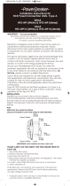
SIDE FRAMES
HEADER
SHROUD
CRATE 2
DOOR PANEL
CRATE 1
LOOSE PARTS BOX
Crates and Contents
GENERAL
INFORMATION
Because of variances in the construction of walls on
which the door will be mounted, fasteners are not
supplied. For proper anchoring of the door, we
recommend the use of thru-bolts. DO NOT remove
door sections from crate until you encounter the step in
which they are to be installed.
NOTE
Upon receipt of the shipment, check that you have received the correct number of pieces as shown (figure 1). Crate
will contain the side-covers, the header assembly, the loose parts box, and control box. For your protection, note
any damages or shortages on the carrier’s bill of lading before signing the bill for receipt.
The installation of this door will require at least a two man crew and a fork-li. Select a fork-li with liing height
based upon the height of the door, plus a minimum additional two feet.
Description Qty.
Installation Instructions 1
Warning Nameplate Assembly 2
Misc. Hardware -
Misc. Activation Devices -
Loose Parts
Figure 1: Crates and Contents
For installation of a 140 manual – single slide
door turn to page 8.
For installation of a 150 power – single slide door
turn to page 16.

ASI DOORS, INC. (800) 558-7068 asidoors.com
Door Measurements
MANUAL
INSTALLATION
WALL CLIPS
1. Measure door opening to verify door
dimensions(Figure 3). Based upon dimensions
in figure 3, determine that door will have
suicient wall space to open. Locate side
frames relative to the sides of the opening as
shown in figure 2.
Figure 2: Wall Clip Position
W.I.C
WALL
CLIP
WALL
CLIP
W.I.C. + 3/8"
3/16"
Figure 5: Mounting Header and Face FramesFigure 4: Checking Plumb and Square
Figure 3: Door Measurements
Width
(WIC x 2) + 10”
Height
(HIC)
Clearance for Sliding
WIC + 6 1/2”
Opening Width
(WIC)
4”
Height
(HIC + 11 1/2” max for STD Panel)
(HIC + 14 1/2” with Breakout Option)
4”

ASI DOORS, INC. (800) 558-7068 asidoors.com
Figure 6: installing wall clips and roller brackets (Bottom
roller brackets not present for leading edge on doors
with breakout egress option).
WALL CLIPS
ROLLER
BRACKETS
Frame and Header Assembly
Note recheck wall clips to be sure they are
plumb and level. Make any necessary
adjustments.
NOTE
2. Attach the le, righ or both bottom roller brackets
to the wall through the two holes in the bottom of
wall clip (Figure 6).
Figure 7: Fastening Face Frame Covers to Wall Clips
SCREW
TOP VIEW
(LEFT SIDE)
FACE
FRAME
WALL CLIP
SCREW
LOCATION
Note doors with the optional breakout egress
will not have a bottom roller bracket to secure
the leading edge of the panel when closed.
NOTE
1. Attach the wall clips to the wall flush with the
edge of the opeing, leaving the bottom 2 bolt
holes open for the floor hardware (Page 7, figure
2).
MANUAL
INSTALLATION
3. Attach the face frames with 2 screws per frame
(Figure 7).

ASI DOORS, INC. (800) 558-7068 asidoors.com
Header Installation
Caution improper installation of anchoring
devices, installation into aged or unsound
concrete or mounting to a non-plumb wall
without proper shimming; could result in
premature product wear or product failure.
Failure to properly install equipment could
result in property damage.
Warning when mounting rail, keep personnel
out of the area below the header until the rail
is secured to the wall. Failure to do so could
result in property damage, death or serious
injury.
4. For a right hand slide, position the le edge
of the header (w/o shrough) flush with the le
clip.
For a le hand slide, position the right edge
of the header (w/o shroud) flush with the right
edge of the wall clip.
5. Mount the header to the wall. Use the holes
provided in the header to mount it to the wall
(Page 12, Figure 9.)
Note we strongly recommend that thru-holes
be drilled for proper anchoring of the door to
the wall.
NOTE
Figure 8: Positioning the Header
W.I.C.
MANUAL
INSTALLATION

ASI DOORS, INC. (800) 558-7068 asidoors.com
Panel Installation and Adjustment
Figure 9: Attaching Panel to Header
SEAL EXTE
NSION FOR
BREAKOUT EGRESS
(OPTIONAL)
SEAL EXTENSION FOR
STANDARD PANEL
MOUNTING BOLTS
(BY OTHERS)
VERTICAL PANEL
ADJUSTMENT BOLT
HORIZONTAL PANEL
ADJUSTMENT BOLT
DOOR PANEL
GASKET
HEADER
END OF TRAVEL BUMPER
SHROUD
MOUNTING
BRACKET
1 Loosen the two horizontal panel adjusting bolts on top of each panel(s). These bolts will slide
between the two forks on the panel trolley bracket in the header (Figures 9 & 10B).
2 Measure the distance between the mounting bolts on the panel and manually position the panel
trolleys the same distance apart in the header.
3 Manually position the bottom of the panel over the guide roller. Then move the panel into position
so the two adjusting bolts are located on the forks of the panel trolleys.
4 Position the panel horizontally to provide a consistent seal and tighten the horizontal panel
adjusting bolts.
5 Back o the roller truck locking bolts on the panel trolleys and use the vertical panel adjustment
bolts to position the panel at the desired height. The panel gasket should have contact with the
floor for proper sealing. Tighten the locking bolts to secure the panel.
MANUAL
INSTALLATION

ASI DOORS, INC. (800) 558-7068 asidoors.com
Panel Installation and Adjustment Continued
NOTE minimal contact is all that is necessary to provide a tight seal. This will also extend the life of the
gasket.
NOTE
Figure 10A: Adjusting Jump Roller Clearnace
MANUAL
INSTALLATION
HORIZONTAL PANEL
ADJUSTMENT BOLTS
ROLLER TRUCK
LOCKING BOLTS VERTICAL PANEL
ADJUSTMENT BOLTS
SLIDE
PANEL
6. Adjust jump roller to have approx. .020” Gap
from underside of rail (figure 10a).
7. Manually operate the door and visually
inspect to ensure the gasket is making
contact around the perimeter of the
opening. Make any adjustments necessary to
maintain a seal.
8. Manually operate the door panels open and
closed. Verify that door panels move freely,
clear the opening, and contact bumpers at
the end of open and close travel.
9. If bumpers require adjustment, loosen
the socket head set screws on the bumper
bracket and slide the bumper into position
as needed. Lock the set screws down.
Figure 10B: Adjusting Bolt Locations

ASI DOORS, INC. (800) 558-7068 asidoors.com
Door Measurements
1. Measure door opening to verify door
dimensions (Figure 12). Based upon dimensions
in Figure 12, determine that door will have
suicient wall space to open. The side frames
will fit flush to the edge of the opening.
Figure 11: Wall Clip Position
W.I.C
WALL
CLIP
WALL
CLIP
W.I.C. + 3/8"
3/16"
POWER
INSTALLATION
WALL CLIPS
Figure 14: Mounting Header and Face Frames
Figure 13: Checking Plumb and Square
Figure 12: Door Measurements
Width
(WIC x 2) + 10”
Height
(HIC)
Clearance for Sliding
WIC + 6 1/2”
Opening Width
(WIC)
4”
Height
(HIC + 11 1/2” max for STD Panel)
(HIC + 14 1/2” with Breakout Option)
4”

ASI DOORS, INC. (800) 558-7068 asidoors.com
Frame and Header Assembly
POWER
INSTALLATION
Figure 15: installing wall clips and roller brackets (Bottom
roller brackets not present for leading edge on doors with
breakout egress option).
WALL CLIPS
ROLLER
BRACKETS
Note recheck wall clips to be sure they are
plumb and level. Make any necessary
adjustments.
NOTE
2. Attach the le, righ or both bottom roller brackets
to the wall through the two holes in the bottom of
wall clip (Figure 15).
Figure 16: Fastening Face Frame Covers to Wall Clips
SCREW
TOP VIEW
(LEFT SIDE)
FACE
FRAME
WALL CLIP
SCREW
LOCATION
Note doors with the optional breakout egress
will not have a bottom roller bracket to secure
the leading edge of the panel when closed.
NOTE
1. Attach the wall clips to the wall flush with the
edge of the opeing, leaving the bottom 2 bolt
holes open for the floor hardware (Page , Figure
11).
1. Locate photoeye cables on back of header and
identify each pair of wires by its location near
the grommeted holes in the bottom edge of the
header. You will be installing one set of an emitter
and receiver on each side frame. It must match
up with the corresponding emitter and receiver
on the other side frame. Remove the emitter and
receiver heads from each wire for installation into
face frames (Figure 16).

ASI DOORS, INC. (800) 558-7068 asidoors.com
Frame and Header Assembly Continued
POWER
INSTALLATION
Caution improper installation of anchoring
devices, installation into aged or unsound
concrete or mounting to a non-plumb wall
without proper shimming; could result in
premature product wear or product failure.
Failure to properly install equipment could
result in property damage.
Warning when mounting rail, keep personnel
out of the area below the header until the rail
is secured to the wall. Failure to do so could
result in property damage, death or serious
injury.
4. Position the photoeyes in the face frames in
pairs of emitter and receiver. The wires are
color-coded black or gray. Emitters are gray
and receivers are black. Match wire colors and
install the photoeyes as shown in Figure 18,
(Page 18), and Figure 24 (Page 22).
5. Use self-adhesive clamps and ties provided to
hold the wiring in place and contain any extra
length of wire.
6. For a right hand slide, position the le edge
of the header (w/o shroud) flush with the
le edge of the wall clip (Figure 17).
For a le hand slide, position the right edge
of the header (w/o shroud) flush with the
right edge of the wall clip.
Note we strongly recommend that thru-holes
be drilled for proper anchoring of the door to
the wall.
NOTE
Figure 17: Positioning the Header
W.I.C.

ASI DOORS, INC. (800) 558-7068 asidoors.com
Frame and Header Assembly Continued
Note we strongly recommend that thru-holes be
drilled for proper anchoring of the door to the
wall.
NOTE
POWER
INSTALLATION
7. Make sure the photoeye cables come
out of holes provided in the bottom of the
header and do not get cut or pinched during
positioning. Mount photoeye sensors as
shown in Figure 18. Pay attention to colors
of photoeye wires (Figure 18), and Figure 24
(Page 22).
8. Mount the header to the wall. Use the holes
provided in the header to mount it to the wall
(Page 19, Figure 19).
Caution improper installation of anchoring
devices, installation into aged or unsound
concrete or mounting to a non-plumb wall
without proper shimming; could result in
premature product wear or product failure.
Failure to properly install equipment could
result in property damage.
Note DO NOT plug into 115 VAC power at this
time.
NOTE
9. Connect the power cord to the 115VAC
grounded power inlet on the TCP-51
CONTROL UNIT (Page 23, Figure 25). Verify
that the voltage setting on the control unit is
set to 115VAC. Then route the cord through
the header and out to the power source.
10. Make sure the edges of all routing holes of
the power cord are smooth and have any
burrs removed. Use tie wraps or clips to
make sure power cord is secure inside the
header, and will not contact any moving
parts inside the header.
Figure 18: Connecting to Photoeyes
MOTOR &
BRAKE
FUSE
TRAFO SEC.
BATTERY ENCODER LOCK
MODULE
EPROM
TERMINAL
10+24V
OUT
OUT
OUT
OUT
OUT
IN
IN
IN
GND
+24V
open
exit
red
auto
o
p.lock
down
up
GND
shield
9
8
7
6
5
4
3
2
1
control panel
CONTROL UNIT
TCP-51LC
12
reversing photoeye 2
34P2
R
+–
T
–+
12
reversing photoeye 1
34P1
R
+–
T
–+
1
C
24 VDC
sensor outside emerg.
switch
key op.
switch
activators
sensor inside
24 VDC
GND
IN
GND
IN
+24V
GND
IN & RES
GND
E.PB
+24V
2345678910
J2
A B
battery module 50
motor rot. direction
jumper C9–C10 = clockwise (EB/ER)
no jumper = anticlockwise (EL)
A = with
B = without
J1
A B
automatic system configuration
A = yes (run system reset)
B = no
Art. KAU0005
BLUE
BLUE
GRAY
GRAY

ASI DOORS, INC. (800) 558-7068 asidoors.com
Panel Installation and Adjustment
POWER
INSTALLATION
1. Loosen the two horizontal panel adjusting bolts
on top of each panel(s). These bolts will slide
between the two forks on the panel trolley
bracket in the header (Figures 19B & 20).
2. Measure the distance between the mounting
bolts on the panel and manually position the
panel trolleys the same distance apart in the
header.
3. Manually position the bottom of the panel over
the guide roller. Then move the panel into
position so the two adjusting bolts are located
on the forks of the panel trolleys.
4. Position the panel horizontally to provide a
consistent seal and tighten the bolts.
5. Back o the locking bolts on the panel trolleys
and use the vertical panel adjustment bolts to
position the panel at the desired height. The
panel gasket should have contact with the floor
for proper sealing. Tighten the locking bolts to
secure the panel.
6. Adjust Jump Roller to have approximately 020”
gap from underside of rail (Figure 19A).
Figure 20: Attaching Panel to Header
Figure 19B: Adjusting Bolt Locations
HORIZONTAL PANEL
ADJUSTMENT BOLTS
ROLLER TRUCK
LOCKING BOLTS VERTICAL PANEL
ADJUSTMENT BOLTS
SLIDE
PANEL
SEAL EXTE
NSION FOR
BREAKOUT EGRESS
(OPTIONAL)
SEAL EXTENSION FOR
STANDARD PANEL
MOUNTING BOLTS
(BY OTHERS)
VERTICAL PANEL
ADJUSTMENT BOLT
HORIZONTAL PANEL
ADJUSTMENT BOLT
DOOR PANEL
GASKET
HEADER
END OF TRAVEL BUMPER
SHROUD
MOUNTING
BRACKET
Figure 19A : Adjusting Jump Roller Clearance

ASI DOORS, INC. (800) 558-7068 asidoors.com
Panel Installation and Adjustment Continued
POWER
INSTALLATION
7. Manually operate the door and visually inspect to ensure
the gasket is making contact around the perimeter of the
opening. Make any adjustments necessary to maintain a
seal.
1. Install warning label (Figure 21) to wall as
shown in Figure 22.
MOTOR &
BRAKE
FUSE
TRAFO SEC.
BATTERY ENCODER LOCK
MODULE
EPROM
TERMINAL
10+24V
OUT
OUT
OUT
OUT
OUT
IN
IN
IN
GND
+24V
open
exit
red
auto
o
p.lock
down
up
GND
shield
9
8
7
6
5
4
3
2
1
control panel
CONTROL UNIT
TCP-51LC
12
reversing photoeye 2
34P2
R
+–
T
–+
12
reversing photoeye 1
34P1
R
+–
T
–+
1
C
24 VDC
sensor outside emerg.
switch
key op.
switch
activators
sensor inside
24 VDC
GND
IN
GND
IN
+24V
GND
IN & RES
GND
E.PB
+24V
2345678910
J2
AB
battery module 50
motor rot. direction
jumper C9–C10 = clockwise (EB/ER)
no jumper = anticlockwise (EL)
A = with
B = without
J1
A B
automatic system configuration
A = yes (run system reset)
B = no
Art. KAU0005
WARNING
ASI TECHNOLOGIES INC.
17C024
This sliding door is designed for
vehicular and trained
pedestrian traic.
1.
Operation may be automatic.
Keep doorway clear at all
times.
2.
Door impact may cause
personal injury or property
damage.
3.
Failure to head these warnings
may result in equipment
and/or property damage
and/or perosnal or fatal injury.
4.
58"
LABEL
PUSH
PLATE
Figure 22: Warning Label Installation
Figure 21: Warning Label
Warning Label Installation
8. Manually operate the door panels open and closed.
Verify that door panels move freely, clear the opening,
and contact bumpers at the end of open and close
travel.
9. If bumpers require adjustment, loosen the socket head
set screws on the bumper bracket and slide the bumper
into position as needed. Lock the set screws down.
Note minimal contract is all that is necessary to
provide a tight seal. This will also extend the life of the gasket.
NOTE

ASI DOORS, INC. (800) 558-7068 asidoors.com
Electrical Controls
POWER
INSTALLATION
WARNING control box contains HIGH VOLTAGE! The following procedures should be
performed by qualified electrical personnel only. Wiring must meet all local, state, federal
and international, or other governing agency codes. Failure to do so could result in death or
serious injury.
The microprocessor control system is designed specifically for ASI Doors. The microprocessor programmed
self-diagnostic features convey both door status and troubleshooting indicators through individual letter
& number codes. Additional inputs are available for automatic door opening. Troubleshooting time is
significantly reduced since the letter & number codes direct you to specific problems. Initial electrical
hookup is made easy with conveniently located plug-in type 115 VAC power connectors (shipped in loose
parts box).
INPUT POWER
The nominal supply voltage for the control panel is 115 VAC. Be sure to verify this voltage supply is
available. The control unit provides 24 VDC for other sensing and electrical devices.
Figure 27: 2301/2401 Operator

ASI DOORS, INC. (800) 558-7068 asidoors.com
Electrical Controls Continued
POWER
INSTALLATION
Electrical Schematic drawing # 18D248
Note Standard schematic show. Refer to drawing shipped with
your specific door.
NOTE
Figure 24: Operator Wiring Schematic

ASI DOORS, INC. (800) 558-7068 asidoors.com
Electrical Controls Continued
POWER
INSTALLATION
WARNING control box contains HIGH VOLTAGE! The following procedures should be
performed by qualifiedelectrical personnel only. Wiring must meet all local, state, federal
and international, or other governing agency codes. Failure to do so could result in death or
serious injury.
MAIN POWER CONNECTION: The door is supplied with a grounded power cord connector.
1. Check that all edges of feed-through holes for the power cable are smooth and have no burrs.
WARNING Disconnect power at the fused disconnect during all electrical or mechanical
service. Disconnect must be properly locked out during maintenance or service of equipment.
Failure to disconnect power could result in death or serious injury.
2. Check the correct setting of the voltage selector (Figure 25).
Note power cable NOT supplied by ASI.
NOTE
Figure 25: Power Input Connection
/