5
IMPORTANT SAFETY INSTRUCTIONS
ENTRAPMENT ALARM (UL 325; 30A.1.1A)
The GTO® Gate Opener is designed to stop and reverse within 2 seconds when the gate comes in contact with
an obstruction. Additionally, these openers are equipped with an audio entrapment alarm which will activate
if the unit obstructs twice while opening or closing. This alarm will sound for a period of 5 minutes, or until
the opener receives an intended signal from a hard wired entry/exit source (e.g. push button control or keypad)
and the gate returns to a fully open or fully closed position. Turning the power switch on the control box OFF
and back ON will also deactivate the alarm. Wireless controls such as transmitters and wireless keypads will not
deactivate the alarm.
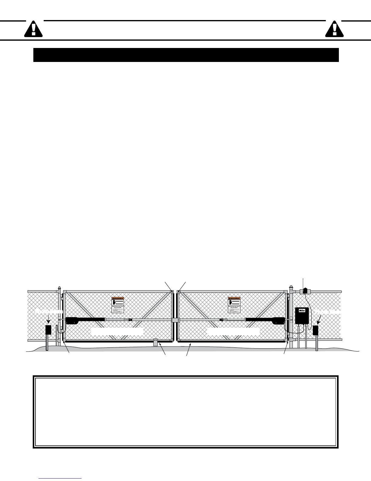
Bottom Edge Contact Sensor
on both sides of the
ge Contact Sensor
on both sides of the gate
Post Edge Contact Sensor
on both sides of the
ate
Post Edge Contact Sensor
on both sides of the
ate
Vehicular Gate Vehicular Gate
500
UL325 SERIES
®
E-Z GATE OPENER
1-800-543-GATE (4283)
www.mightymule.com
Photo BeamPhoto Beam Photo BeamPhoto Beam
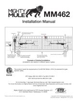
Secondary Means of Protection Against Entrapment
As specified by Gate Operator Safety Standard, UL 325 (30A.1.1), automatic gate operators shall have an inherent entrapment
sensing system, and shall have provisions for, or be supplied with, at least one independent secondary means to protect
against entrapment. GTO gate openers utilizes Type A, an inherent (i.e., built-in) entrapment sensing system as the primary
type of entrapment protection. Also, the gate opener has provisions for the connection of Type B1 or B2 protection to be
used as the secondary type of entrapment protection, if desired.
1. For gate operators utilizing a non-contact sensor (e.g., photo-electric sensor– Type B1) in accordance with UL 325
(51.8.4 [h]):
A. Refer to the sensor manufacturer’s instructions on the placement of non-contact sensors for each type of application.
B. Care shall be exercised to reduce the risk of nuisance tripping, such as when a vehicle trips the sensor while the gate
is still moving.
C. One or more non-contact sensors shall be located where the risk of entrapment or obstruction exists, such as the
perimeter reachable by a moving gate or barrier.
2.
For gate operators utilizing a contact sensor (e.g., safety edge sensor– Type B2) in accordance with UL 325 (51.8.4 [i]):
A. One or more contact sensors shall be located at the leading edge, bottom edge, and post edge, both inside and outside
of a vehicular swing gate system.
B. A hard wired contact sensor shall be located and its wiring arranged so that the communication between the sensor
and the gate operator is not subjected to mechanical damage.
C. A wireless contact sensor such as one that transmits radio frequency (RF) signals to the gate operator for entrapment
protection functions shall be located where the transmission of the signals are not obstructed or impeded by building
structures, natural landscaping or similar obstruction. A wireless contact sensor shall function under the intended
end-use conditions.
You may want to consider adding photo beams to your installation. GTO Photo Beams [R4222] provide a “non contact”
means of entrapment protection.