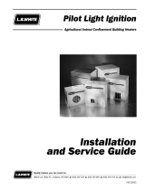
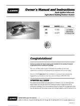
L.B. White Jet 200 Owner's Manual And Instructions
- Type
- Owner's Manual And Instructions

L.P. Gas Vapor
Withdrawal
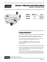
Congratulations!
You have purchased the finest circulating construction heater available.
Your new L.B. White heater incorporates the benefits from the most experienced
manufacturer of heating products using state-of-the-art technology.
We, at L.B. White, thank you for your confidence in our products and
welcome any suggestions or comments you may have...call us, toll-free,
at 1-800-345-7200.
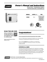
Owner's Manual and Instructions
Jet 200 and Twin Jet 400 Circulating Construction Heaters
ATTENTION ALL USERS
This heater has been tested and evaluated by L.B. White Co., Inc as a direct fired
circulating construction heater with intended use for primarily the temporary heating
of buildings under construction, alteration, or repair. If you are considering using this
product for any applications other than its intended use, then please contact your
fuel gas supplier or the L.B. White Co., Inc.
150-22178
MODELS OUTPUT (Btuh) FUEL
324 200,000
326 200,000
328 400,000
330 400,000

WARNING
Fire and Explosion Hazard
■Not for home or recreational vehicle use.
■Installation of this heater in a home or
recreational vehicle may result in a fire or
explosion.
■Fire or explosions can cause property
FOR YOUR SAFETY
If you smell gas:
1. Open windows.
2. Don't touch electrical switches.
3. Extinguish any open flame.
4. Immediately call your gas supplier.
FOR YOUR SAFETY
Do not store or use gasoline or other
flammable vapors and liquids in the vicinity of
this or any other appliance.
WARNING
Fire and Explosion Hazard
■Keep solid combustibles a safe distance
away from the heater.
■Solid combustibles include wood or paper
products, building materials and dust.
■Do not use the heater in spaces which
contain or may contain volatile or airborne
combustibles.
■Volatile or airborne combustibles include
gasoline, solvents, paint thinner, dust
particles or unknown chemicals.
■Failure to follow these instructions may
result in a fire or explosion.
■Fire or explosions can lead to property
damage, personal injury or loss of life.
GENERAL HAZARD WARNING
■Failure to comply with the precautions and instructions provided with this heater, can result in:
— Death
— Serious bodily injury or burns
— Property damage or loss from fire or explosion
— Asphyxiation due to lack of adequate air supply or carbon monoxide poisoning
— Electrical shock
■Read this Owner’s Manual before installing or using this product.
■Only properly-trained service people should repair or install this heater.
■Save this Owner’s Manual for future use and reference.
■Owner’s Manuals and replacement labels are available at no charge. For assistance, contact
L.B. White at 800-345-7200.
WARNING
■Proper gas supply pressure must be provided to the inlet of the heater.
■Refer to data plate for proper gas supply pressure.
■Gas pressure in excess of the maximum inlet pressure specified at the heater inlet can cause
fires or explosions.
■Fires or explosions can lead to serious injury, death, or building damage.
■Gas pressure below the minimum inlet pressure specified at the heater inlet may cause
improper combustion.
■Improper combustion can lead to asphyxiation or carbon monoxide poisoning and therefore
serious injury or death.
2

This Owner's Manual includes all options and accessories
commonly used on this heater. However, depending on the
configuration purchased, some options and accessories
may not be included.
When calling for technical service assistance, or for other
specific information, always have model number,
configuration number and serial number available. This
information is contained on the dataplate. The dataplate is
located on the motor housing of the heater.
This manual will instruct you in the operation and care of
your unit. Have your qualified installer review this manual
with you so that you fully understand the heater and how it
functions.
The gas supply line installation, installation of the heater,
and repair and servicing of the heater requires continuing
expert training and knowledge of gas heaters and should
not be attempted by anyone who is not so qualified. See
page 6 for definition of the necessary qualifications.
Contact your local L.B. White distributor or the L.B. White
Co., Inc. for assistance, or if you have any questions about
the use of the equipment or its application.
The L.B. White Co., Inc. has a policy of continuous product
improvement. It reserves the right to change specifications
and design without notice.
SECTION PAGE
General Information . . . . . . . . . . . . . . . . . . . . . . . . . . . . . . . . . . . . . . . . . . . . . . . . . . . . . . . . . . . . . . . . . . .3
Heater Specifications . . . . . . . . . . . . . . . . . . . . . . . . . . . . . . . . . . . . . . . . . . . . . . . . . . . . . . . . . . . . . . . . . .4
Safety Precautions . . . . . . . . . . . . . . . . . . . . . . . . . . . . . . . . . . . . . . . . . . . . . . . . . . . . . . . . . . . . . . . . . . . .5
Installation Instructions
General . . . . . . . . . . . . . . . . . . . . . . . . . . . . . . . . . . . . . . . . . . . . . . . . . . . . . . . . . . . . . . . . . . . . . . . . .7
Burner and Gas Control Assembly (Models 324 & 328) . . . . . . . . . . . . . . . . . . . . . . . . . . . . . . . . . .8
Duct Installation (Models 324 & 326) . . . . . . . . . . . . . . . . . . . . . . . . . . . . . . . . . . . . . . . . . . . . . . . .10
Thermostat Installation . . . . . . . . . . . . . . . . . . . . . . . . . . . . . . . . . . . . . . . . . . . . . . . . . . . . . . . . . . .10
Hose and Regulator Assembly . . . . . . . . . . . . . . . . . . . . . . . . . . . . . . . . . . . . . . . . . . . . . . . . . . . . . .10
Start-Up Instructions . . . . . . . . . . . . . . . . . . . . . . . . . . . . . . . . . . . . . . . . . . . . . . . . . . . . . . . . . . . . . . . . .11
Shut-Down Instructions . . . . . . . . . . . . . . . . . . . . . . . . . . . . . . . . . . . . . . . . . . . . . . . . . . . . . . . . . . . . . . .11
Cleaning Instructions . . . . . . . . . . . . . . . . . . . . . . . . . . . . . . . . . . . . . . . . . . . . . . . . . . . . . . . . . . . . . . . . .12
Maintenance Instructions . . . . . . . . . . . . . . . . . . . . . . . . . . . . . . . . . . . . . . . . . . . . . . . . . . . . . . . . . . . . .12
Service Instructions . . . . . . . . . . . . . . . . . . . . . . . . . . . . . . . . . . . . . . . . . . . . . . . . . . . . . . . . . . . . . . . . . .12
Checking Gas Pressure . . . . . . . . . . . . . . . . . . . . . . . . . . . . . . . . . . . . . . . . . . . . . . . . . . . . . . . . . . . . . . .13
Electrical Connection and Ladder Diagram (Models 326 & 330) . . . . . . . . . . . . . . . . . . . . . . . . . . . . .14
Troubleshooting Information . . . . . . . . . . . . . . . . . . . . . . . . . . . . . . . . . . . . . . . . . . . . . . . . . . . . . . . . . . .15
Heater Component Function . . . . . . . . . . . . . . . . . . . . . . . . . . . . . . . . . . . . . . . . . . . . . . . . . . . . . . . . . . .17
Parts Identification
Parts Schematic . . . . . . . . . . . . . . . . . . . . . . . . . . . . . . . . . . . . . . . . . . . . . . . . . . . . . . . . . . . . . . . . .18
Parts List . . . . . . . . . . . . . . . . . . . . . . . . . . . . . . . . . . . . . . . . . . . . . . . . . . . . . . . . . . . . . . . . . . . . . . .19
Warranty Policy . . . . . . . . . . . . . . . . . . . . . . . . . . . . . . . . . . . . . . . . . . . . . . . . . . . . . . . . . . . . . . . . . . . . .20
Replacement Parts and Service . . . . . . . . . . . . . . . . . . . . . . . . . . . . . . . . . . . . . . . . . . . . . . . . . . . . . . . .20
Table of Contents
General Information
3

SPECIFICATIONS
Maximum Input (BTUH) 200,000 400,000
450 CFM 900 CFM
45 x 16 x 26 58 x 22 x 29
TOP 6 ft.
SIDES 5 ft.
BACK 5 ft.
BLOWER
OUTLET
GAS
SUPPLY
65 66 160 165
72 91 170 175
324 326 328 330
w/ Thermostatic Panel w/ Thermostatic Panel
L.P. L.P.
MMooddeell
Ventilation Air Required
to Support Combustion
Net Weight (lbs.)
Shipping Weight (lbs.)
Electrical Supply
(Volts/Hz/Phase)
Amp Draw
Dimensions (Inches)
L x W x H
Minimum Safe
Distances From
Nearest
Combustible
Materials
STARTING
CONTINUOUS
OPERATION
Motor Characteristics
Fuel Consumption Per Hour
Inlet Gas Supply
Pressure Acceptable
at the Inlet of the
Pilot Safety Control
Valve
MAX.
MIN.
24 PSIG.
Sleeve Bearing
6 ft.
115/60/1
4
Heater Specifications
L.P. Gas Supply - 6 ft.
12.0
4.0
1/4 H.P.
1725 RPM
24 PSIG.
9.3 lbs. 18.5 lbs.
Fuel Type

LP ggas aand nnatural ggas hhave mman-mmade oodorants aadded sspecifically ffor ddetection oof ffuel ggas lleaks.
If aa ggas lleak ooccurs, yyou sshould bbe aable tto ssmell tthe ffuel ggas.
THAT’S YYOUR SSIGNAL TTO GGO IINTO IIMMEDIATE AACTION!
■Do not take any action that could ignite the fuel gas. Do
not operate any electrical switches. Do not pull any
power supply or extension cords. Do not light matches
or any other source of flame. Do not use your
telephone.
■Get everyone out of the building and away from the area
immediately.
■Close all propane (LP) gas tank or cylinder fuel supply
valves, or the main fuel supply valve located at the
meter if you use natural gas.
■Propane (LP) gas is heavier than air and may settle in
low areas. When you have reason to suspect a propane
leak, keep out of all low areas.
■Use your neighbor’s phone and call your fuel gas
supplier and your fire department. Do not re-enter the
building or area.
■Stay out of the building and away from the area until
declared safe by the firefighters and your fuel gas
supplier.
■FINALLY, let the fuel gas service person and the
firefighters check for escaped gas. Have them air out
the building and area before you return. Properly
trained service people must repair the leak, check for
further leakages, and then relight the appliance for you.
■Some ppeople ccannot ssmell wwell. SSome ppeople ccannot
smell tthe oodor oof tthe mman-mmade cchemical aadded tto
propane ((LP) oor nnatural ggas. YYou mmust ddetermine iif yyou
can ssmell tthe oodorant iin tthese ffuel ggases.
■Learn to recognize the odor of propane (LP) gas and
natural gas. Local propane (LP) gas dealers will be
more than happy to give you a scratch and sniff
pamphlet. Use it to become familiar with the fuel gas
odor.
■Smoking can decrease your ability to smell. Being
around an odor for a period of time can affect your
sensitivity to that particular odor. Odors present in
animal confinement buildings can mask fuel gas odor.
■The oodorant iin ppropane ((LP) ggas aand nnatural ggas iis
colorless aand tthe iintensity oof iits oodor ccan ffade uunder
some ccircumstances.
■If there is an underground leak, the movement of gas
through the soil can filter the odorant.
■Propane (LP) gas odor may differ in intensity at different
levels. Since propane (LP) gas is heavier than air, there
may be more odor at lower levels.
■Always bbe ssensitive tto tthe sslightest ggas oodor. If you
continue to detect any gas odor, no matter how small,
treat it as a serious leak. Immediately go into action as
discussed previously.
5
Safety Precautions
FUEL GAS ODOR
ODOR FADING -- NO ODOR DETECTED
ATTENTION -- CRITICAL POINTS TO REMEMBER!
■Propane (LP) gas has a distinctive odor. Learn to
recognize these odors. (Reference Fuel Gas Odor and
Odor Fading sections above.
■
If you have not been properly trained in repair and service
of propane (LP) gas then do not attempt to light heater,
perform service or repairs, or make any adjustments to
the heater on the propane (LP) gas fuel system.
■Even if you are not properly trained in the service and
repair of the heater, ALWAYS be consciously aware of
the odors of propane (LP) gas and natural gas.
■A periodic sniff test around the heater or at the
heater’s joints; i.e. hose, connections, etc., is a good
safety practice under any conditions. If you smell even
a small amount of gas, CONTACT YOUR FUEL GAS
SUPPLIER IMMEDIATELY. DO NOT WAIT!
WARNING
■Do not use this heater for heating human living
quarters.
■Do not use in unventilated areas.
■The flow of combustion and ventilation air must not be
obstructed.
■Proper ventilation air must be provided to support the
combustion air requirements of the heater being used.
■Refer to the specification section of the heater’s
Owner’s Manual, heater dataplate, or contact the L.B.
White Company to determine combustion air ventilation
requirements of the heater.
■Lack of proper ventilation air will lead to improper
combustion.
■Improper combustion can lead to carbon monoxide
poisoning leading to serious injury or death. Symptoms
of carbon monoxide poisoning can include headaches,
dizziness and difficulty in breathing.
Asphyxiation HHazard

1. Do not attempt to install, repair, or service this heater
or the gas supply line unless you have continuing
expert training and knowledge of gas heaters.
Qualifications for service and installation of this
equipment are as follows:
a.
To be a qualified gas heater service person, you
must have sufficient training and experience to
handle all aspects of gas-fired heater installation,
service and repair. This includes the task of
installation, troubleshooting, replacement of
defective parts and testing of the heater. You
must be able to place the heater into a continuing
safe and normal operating condition. You must
completely familiarize yourself with each model
heater by reading and complying with the safety
instructions, labels, Owner’s Manual, etc., that is
provided with each heater.
b.
To be a qualified gas installation person, you must
have sufficient training and experience to handle
all aspects of installing, repairing and altering gas
lines, including selecting and installing the proper
equipment, and selecting proper pipe and tank
size to be used. This must be done in accordance
with all local, state and national codes as well as
the manufacturer’s requirements.
2. All installations and applications of L.B. White heaters
must meet all relevant local, state and national
codes. Included are L.P. gas, natural gas, electrical,
and safety codes. Your local fuel gas supplier, a local
licensed electrician, the local fire department or
similar government agencies, or your insurance agent
can help you determine code requirements.
-- ANSI/NFPA 58, latest edition, Standard for
Storage and Handling of Liquefied Petroleum
Gas and/or
-- ANSI Z223.1/NFPA 54, National Fuel Gas
Code
-- ANSI/NFPA 70, National Electrical Code.
3. We cannot anticipate every use which maybe made of
our heaters. Check with the local fire safety authority
if you have questions about applications.
4. Forced air heaters shall not be directed toward any LP
gas container within 20 feet (6.10 meters). Do not
wash the heater. Use only compressed air, a soft
brush or dry cloth to clean the interior of the heater
and it’s components.
5. The heater shall be installed so that it is not directly
exposed to water spray, rain, or dripping water.
6. Do not locate fuel gas containers or fuel supply
hoses anywhere near the blower outlet of the heater.
7. Do not block air intakes or discharge outlets of the
heater. Doing so may cause improper combustion or
damage to heater components leading to property
damage.
8. The hose assembly shall be visually inspected on a
daily basis after heater relocation and when the
heater is in use. If it is evident there is excessive
abrasion or wear, or if the hose is cut, it must be
replaced prior to the heater being put into operation.
The hose assembly shall be protected from building
materials, and contact with hot surfaces during use.
The hose assembly shall be that specified by the
manufacturer. See parts list.
9. Check for gas leaks and proper function upon heater
installation, when relocating, and after servicing.
Refer to leak check instructions within installation
section of this manual.
10. This heater should be inspected for proper operation
by a qualified service person before each use and at
least annually.
11. Always turn off the gas supply to the heater if the
heater is not going to be used in the heating of the
work space.
12. This heater is equipped with a three-prong
(grounding) plug for your protection against shock
hazard and must be plugged directly into a properly
grounded three-prong receptacle. Failure to use a
properly grounded receptacle can result in electrical
shock, personal injury, or death.
13. If gas flow is interrupted and flame goes out, do not
relight the heater until you are that all gas that may
have accummulated has cleared away. In any event,
do not relight the heater for at least 5 minutes.
14. Minimum LP gas supply cylinder size to be used shall
be 100 pounds when using a cylinder supply system.
The system must be arranged to provide vapor
withdrawal from the operating cylinder.
15. When the heater is to be stored indoors, the
connection between the L.P. gas supply cylinder(s)
and the heater must be disconnected and the
cylinder(s) removed form the heater and stored in
accordance with Chapter 5 if the Standard for the
Storage and Handling of Liquified Petroleum Gases,
ANSI/NFPA 58.
16. L.P. gas supply containers have left handed threads.
Always use the appropriate wrench to make a
connection to tighten or loosen the P.O.L. fitting at the
cylinders’ gas supply valve.
6
WARNING
Fire HHazard
■Temperatures at base of Model 328 and 330 heaters
may ignite combustible materials
■Use on non-combustible materials to avoid a fire
hazard.
ATTENTION
■Model 328 & 330 heaters are not suitable for use on
any wooden floors (plywood, particle board, pressboard,
etc.) and shall not be set up on these nor any other
combustible materials.
■If the heater is used on a combustible floor the heater
shall rest on a suitable heat insulating material such as
concrete of at least 1 inch thickness or equivalent. The
insulating material shall extend beyond the heater 2
feet or more in all directions.

1. Read all safety precautions and follow L. B. White
recommendations when installing this heater. If
during the installation or relocating of heater, you
suspect that a part is damaged or defective, call a
qualified service agency for repair or replacement.
2. Make sure the heater is properly installed before use.
Observe and obey all minimum safe distances of the
heater to the nearest combustible materials. Safe
distances are given on the heater dataplate and on
page 4 of this manual.
3. The heater is approved for indoor use only.
4. The heater shall not be used with ductwork.
5. The heater’s gas pressure regulator (with pressure
relief valve) must be protected from adverse weather
conditions (rain, ice, snow) as well as from building
materials (tar, concrete, plaster, etc.) which can affect
safe operation and could result in property damage or
injury.
6. Heaters used in the vicinity of combustible tarpaulins,
canvas, plastics, wind barriers, or similar coverings
shall be located at least 10 feet from the coverings.
The coverings shall be securely fastened to prevent
ignition or upsetting of the heater due to wind action
on the covering or other material.
7. Check all connections for gas leaks using approved
gas leak detectors. Gas leak testing is performed as
follows:
-- Check all pipe connections, hose connections,
fittings and adapters upstream of the gas
control with approved gas leak detectors.
-- In the event a gas leak is detected, check the
components involved for cleanliness and
proper application of pipe compound before
further tightening.
-- Furthermore tighten the gas connections as
necessary to stop the leak.
-- After all connections are checked and any
leaks are stopped, turn on the main burner.
-- Stand clear while the main burner ignites to
prevent injury caused from hidden leaks that
could cause flashback.
-- With the main burner in operation, check all
connections, hose connections, fittings and
joints as well as the gas control valve inlet and
outlet connections with approved gas leak
detectors.
-- If a leak is detected, check the components
involved for cleanliness in the thread areas
and proper application of pipe compound
before further tightening.
-- Tighten the gas connection as necessary to
stop the leak.
-- If necessary, replace the parts or components
involved if the leak cannot be stopped.
-- Ensure all gas leaks have been identified and
repaired before proceeding.
WARNING
Fire aand EExplosion HHazard
CCaann ccaauussee pprrooppeerrttyy ddaammaaggee,, sseevveerree iinnjjuurryy oorr ddeeaatthh
1. To avoid dangerous accumulation of fuel gas, turn
off gas supply at the heater service valve before
starting installation, and perform gas leak test after
completion of installation.
2. Do not force the gas control pilot button. Use only
your hand to depress the pilot button. Never use
any tools. If the button will not operate by normal
hand pressure the control should be replaced by a
qualified service technician. Force or attempted
repair may result in fire or explosion.
7
Installation Instructions
GENERAL
WARNING
Fire aand EExplosion HHazard
■Do not use open flame (matches, torches, candles,
etc.) in checking for gas leaks.
■Use only approved leak detectors.
■Failure to follow this warning can lead to fires or
explosions.
■Fires or explosions can lead to property damage,
personal injury or loss of life.

8. A qualified service agency must check for proper
operating gas pressure upon installation of the
heater.
9. Light according to instructions on heater or within
owner's manual.
10. Make sure the heater has the proper gas regulator for
the application. A regulator must be connected to the
gas supply so that gas pressure at the inlet to the gas
valve is regulated within the range specified on the
dataplate at all times. Contact your gas supplier, or
the L.B. White Co., Inc. if you have any questions.
11. This heater is configured for use for L.P. gas vapor
withdrawal only. Do not use the heater in an L.P. gas
liquid withdrawal system or application. If you are in
doubt, contact the L.B. White Co., Inc.
12. Eventually, like all electrical/mechanical devices, the
thermostat can fail. For heaters so equipped,
thermostat failure may result in an underheating
condition which may allow or cause damage to
construction materials, such as cement or drywall.
The thermostat should be tested to make sure it turns
the heater on and off within a temperature
differential of ±3°F.
13. Take time to understand how to operate and maintain
the heater by using this Owner’s Manual. Make sure
you know how to shut off the gas supply to the
building and also to the individual heater. Contact
your fuel gas supplier if you have any questions.
14. Any defects found in performing any of the service or
maintenance procedures must be eliminated and
defective parts replaced immediately. The heater
must be retested by properly qualified service
personnel before placing the heater back into use.
8
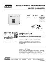
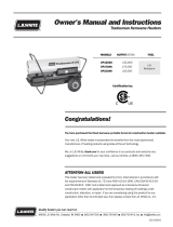
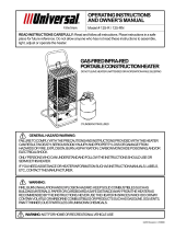
BURNER AND GAS CONTROL ASSEMBLY
BURNER
PILOT BRACKET
SCREWS
ATTACHMENT NUT
THERMOCOUPLE
THERMOCOUPLE HOLDER
ATTENTION
■Assembly of burner and gas control components
is required on Model 324 and 328 heaters. Refer
to following instructions and illustrations.
■Model 326 and 330 heaters ship with gas control
components factory installed.
PILOT BURNER HEAD
PILOT ORIFICE
1. Attach pilot bracket to burner casting with machine
screws. Tighten the screws securely See Fig. 1.
FIG. 1
2. Align the threaded hole in the pilot burner head to
hole in the pilot bracket. Thread pilot orifice into pilot
head until hex of orifice butts up against pilot
bracket. See Fig. 2.
FIG. 2
3. Position the thermocouple within its holder on the
pilot bracket. Secure in place with its attachment
nut. Tighten the nut securely. See Fig. 3.
FIG. 3
4. Slide compression nut and sleeve onto the pilot tube.
Form the small screen around this end of the pilot
tube to prevent debris from entering the pilot orifice.
See Fig. 4.

9
THERMOCOUPLE TO SAFETY
CONTROL VALVE PILOT TUBE TO 90o ELL
BURNER MOUNTING
BRACKET
MOUNTING HOLE
IN BURNER
TAB
SCREEN
SLEEVE
NUT
JAM NUT
HEX ON
BURNER ORIFICE
TIP OF BURNER ORIFICE
IS FLUSH WITH INSIDE
OF BURNER
JAM NUT
BURNER MOUNTING
BRACKET
JAM NUT TIGHTENED
AGAINST BURNER
MOUNTING BRACKET
FIG. 4
5. Thread compression nut onto pilot orifice. Ensure
that compression sleeve and pilot tube are firmly
pushed up within pilot orifice. Tighten the nut
securely. See Fig. 5
FIG. 5
6. Thread jam nut onto burner orifice so it butts up
against hex at end of orifice threads. See Fig. 6
FIG. 6
7. Position the burner casting within the burner
mounting bracket. The tab on the burner bracket
must fit within the small hole of the burner casting.
See Fig. 7.
FIG. 7
8. Thread the orifice with control assembly into the
inlet of the burner casting so that the tip of the
burner orifice is flush with the inside of the burner
and so the control assembly is positioned as
shown. See Fig. 8.
FIG. 8
9. Tighten the jam nut up against the burner mounting
bracket. See Fig. 9.
FIG. 9
10. Carefully hand form the thermocouple and pilot line
through the hole in the burner mounting bracket to
align with safety control valve. See Fig. 10.
11. Thread the thermocouple connector nut into the
pilot safety control valve. Tighten finger tight and
snug into place with the appropriate wrench. See
Fig. 10.
12. Slide the remaining compression nut and sleeve
onto the other end of the pilot line tube. Thread the
compression nut onto the 90 degree elbow at the
safety control valve while firmly pushing the pilot
tube into the elbow. Tighten the compression nut
securely. See Fig. 10.
FIG. 10

A thermostatic control panel kit with solenoid is
available for field installation. The kit is part number
500-00015. Installation instructions are provided
with the kit.
WARNING
Electrical SShock HHazard
■Disconnect the electrical supply before connecting the
thermostat to the heater.
■Failure to follow this warning can result in electrical
shock, leading to personal injury or death.
10
THERMOSTAT INSTALLATION
Models 324 & 328
HOSE AND REGULATOR ASSEMBLY
1. Always use approved pipe thread compound suitable
for use with L.P. gas or natural gas on the threaded
connections.
2. Assemble the components together according to the
figure. This view is to show general assembly of the
components only.
3. Tighten all connections securely.
4. Check aall cconnections ffor ggas lleaks uusing aapproved
gas lleak ddetectors.
FIG. 12
ATTENTION
■Duct installation is required for Models 324 and 326.
Refer to the following instructions and illustrations.
■Model 328 and 330 heaters will have the duct factory
installed.
1. Fasten crimped end of duct to collar end of heater
opposite burner. Use screw provided.
1. Fasten other end to fan housing inlet with
screwprovided.
COLLAR
SCREW
CRIMPED END
FAN HOUSING
INLET
SCREW
FIG. 11
DUCT INSTALLATION
HOSE
REGULATOR
L.P. GAS SUPPLY CONTAINER VALVE
TO HEATER

1. Slowly open the LP Gas supply container valve.
2. Fully depress the button on the pilot safety control
valve while applying flame to the pilot.
FIG. 13
3. Keep the pilot button depressed for about 30
seconds to allow the thermocouple to warm up so the
pilot stays lit after the pilot button is released.
4. Connect the heater’s power cord to an approved
electrical supply.
5. To ignite the main burner:
Models 324 and 328
- Fully open the manual main burner valve located
between the pilot safety control and burner.
- The main burner will light.
Models 326 and 330
- Fully open the manual main burner valve located
between electrical solenoid valve and burner.
- Set the thermostat on the control panel to a point
above room temperature
- The main burner will light.
1. Close the gas supply valve located on the LP gas
supply container.
2. Allow the heater to burn off any fuel gas remaining in
the gas supply line.
3. Close the manual main burner valve on the heater.
4. For heaters so equipped, set the thermostat to “Off”
or “No Heat”.
5. Disconnect the heater from its gas and electrical
supplies.
11
Start-Up Instructions
Shut-Down Instructions
WARNING
Burn HHazard
■Close the manual main burner valve before lighting the
pilot.
■Failure to do so will result in the main burner igniting
when the pilot is being lit.
■Serious injury or death by burns may occur.
ATTENTION
■On new installations it may take a short time for gas to
purge out any air in the pilot line before the pilot stays
lit.
MANUAL MAIN
BURNER VALVE
PILOT
BUTTON

12
1. The area surrounding the heater shall be kept clear
and free from combustible materials, gasoline, and
other flammable vapors and liquids.
2. Have your gas supplier check all gas piping annually
for leaks or restrictions in gas lines.
3. Regulators must be periodically inspected to make
sure the regulator vents are not blocked. Debris,
insects, insect nests, snow, or ice on a regulator can
block vents and cause excess pressure at the
appliance.
4. Regulators can wear out and function improperly.
Have your gas supplier check the date codes on all
regulators installed and check delivery pressures to
the appliance to make sure that the regulator is
reliable.
5. Check all wiring associated terminals and electrical
components within the heater for corrosion, frayed or
cut insulation, tight connections, etc. Repair or
replace as necessary.
6. Review all heater markings (i.e. wiring diagram,
warnings, start-up, shut-down, troubleshooting, etc.)
at the time of maintenance for legibility. Make sure
none are cut, torn, or otherwise damaged. Any
damaged markings must be replaced immediately by
contacting the L.B. White Co., Inc. Dataplates, start-
up and shut-down instructions and warnings are
available at no cost. A nominal charge will be applied
for wiring diagrams.
1. Before cleaning, shut off all gas supply valves and
disconnect electrical supply.
2. The heater should have dirt or dust removed
periodically:
a. Before each use give the heater a general
cleaning using compressed air or a soft brush or
dry rag on its case and internal components. At
this time, dust off the motor case to prevent
the
motor from over-heating.
b. At least once a year, give the heater a thorough
cleaning. At this time, remove the fan and motor
assembly and brush or blow off the fan blade
assembly. Additionally, make sure the burner air
inlet venturi ports and the casting are free of dust
accumulation.
WARNING
Do not use a pressure washer, water, or liquid cleaning
solution on any gas controls. Use of a pressure washer,
water, or liquid cleaning solution on the control
components can cause severe personal injury or
property damage due to water and/or liquids:
* In electrical components, and wires causing
electrical shock or equipment failure.
* On gas control valves causing corrosion which
can result in gas leaks and fire or explosion from the
leak.
Clean all components of the heater with pressurized air, a
dry brush or a dry cloth.
Cleaning Instructions
Maintenance Instructions
WARNING
Fire, BBurn, aand EExplosion HHazard
■This heater contains electrical and mechanical components in the gas management, and safety systems.
■Such components may become inoperative or fail due to dust, dirt, wear and aging.
■Periodic cleaning and inspection as well as proper maintenance are essential to avoid serious injury or property
damage.
Service Instructions
The servicing of components such as burner orifice, pilot
orifice, thermocouple, and pilot tubing may be accomplished
by referring to the Burner and Gas Control Assembly
Instructions provided within this manual. The assembly
procedures may be reversed for disassembly and servicing
of burner related components. These basic instructions
pertain to all heaters represented in this manual.
ATTENTION
When performing any service work, it is necessary to adhere
to the following guidelines:
■Always close the fuel supply valves to the heater.
■Allow the heater to cool before servicing.
■Leak check all gas connections after performing service
work. Use approved leak detectors.

ATTENTION
This procedure is to be done once a year prior to the heating
season. Anytime the heater is moved from one job location
to the next, or after servicing the heater.
MATERIALS REQUIRED
(To be secured through local purchase)
Quantity Description
1 High Pressure Gas Gauge capable of
reading up to 35 PSIG
1 1/4 in. Tee
1 1/4 in. Nipple
A. PREPARATION
1. Close fuel supply valve at LP gas supply container.
2. Allow heater to burn off gas remaining in it’s gas
supply line..
3. Close manual main burner valve on heater.
4. Remove gas hose from heater.
5. Remove hose adapter from inlet of pilot safety control
valve.
B. GAUGE INSTALLATION
1. Connect the following materials together in the order
as given. See Fig. 14.
-- Tee to inlet of pilot safety control.
-- Nipple to tee.
-- Hose adapter (as removed earlier) to nipple.
-- Gas hose to hose adapter.
2. Tighten all connections securely.
3. Connect gauge to tee.
C. READING PRESSURES
1. Start the heater. With the heater operating, the
pressure gauge should read the pressure specified
on the dataplate or in the specification section of this
owner’s manual.
2. Does the pressure reading at the inlet of the safety
control agree with that given on the dataplate? If so,
no further checking or adjustment is required.
Proceed to section D.
3. If the inlet pressures do not agree with that specified
on the dataplate, then check the following:
-- Improper regulator for heater.
-- Blockage in gas hose.
-- Insufficient size or quantity of LP gas supply
containers.
D. COMPLETION
1. Once the proper inlet pressure has been confirmed,
close fuel supply valves.
2. Allow heater to burn off fuel remaining in gas supply
line.
3. Remove gauge, hose adapter, nipple and tee.
4. Reconnect hose adapter to inlet of safety control
valve and hose to hose adapter.
5. Tighten all connection securely and check for gas
leaks.
Gas Pressure Checks
WARNING
■Do not disassemble the pilot safety control valve.
■Do not attempt to replace any components of the pilot
safety control valve.
■The pilot safety control must be replaced if any
physical damage occurs to it.
■Failure to follow this warning will result in fire or
explosions, leading to injury or death, and building
damage.
13
HIGH PRESSURE GAUGE
HOSE
NIPPLE
TEE
PILOT
CONTROL
VALVE
HOSE ADAPTER
(FROM PILOT VALVE INLET)
FIG. 14
■Use only a soft brush, dry rag, or compressed air to
clean the burner and pilot orifices.
■Do not push instruments into burner or pilot orifice
holes. Doing so may enlarge or distort the holes
creating improper combustion, pilot outages, or burner
flames extending beyond the heater case.
■Ensure the pilot orifice screen is installed prior to orifice
assembly. Its purpose is to trap contamination that
would prevent the pilot orifice from operating properly.
■Do not use pliers to loosen or tighten heater
components. Doing so may round off the component
creating service problems. Always use the appropriate
wrench.

WARNING: THIS HEATER MAY START AT ANY TIME
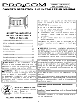
14
CAUTION
Always refer to the heater’s electrical connection diagram when servicing to avoid wiring errors and heater malfunction.
Check for proper operation after servicing.
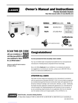
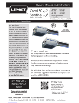
Electrical Connection and Ladder Diagram
MOTOR
MOTOR YELLOW
BLACK
GAS
CONTROL
VALVE
POWER
CORD
WHITE
BLACK
GREEN
GROUND GROUND
THERMOSTAT
RED
RED
YELLOW
BLACK
WHITE
BLACK
ELECTRICAL CONNECTION DIAGRAM
ELECTRICAL LADDER DIAGRAM
IF ANY OF THE ORIGINAL WIRES AS SUPPLIED WITH THE HEATER MUST BE
REPLACED, IT MUST BE REPLACED WITH WIRING MATERIAL HAVING A
TEMPERATURE RATING OF AT LEAST 302°F (150°C)
ELECTRICAL CONNECTION DIAGRAM
MOTOR
RED
GAS
CONTROL
VALVE
POWER
CORD
GROUND THERMOSTAT GROUND
RED
WHITE
BLACK
GREEN
YELLOW
WHITE
BLACK
ELECTRICAL LADDER DIAGRAM
ELECTRICAL LADDER DIAGRAM ELECTRICAL LADDER DIAGRAM
ELECTRICAL CONNECTION DIAGRAM
ELECTRICAL CONNECTION DIAGRAM
ATTENTION
■The following wiring diagrams apply to heater Models
326 and 330.
■Heater Models 324 and 326 do not ship with a
thermostat or gas control solenoid. The heater’s motor
plugs directly to an approved electrical source.
Model 330
Model 326

15
PROBLEMS CAUSES REMEDIES
1. Pilot will not light. * LP-Gas tank empty. * Fill LP-Gas tank.
* Gas supply valve closed. * Open supply valve.
* Pilot control valve button not fully * Fully depress the pilot button.
depressed.
* Restriction in gas hose. * Replace hose or blow out with
compressed air.
* Pilot light orifice or screen plugged. * Clean orifice or screen with
compressed air, or replace orifice or screen if
necessary.
* Air in gas line. * Depress pilot button on pilot control
valve to bleed the air from the gas line.
Usually necessary at time of
installation.
* Excess flow valve in P.O.L. * Close LP-Gas tank valve, wait
stem closed. 5 minutes and reopen valve slowly.
* Pilot control valve defective. * Replace pilot control valve.
2. Pilot light will not stay lit when * Restriction in gas hose. * Replace hose or blow out with.
pilot control valve is released. compressed air.
* Loose thermocouple. * Tighten thermocouple.(1)
* Weak or defective thermocouple. * Replace thermocouple.(1)
* Pilot light orifice or screen partially * Clean orifice or screen with
compressed plugged. air replace pilot orifice or screen if
necessary.
* Defective pilot control valve. * Replace pilot control valve.
* Debris plugging up pilot screen. * Replace pilot screen.
3. Pilot light will not stay lit when main * Pilot light orifice or screen partially * Clean orifice or screen with
compressed
burner and blower are operating. plugged. air or replace pilot orifice or screen if
necessary.
* Improper gas pressure. * Set pressure according to Owner's
Manual or dataplate on heater.
* Weak or defective thermocouple. * Replace thermocouple.(1)
* Loose thermocouple. * Tighten thermocouple connection.(1)
4. Heater blowing cold air with pilot * LP-Gas tank empty. * Fill LP-Gas tank.
light out. * Obstruction in gas line. * Clean the gas line.
* Freeze up of LP gas tank. * Use larger LP gas tank. Keep tank
full on cold nights.
5. Motor overheating and shutting off. * Thermal overload switch in motor * Thermal overload switch in motor
is opening. opening due to:
a. High voltage - check voltage supply
against heater voltage requirements.
b. Dirty motor - clean motor housing.
c. If motor has oil ports, put several
drops of SAE 20 wt. non-detergent
oil in each oil hole.
Troubleshooting Information

6. Heater blowing cold air with pilot * Defective solenoid valve. * Replace solenoid valve.
light burning. (Models 326 and 330)
* Main burner valve not open * Open main burner valve
7. Main burner does not shut * Defective solenoid valve. * Replace solenoid valve.
off when thermostat is
satisfied. (Models 326 * Defective thermostat. * Replace thermostat.
and 330) * Gas pressure too high. * Check nameplate on heater for
correct gas pressure.
8. Gas solenoid valve "chatters". * Defective solenoid in gas valve. * Replace solenoid valve.
(Models 326 and 330) * Gas pressure too high. * Check dataplate on heater for correct
type of gas and operating pressure.
* Improper (low) voltage. * Check voltage supply against unit
voltage requirements.
(1) Tighten the thermocouple nut finger tight and snug in place with appropriate wrench. DO NOT OVERTIGHTEN.
(2) With any electrical problem, all wiring should be checked for good connections and proper voltage and repaired if a
problem is found.
16

Heater Component Function
Burner
Cast iron component used to channel gas and provide an
area at which the fuel may ignite.
Burner Orifice
Brass metering device used to feed gas to burner at a
specific rate.
Fan
Component used in conjunction with the motor to pull the
hot air from heater and blow it into room for heating.
Gas Hose
Flexible connector used to convey gas from supply line in
building to heater.
Motor
Electric device used to force preheated air through the
heater and to circulate heat within a certain area. Converts
electrical energy into mechanical energy.
Pilot Light Orifice
A metering device used to supply gas for the dual purpose of
igniting the main burner and heating the thermocouple.
Pilot Safety Control Valve
A gas control valve which is held open by electrical power
supplied by a pilot generator and which closes automatically
to shut off the flow of gas to the main burner when the pilot
flame is extinguished or becomes too small to light the main
burner.
Pilot Tube
Formed copper tube used to convey gas from the safety
control valve to the pilot light orifice. The tube is internally
“tinned” when natural gas is used to resist the effects of
sulphur in the fuel.
Regulator
The heart of any gas supply installation. Used to deliver a
working pressure to the appliance under varying conditions
in tank pressure.
Solenoid Valve
Electromagnet which when energized by electrical current
opens and allows gas to pass through to the burner for
ignition.
Thermocouple
A thermoelectric device that converts heat energy directly
into electrical energy. Works in conjunction with the
electromagnet in the gas control valve thereby providing gas
supply for the pilot light.
Thermostat
Electrical device used as an automatic “on/off” switch
which will respond to changes in temperature in a certain
area. Can be wired so contacts in the thermostat open or
close on temperature increase or decrease.
17


PARTS LIST
Models
Item Description 324 326 328 330
1 Nut -----------------------------------------------130-01237---------------------------------
2 Screw -----------------------------------------------130-02747----------------------------------
3 Motor -----------------------------------------------550-07181---------------------------------
4 Fan -----------------------------------------------420-01227---------------------------------
5 Set Screw -----------------------------------------------130-01235---------------------------------
6 Regulator -----------------------------------------------550-21788---------------------------------
7 Adapter, Hose -----------------------------------------------310-01098---------------------------------
8 Hose, 1/4 in. ID x 10ft. -------------550-20720------------- -------------400-20242------------
9 Cord, Power 120-04645 120-07040 120-04654 120-07040
10 Valve, Pilot Safety -----------------------------------------------130-07966---------------------------------
11 Adapter -----------------------------------------------310-07970---------------------------------
12 Panel N/A 230-02693 N/A 230-02693
13 Thermostat -----------------------------------------------500-06537---------------------------------
14 Bracket N/A 230-02063 N/A 230-02063
15 Elbow N/A 130-07968 N/A 130-07968
16 Valve, Solenoid N/A 120-02990 N/A 120-02990
17 Wheel -----------------------------------------------130-01099--------------------------------
18 Elbow N/A 130-01300 N/A 130-01300
19 Nipple N/A 130-01142 N/A 130-01142
20 Valve ------------------------------------------------130-20229--------------------------------
21 Connector N/A 130-04648 N/A 130-04648
22 Tube w/Nuts N/A 500-20406 N/A 500-20406
23 Elbow N/A 130-01300 N/a 130-01300
24 Orifice, Burner -------------310-01591------------- -------------310-03415------------
25 Nut, Jam -----------------------------------------------130-09379---------------------------------
26 Thermocouple 120-01090 120-01020 120-01090 120-01020
27 Screw -----------------------------------------------130-01213---------------------------------
28 Tubing, Pilot w/Nuts 550-07073 550-07075 550-07076 550-07075
29 Screen, Pilot -----------------------------------------------130-01722---------------------------------
30 Orifice, Pilot (w/Screen) -----------------------------------------------400-01230---------------------------------
31 Bracket, Pilot -----------------------------------------------400-03202---------------------------------
32 Head, Pilot -----------------------------------------------310-01079---------------------------------
33 Burner -------------320-01337------------- -------------320-01228------------
34 Duct --------------400-01334------------ N/A N/A
35 Case Assembly w/Labels 500-22339 500-22340 500-22341 500-22342
N/A - Not Applicable
19

Contact your local L.B. White dealer for replacement parts
and service or call the L.B. White Co., Inc. at 1-800-345-7200
for assistance. Be sure that you have your heater model
number and configuration number when calling.
20
L.B. White Co., Inc. warrants that the component parts of its
heater are free from defects in material and workmanship,
when properly installed, operated, and maintained in
accordance with the Owner’s Manual safety guides and
labels contained with each unit. If, within 112 mmonths ffrom
the ddate oof ppurchase bby tthe eend uuser, any component is
found to be defective, L.B. White Co., Inc. will at its option,
repair or replace the defective part or heater, with a new
part or heater, F.O.B., Onalaska, Wisconsin.
A warranty card on file at L.B. White will automatically
qualify the heater and its component parts for warranty
consideration. If a warranty card is not on file, a copy of the
bill of sale will be required to establish warranty
qualification. If neither is available, the warranty period will
be 12 months from date of shipment from L B. White.
Warranty Policy
Replacement Parts and Service
EQUIPMENT
PARTS
L.B. White Co., Inc. warrants that replacement parts
purchased from the company and used on the appropriate
L. B. White heater are free from defects both in material and
workmanship for 12 mmonths ffrom tthe ddate oof ppurchase bby
the eend uuser. Warranty is automatic if a component is found
defective within 12 months of the date code marked on the
part. If the defect occurs more than 12 months later than
the date code but within 12 months from the date of
purchase by the end user, a copy of a bill of sale will be
required to establish warranty qualification.
The warranty set forth above is the exclusive warranty
provided by L.B. White, and all other warranties, including
any implied warranties or merchantability or fitness for a
particular purpose, are expressly disclaimed. In the event
any implied warranty is not hereby effectively disclaimed
due to operation of law, such implied warranty is limited in
duration to the duration of the applicable warranty stated
above. The remedies set forth above are the sole and
exclusive remedies available hereunder. L.B. White will not
be liable for any incidental or consequential damages
directly or indirectly related to the sale, handling or use of
the heater, and in any event L.B. White's liability in
connection with the heater, including for claims based on
negligence or strict liability, is limited to the purchase price.
Some states do not allow limitations on how long an implied
warranty lasts, so the above limitation may not apply to you.
Some states do not allow the exclusion or limitation of
incidental or consequential damages, so the above
limitation or exclusion may not apply to you. This warranty
gives you specific legal rights, and you may also have other
rights which vary from state to state.
-
 1
1
-
 2
2
-
 3
3
-
 4
4
-
 5
5
-
 6
6
-
 7
7
-
 8
8
-
 9
9
-
 10
10
-
 11
11
-
 12
12
-
 13
13
-
 14
14
-
 15
15
-
 16
16
-
 17
17
-
 18
18
-
 19
19
-
 20
20


L.B. White Jet 200 Owner's Manual And Instructions
- Type
- Owner's Manual And Instructions
Ask a question and I''ll find the answer in the document
Finding information in a document is now easier with AI
Related papers
-
 L.B. White 379 Installation and Service Manual
-
 L.B. White Therma Grow HW220 Owner's Manual And Instructions
-
 L.B. White Therma Grow HW120 Owner's Manual And Instructions
-
 L.B. White Premier TS170 Owner's manual
-
 L.B. White Sentinel AT 125 Owner's Manual And Instructions
-
 L.B. White Director CP300AKI Owner's Manual And Instructions
-
 L.B. White CP210AK Owner's Manual And Instructions
-
 L.B.White Oval 80 v.2 Owner's Manual And Instructions
-
 L.B. White CS170 Owner's Manual And Instructions
-
 L.B. White i34 Owner's Manual and Installation Instructions


Other documents
-
White Outdoor FUEL HD120 User manual
-
C3 Technology 185874-001 User manual
-
 Universal SPC125-R User manual
-
Reliance Water Heaters 2919340 User manual
-
Kenmore 153.33385 User manual
-
Desa Tech TC100VRNG Owner's manual
-
State 186489-002 User manual
-
Kenmore POWER MISER 9 153.339572 User manual
-
 ProCom Heating QN300TYLA User manual
-

