

Please direct all enquiries to your
local Wavetek Wandel Goltermann sales
company. The addresses are given at the
end of this handbook.
Copyrights
This product or parts of it are based upon
Recommendations and/or Standards of the
Standardization Sector of the International
Telecommunication Union - ITU-T and/or of the
European Telecommunications Standards Institute -
ETSI. These Recommendations and Standards are
subject to copyrights of these organizations. Without
written permission of the ITU-T and/or ETSI it is not
permitted to copy ITU-T Recommendations or ETSI
standards or parts thereof and/or make them available
to third parties.
Wavetek Wandel Goltermann
Eningen GmbH & Co.
Mühleweg 5, 72800 Eningen u. A.
© 2000
Author: MDD/TD
Translator: John Nutley
Order no.: BN 3035/98.32
Edition: 06/00.07 (V 7.20)
Previous edition:
05/00.04 (V 7.10)
Subject to change without notice
Our normal guarantee and delivery
terms apply
Printed in Germany

ANT-20/ANT-20E Broadband Analyzer/Generator
i
Contents
Introduction
1 Main applications of the Broadband Analyzer/Generator . . . . . . . .I-1
2 Application concept . . . . . . . . . . . . . . . . . . . . . . . . . . . . . . . . . . . . . . .I-2
3 Test applications . . . . . . . . . . . . . . . . . . . . . . . . . . . . . . . . . . . . . . . . .I-5
3.1 ATM performance analysis . . . . . . . . . . . . . . . . . . . . . . . . . . .I-5
3.2 Traffic management tests . . . . . . . . . . . . . . . . . . . . . . . . . . . .I-5
3.3 UNI signaling tests . . . . . . . . . . . . . . . . . . . . . . . . . . . . . . . . .I-6
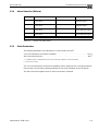
3.4 Analysis of ATM signals . . . . . . . . . . . . . . . . . . . . . . . . . . . . .I-6
3.5 Other fields of application . . . . . . . . . . . . . . . . . . . . . . . . . . . .I-6
4 Using and setting up the Broadband Analyzer/Generator . . . . . . . .I-7
5 Overview: Virtual Instruments, “VIs” . . . . . . . . . . . . . . . . . . . . . . . . .I-8
6 Often used terminology . . . . . . . . . . . . . . . . . . . . . . . . . . . . . . . . . . . .I-9
Operation
1 ATM Test Control . . . . . . . . . . . . . . . . . . . . . . . . . . . . . . . . . . . . . . . .O-1
1.1 Introduction . . . . . . . . . . . . . . . . . . . . . . . . . . . . . . . . . . . . . .O-1
1.2 “ATM Test Control” window layout and commands. . . . . . . .O-2
1.3 Important dialog windows . . . . . . . . . . . . . . . . . . . . . . . . . . .O-4
2 ATM Test Results . . . . . . . . . . . . . . . . . . . . . . . . . . . . . . . . . . . . . . . .O-7
2.1 Introduction . . . . . . . . . . . . . . . . . . . . . . . . . . . . . . . . . . . . . .O-7
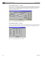
2.2 “ATM Test Results” main window layout and commands . . .O-7
2.3 Results window . . . . . . . . . . . . . . . . . . . . . . . . . . . . . . . . . . .O-9
3 ATM Channel Explorer. . . . . . . . . . . . . . . . . . . . . . . . . . . . . . . . . . .O-11
3.1 Introduction . . . . . . . . . . . . . . . . . . . . . . . . . . . . . . . . . . . . .O-11
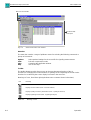
3.2 “ATM Channel Explorer” window layout and commands . .O-12
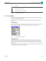
3.3 Results window . . . . . . . . . . . . . . . . . . . . . . . . . . . . . . . . . .O-14

Broadband Analyzer/Generator ANT-20/ANT-20E
ii
4 Port configurations (topologies) and
Instrument Configuration . . . . . . . . . . . . . . . . . . . . . . . . . . . . . . . .O-16
4.1 Overview. . . . . . . . . . . . . . . . . . . . . . . . . . . . . . . . . . . . . . .O-16
4.2 The “Instrument Configuration” dialog . . . . . . . . . . . . . . . .O-16
4.3 Port configuration . . . . . . . . . . . . . . . . . . . . . . . . . . . . . . . .O-17
4.4 Tx/Rx Configuration . . . . . . . . . . . . . . . . . . . . . . . . . . . . . .O-19
4.4.1 The “ATM Layer” dialog . . . . . . . . . . . . . . . . . . . . . . . . . . .O-19
4.4.2 “Edit Signal Structure”. . . . . . . . . . . . . . . . . . . . . . . . . . . . .O-21
4.5 Signaling emulation. . . . . . . . . . . . . . . . . . . . . . . . . . . . . . .O-21
4.5.1 The “Signaling Protocol” dialog. . . . . . . . . . . . . . . . . . . . . .O-21
4.5.2 The “Address Input” dialog . . . . . . . . . . . . . . . . . . . . . . . . .O-22
5 Test Types . . . . . . . . . . . . . . . . . . . . . . . . . . . . . . . . . . . . . . . . . . . .O-25
5.1 Overview. . . . . . . . . . . . . . . . . . . . . . . . . . . . . . . . . . . . . . .O-25
5.2 The “Test Setup” dialog: Setting the Test Type . . . . . . . . .O-26
5.3 The “ATM Layer QoS - Looped Topology” test type. . . . . .O-27
5.4 The “ATM Layer QoS (PVC) - Point-to-point” test type. . . .O-28
5.5 The “ATM Layer QoS (PVC) - Looped” test type . . . . . . . .O-29
5.6 The “ATM Layer QoS (SVC) - Calling” test type. . . . . . . . .O-30
5.7 The “ATM Layer QoS (SVC) - Called” test type . . . . . . . . .O-30
5.8 The “ATM Layer QoS (SVC) - Self Call” test type. . . . . . . .O-31
5.9 The “Test Setup <...>” dialog: Configure test type . . . . . . .O-32
5.9.1 Select channel . . . . . . . . . . . . . . . . . . . . . . . . . . . . . . . . . .O-33
5.9.2 Header . . . . . . . . . . . . . . . . . . . . . . . . . . . . . . . . . . . . . . . .O-34
5.9.3 Called party address. . . . . . . . . . . . . . . . . . . . . . . . . . . . . .O-35
5.9.4 Own instrument address. . . . . . . . . . . . . . . . . . . . . . . . . . .O-35
5.9.5 Source parameters . . . . . . . . . . . . . . . . . . . . . . . . . . . . . . .O-36
5.9.6 Multiplexer. . . . . . . . . . . . . . . . . . . . . . . . . . . . . . . . . . . . . .O-37
5.9.7 Channel labeling. . . . . . . . . . . . . . . . . . . . . . . . . . . . . . . . .O-37
6 Defining Virtual Channels . . . . . . . . . . . . . . . . . . . . . . . . . . . . . . . .O-38
6.1 Overview. . . . . . . . . . . . . . . . . . . . . . . . . . . . . . . . . . . . . . .O-38
6.2 The “Channel Editor” dialog . . . . . . . . . . . . . . . . . . . . . . . .O-38
6.3 Parameter display and modification (index cards) . . . . . . .O-40
6.3.1 The “General” index card . . . . . . . . . . . . . . . . . . . . . . . . . .O-40

ANT-20/ANT-20E Broadband Analyzer/Generator
iii
6.3.2 The “Header/Address” index card. . . . . . . . . . . . . . . . . . . .O-41
6.3.3 The “Traffic Contract” index card. . . . . . . . . . . . . . . . . . . . .O-43
6.3.4 The “Traffic Contract” index card (continued) . . . . . . . . . . .O-44
6.3.5 The “Traffic Source” index card. . . . . . . . . . . . . . . . . . . . . .O-45
Application Guide
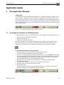
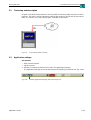
1 The Application Manager. . . . . . . . . . . . . . . . . . . . . . . . . . . . . . . . . .A-1
1.1 Selecting the Instruments for ATM Applications . . . . . . . . . .A-1
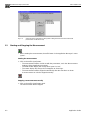
1.2 Starting and Stopping the Measurement. . . . . . . . . . . . . . . .A-2
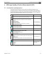
2 ATM Layer Quality of Service Measurements (SVC). . . . . . . . . . . .A-3
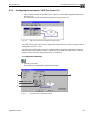
2.1 Overview: Basic operating sequence . . . . . . . . . . . . . . . . . . A-3
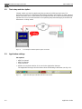
2.2 Test setup and description . . . . . . . . . . . . . . . . . . . . . . . . . .A-4
2.3 Application settings . . . . . . . . . . . . . . . . . . . . . . . . . . . . . . . . A-4
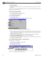
2.3.1 Configuring the Instrument: “ATM Test Control” VI. . . . . . . .A-5
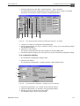
2.3.2 Selecting the Test Type: “ATM Test Control” VI . . . . . . . . . .A-9
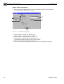
2.3.3 Configuring the Test Type: “ATM Test Control” VI . . . . . . .A-10
2.4 Enabling and Disabling Test Traffic:
“ATM Test Control” VI . . . . . . . . . . . . . . . . . . . . . . . . . . . . .A-12
2.5 Editing Test Parameters “On-Line”:
“ATM Test Control” VI . . . . . . . . . . . . . . . . . . . . . . . . . . . . .A-13
2.6 Inserting Errors: “ATM Test Control” VI. . . . . . . . . . . . . . . .A-14
2.7 Displaying the Results: “ATM Test Results” VI . . . . . . . . . .A-15
2.7.1 Preparing to Record Results. . . . . . . . . . . . . . . . . . . . . . . .A-15
2.7.2 Displaying the Signaling Analysis . . . . . . . . . . . . . . . . . . . .A-16
2.7.3 The “Quality Of Service” window. . . . . . . . . . . . . . . . . . . . .A-18
2.7.4 The “Receiver Status” window . . . . . . . . . . . . . . . . . . . . . .A-20
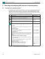
3 Detecting and analyzing ATM channels (Channel Explorer) . . . .A-22
3.1 Overview: Basic operating sequence . . . . . . . . . . . . . . . . .A-22
3.2 Test setup and description . . . . . . . . . . . . . . . . . . . . . . . . .A-23
3.3 Application settings . . . . . . . . . . . . . . . . . . . . . . . . . . . . . . .A-23
3.4 Measurement . . . . . . . . . . . . . . . . . . . . . . . . . . . . . . . . . . .A-24
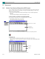
3.4.1 “Activity” Scan:
Detect and Display Active ATM Channels. . . . . . . . . . . . . .A-24
3.4.2 Analyzing the AAL types of active ATM channels. . . . . . . .A-25
3.4.3 Displaying the AAL Type Distribution . . . . . . . . . . . . . . . . .A-26

Broadband Analyzer/Generator ANT-20/ANT-20E
iv
3.4.4 Trouble Scan: Detecting and displaying
ATM Channels where alarms are present . . . . . . . . . . . . . A-27
3.5 Selecting Options . . . . . . . . . . . . . . . . . . . . . . . . . . . . . . . . A-29
3.6 Sorting Channels . . . . . . . . . . . . . . . . . . . . . . . . . . . . . . . . A-30
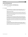
Technical Background
1 ATM Traffic Generation and Multiplexing . . . . . . . . . . . . . . . . . . .TB-1
1.1 Overview. . . . . . . . . . . . . . . . . . . . . . . . . . . . . . . . . . . . . . . TB-1
1.2 Generator Principle. . . . . . . . . . . . . . . . . . . . . . . . . . . . . . . TB-2
1.3 Source Models . . . . . . . . . . . . . . . . . . . . . . . . . . . . . . . . . . TB-2
1.3.1 “Constant Bit Rate” source model. . . . . . . . . . . . . . . . . . . . TB-3
1.3.2 “On-Off” source model . . . . . . . . . . . . . . . . . . . . . . . . . . . . TB-4
1.4 Traffic Control and Multiplexing Method . . . . . . . . . . . . . . . TB-5
1.5 Traffic Shaper . . . . . . . . . . . . . . . . . . . . . . . . . . . . . . . . . . . TB-8
2 Testing Switched Virtual Circuits (SVCs) . . . . . . . . . . . . . . . . . . .TB-9
2.1 General features of the signaling
(Software version 6.5) . . . . . . . . . . . . . . . . . . . . . . . . . . . . TB-9
2.2 Interoperability with other instruments . . . . . . . . . . . . . . . . TB-9
2.3 Starting and stopping signaling, generating test traffic. . . TB-10
2.4 “Calling” mode. . . . . . . . . . . . . . . . . . . . . . . . . . . . . . . . . . TB-10
2.5 “Called” mode . . . . . . . . . . . . . . . . . . . . . . . . . . . . . . . . . . TB-13
2.6 “Self Call” mode . . . . . . . . . . . . . . . . . . . . . . . . . . . . . . . . TB-15
Specifications “ATM Layer”
1 Generator . . . . . . . . . . . . . . . . . . . . . . . . . . . . . . . . . . . . . . . . . . . . . . S-1
1.1 Scrambling . . . . . . . . . . . . . . . . . . . . . . . . . . . . . . . . . . . . . . S-1
1.2 Fill Cells . . . . . . . . . . . . . . . . . . . . . . . . . . . . . . . . . . . . . . . . S-1
1.3 Cell Header. . . . . . . . . . . . . . . . . . . . . . . . . . . . . . . . . . . . . . S-1
1.4 General Functions. . . . . . . . . . . . . . . . . . . . . . . . . . . . . . . . . S-2
1.4.1 Error Insertion (Anomalies). . . . . . . . . . . . . . . . . . . . . . . . . . S-2
1.4.2 Alarm Generation (Defects) . . . . . . . . . . . . . . . . . . . . . . . . . S-2
1.5 Functions for
ATM Layer Quality of Service Measurements . . . . . . . . . . . S-3
1.5.1 General. . . . . . . . . . . . . . . . . . . . . . . . . . . . . . . . . . . . . . . . . S-3
1.5.2 Error Insertion (Anomalies). . . . . . . . . . . . . . . . . . . . . . . . . . S-3
1.5.3 Alarm Generation . . . . . . . . . . . . . . . . . . . . . . . . . . . . . . . . . S-3

ANT-20/ANT-20E Broadband Analyzer/Generator
v
1.5.4 Test Cell Format . . . . . . . . . . . . . . . . . . . . . . . . . . . . . . . . . .S-3
1.6 Source Models . . . . . . . . . . . . . . . . . . . . . . . . . . . . . . . . . . .S-4
1.6.1 Constant Bit Rate Model . . . . . . . . . . . . . . . . . . . . . . . . . . . .S-4
1.6.2 “On-Off” Model . . . . . . . . . . . . . . . . . . . . . . . . . . . . . . . . . . .S-4
1.7 Traffic Shaper . . . . . . . . . . . . . . . . . . . . . . . . . . . . . . . . . . . .S-5
1.7.1 Traffic Shaper for CBR, UBR and DBR Traffic Contracts . . .S-5
1.7.2 Traffic Shaper for VBR and SBR Traffic Contracts . . . . . . . .S-6
2 Receiver. . . . . . . . . . . . . . . . . . . . . . . . . . . . . . . . . . . . . . . . . . . . . . . . S-7
2.1 Descrambling . . . . . . . . . . . . . . . . . . . . . . . . . . . . . . . . . . . .S-7
2.2 General Functions. . . . . . . . . . . . . . . . . . . . . . . . . . . . . . . . .S-7
2.2.1 Error Measurements (Anomalies) . . . . . . . . . . . . . . . . . . . . .S-7
2.2.2 Alarm Detection (Defects). . . . . . . . . . . . . . . . . . . . . . . . . . .S-7
2.2.3 Receiver Bandwidth . . . . . . . . . . . . . . . . . . . . . . . . . . . . . . .S-7
2.3 ATM Layer Quality of Service Measurements. . . . . . . . . . . .S-8
2.3.1 General Features . . . . . . . . . . . . . . . . . . . . . . . . . . . . . . . . .S-8
2.3.2 Error Related Parameters . . . . . . . . . . . . . . . . . . . . . . . . . . .S-8
2.3.3 Delay Related Parameters . . . . . . . . . . . . . . . . . . . . . . . . . .S-8
2.3.4 Alarm Detection (Defects). . . . . . . . . . . . . . . . . . . . . . . . . . .S-9
2.3.5 Other Parameters . . . . . . . . . . . . . . . . . . . . . . . . . . . . . . . . .S-9
2.4 Channel Explorer. . . . . . . . . . . . . . . . . . . . . . . . . . . . . . . . .S-10
2.4.1 Activity Scan . . . . . . . . . . . . . . . . . . . . . . . . . . . . . . . . . . . .S-10
2.4.2 Trouble Scan. . . . . . . . . . . . . . . . . . . . . . . . . . . . . . . . . . . .S-10
2.4.3 AAL analysis . . . . . . . . . . . . . . . . . . . . . . . . . . . . . . . . . . . .S-11
3 Signaling . . . . . . . . . . . . . . . . . . . . . . . . . . . . . . . . . . . . . . . . . . . . . .S-12
3.1 Traffic Contracts . . . . . . . . . . . . . . . . . . . . . . . . . . . . . . . . .S-12
3.2 Signaling Analysis. . . . . . . . . . . . . . . . . . . . . . . . . . . . . . . .S-12
Index

Broadband Analyzer/Generator ANT-20/ANT-20E
vi
Notes:

ANT-20/ANT-20E Broadband Analyzer/Generator
Introduction I-1
Introduction
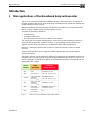
1 Main applications of the Broadband Analyzer/Generator
ATM is set to change the landscape in WANs and LANs in the coming years. Practically all
network operators view ATM as a key technology in enabling them to provide the required high
quality standard in future services.
With the Broadband Analyzer/Generator the right tool is provided to you for performing ATM
tests in a simply, reliably manner and with highest accuracy.
The tester is particularly suitable for
• commissioning,
• acceptance testing and
• in-service testing of ATM services, switches and networks.
This means that your network management is enhanced to provide performance tests that
guarantee the best possible “Quality of Service”. A special feature, the real-time function
supports the test, which also allows you to optimize the ATM traffic management.
Both SVCs (Switched Virtual Circuits) and PVCs (Permanent Virtual Circuits) are tested
precisely.
Testing of different ATM service categories will be supported directly by the Broadband
Analyzer/Generator.
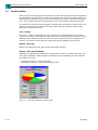
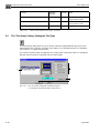
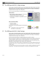
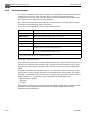
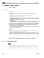
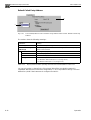
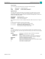
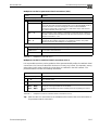
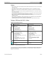
ATM traffic contracts can be analyzed in detail and can therefore be guaranteed by means of an
acceptance test. The figure below shows the relationship between the ATM Forum and ITU-T
service categories, their traffic descriptions and the minimum guarantee corresponding to the
appropriate traffic contract.
Fig. I-1 Features of ITU-T and ATM Forum traffic contracts
Service
Bandwidth, min CLR
Category
Traffic
Description
Guarantees
Quality of Service
max CTD, CDV
peak-to-peak
CBR
DBR
nrt-VBR
CBR
ABR
UBR
PCR
and CDVT
PCR
PCR, SCR, MBS
CDVT
BCR
PCR, MCR
and CDVT
PCR
and CDVT
PCR
PCR, MCR
and CDVT
PCR
PCR, SCR, MBS
CDVT
BCR
and CDVT
PCR
Bandwidth, min CLR
max CTD, CDV
peak-to-peak
Bandwidth, low CLR for
conforming sources
Bandwidth, min CLR
No

Broadband Analyzer/Generator ANT-20/ANT-20E
I-2 Introduction
All the test applications have been developed in accordance with the latest information from the
standardization bodies ATM Forum and ITU-T to ensure that they are always up to date.
Your Wavetek Wandel Goltermann Sales Partner can supply the latest information about
software upgrades and new options to keep you abreast of the latest developments in ATM test
technology.
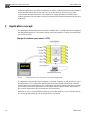
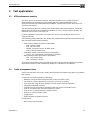
2 Application concept
The Broadband Analyzer/Generator in the ANT-20/ANT-20E is an ATM tester that is equipped
with integrated interfaces. This ensures that the necessary interface is easily accessible when
you are on the move.
Fig. I-2 Comprehensive choice of interfaces for the ANT-20/ANT-20E
The Broadband Analyzer/Generator operates in “Emulate” mode for an UNI interface for most
test applications. This configuration provides the test instrument with characteristics that are
similar to those of an ATM terminal. This configuration also allows signaling emulation to enable
you to make performance measurements using ATM switched virtual circuits. The function is
also used for testing the major characteristics of ATM switches.
ATM tests on SVCs can be performed faster and more effectively since you no longer need to
be concerned with setting up and clearing down the connection.

ANT-20/ANT-20E Broadband Analyzer/Generator
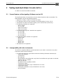
Introduction I-3
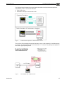
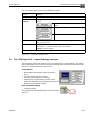
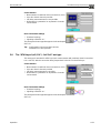
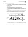
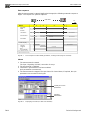
The diagram below illustrates the steps that the Broadband Analyzer/Generator performs
automatically, when a self-call was initiated:
1. Test circuit set up
2. Performance analysis over the test circuit
Fig. I-3 Automatic test sequence for switched virtual circuits
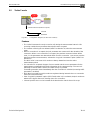
The receiver of the Broadband Analyzer/Generator can be used separately for troubleshooting
or analysis. The ANT-20/ANT-20E can be used with a “T” connector or optical power splitter for
this monitor type operating mode.
Fig. I-4 ANT-20/ANT-20E monitor function

Broadband Analyzer/Generator ANT-20/ANT-20E
I-4 Introduction
All test applications are supported by a practical application and channel database. In the
simplest scenario, an application is called up and started directly.
With the ATM channel editor a comfortable tool for the extension and handling of the ATM
channel database is available.
The results must be recorded, not just for acceptance tests. All the virtual instruments of the
Broadband Analyzer/Generator include a print function to allow you to produce hard copies that
can be used for presentations.
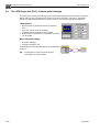
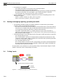
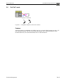
The Broadband Analyzer/Generator is particularly suitable for end to end or Multicall test
applications. The concept allows new connections, network nodes or network terminations to be
tested simply and reliably on the customer’s premises. These tests can also be automated if
they are performed using signaling and SVCs.
Fig. I-5 Multicall applications using the Broadband Analyzer/Generator
Several Broadband Analyzer/Generators are calling a “Call-server”
OMC: Operation & Maintenance Center

ANT-20/ANT-20E Broadband Analyzer/Generator
Introduction I-5
3 Test applications
3.1 ATM performance analysis
The basic version of the tester supports analysis of the ATM layer “Quality of Service”.
Measurements are performed in conformance with ITU-T Recommendation O.191,
“SPECIFICATIONS OF MEASURING EQUIPMENT; Equipment to Assess ATM Layer Cell
Transfer Performance”.
This standard describes the currently most reliable ATM measurement method. It basically
defines test cell formats and evaluation algorithms such as a 4-byte sequence number, the
timestamp and a CRC16 check per cell.
By these definitions, test results in accordance to O.191 were registered, which can be
compared directly.
The following quality parameters are reliably and unambiguously determined from the test cell
data using the measurement algorithm:
• Error-related network performance parameters
– CER, Cell Error Ratio
– CLR, Cell Loss Ratio
– SECBR, Severely Errored Cell Block Ratio
– CMR, Cell Misinsertion Rate
• Availability-related network performance parameters
– LPAC, Loss of Performance Assessment Capability
• Delay-related network performance parameters
– CTD, Cell Transfer Delay
– CDV, Cell Delay Variation
Using this measurement method, particularly precise long term measurements are possible
which allow evidence of the constant high quality of a connection to be obtained.
3.2 Traffic management tests
Various test functions assist you in testing the ATM traffic management functions or to optimize
their settings.
In particular, the tester supports the following:
• Definition and agreement of the ATM traffic contract for ATM circuits
• Checking the contract guarantees: Cell rates, cell losses, cell delay
• Tests using the “leaky bucket” algorithm (GCRA, generic cell rate algorithm)
• Simulations with traffic shaping
• Compliance and conformance simulations with ATM circuits and ATM sources
• Tests in connection with connection admission control
• Tests of UPC (usage parameter control) functions
• Analysis of cell loss priority control
• Tagging tests
• Explicit forward congestion analysis
In preparation:
• AAL-5 frame discard testing

Broadband Analyzer/Generator ANT-20/ANT-20E
I-6 Introduction
3.3 UNI signaling tests
The “Signaling Emulation” function allows you to test the signaling characteristics of UNIs.
Signaling emulation provides a rapid “go/no go” assessment of the following:
• Is it possible to set up a connection?
• What address format is supported?
• Which contract parameters can be negotiated?
• Which service categories can be used?
• Does the signaling process operate without problems?
3.4 Analysis of ATM signals
The ATM Channel Explorer is used to analyze ATM signals. This tool, for example can perform
rapid diagnostics by finding the active ATM channels and displaying their bandwidth and AAL
distributions. A further application is the detection of defects and anomalies in the ATM signal.
3.5 Other fields of application
The range of applications for the Broadband Analyzer/Generator is very wide and includes the
following fields:
• Function tests for ATM network elements and modules
• Performance management
• Remote-controlled measurement of demand
• ATM network monitoring
• Acceptance tests
• Commissioning of ATM network nodes and ATM connections
• Commissioning of new ATM services

ANT-20/ANT-20E Broadband Analyzer/Generator
Introduction I-7
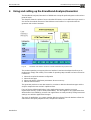
4 Using and setting up the Broadband Analyzer/Generator
The Broadband Analyzer/Generator is a flexible test concept for performing tests on the various
protocol layers.
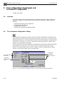
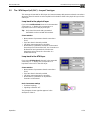
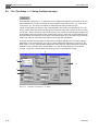
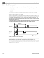
The diagram shows the points of access that the ATM tester can use within the layer model. It
also shows the modular structure of the Windows user interface in conjunction with the
generator and receiver hardware.
Fig. I-6 Hardware and software structure of the Broadband Analyzer/Generator
The modern operating concept and the user interface have been developed to allow you to
perform tests simply and reliably. The number of operating steps needed has been reduced to
a minimum:
1. Select the required instrument configuration
2. Select the test type
3. Select and edit the default test parameters where necessary
4. Start the measurement
The generator produces a test data stream in accordance with the selected test type and the
analyzer outputs the test results in optimized form.
If one of the pre-defined applications in the Application Manager matches your test
requirements exactly, it can be started immediately. This also applies to any applications that
will be defined or modified by yourself. Own applications are easily made by storing instrument
settings once with the Application Manager.
The stock of applications you create, together with the universal channel database allows the
ATM tester to be rapidly adapted to new, complex test situations.

Broadband Analyzer/Generator ANT-20/ANT-20E
I-8 Introduction
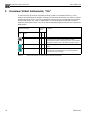
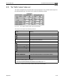
5 Overview: Virtual Instruments, “VIs”
To make it easier to locate and operate the large number of instrument functions, a user
interface was developed for the ANT-20 family of instruments that makes use of the concept of
virtual instruments or “VIs”. The VIs are designed so that each has a clearly defined set of tasks.
By selecting specific VIs, tools or “applications” can be developed and tailored to perform
particular measurement tasks. The VIs for the Broadband Analyzer/Generator are summarized
briefly below.
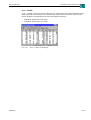
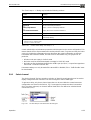
Table I-1 Virtual instruments for the Broadband Analyzer/Generator
Virtual instrument Protocol
layer
Function
Icon Name
Physical
ATM
Higher
ATM Test Control
•••
Configure the test connection, signaling emulation and
protocol layers for ATM measurements. Define
measurement modes and virtual channels. Control traffic
generation. Insert errors in the ATM and higher layers.
ATM Test Results
•••
Display and output the results of the ATM measurements
made.
ATM Channel Explorer
•••
Characterize ATM traffic at the standard interfaces and
trace alarms in the ATM layer (up to 1000 channels).
Perform AAL layer analysis.

ANT-20/ANT-20E Broadband Analyzer/Generator
Introduction I-9
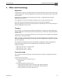
6 Often used terminology
Application
An application consists of a suitable collection of virtual instruments (VIs for short) used to solve
a measurement task. In this way applications can be defined e.g. for physical layer or ATM layer
measurements.
Applications are configured and managed in the “ANT20 - <Application Title>” window
(Application Manager VI).
If an application is saved, the parameter settings for the VIs used will also be saved.
In the same way, the measurement results are also saved with the application.
When the application is loaded, the test equipment is automatically set to the same settings as
when the application was last used.
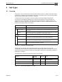
Test type
The “test type” is a concept used for ATM measurements. Test types are used to simply and
quickly configure the instrument and prevent operating errors, particularly if signaling emulation
is being used.
A test type consists of a measurement mode (only “ATM-Layer QoS” is available in this software
version) and a “connection mode”.
When a test type is selected, the instrument is pre-set for performing the measurement. A setup
dialog is provided for each test type so that you can make settings that are specific to the test
you want to perform.
The settings for all test types used are saved within an application. When an application is
loaded, the last test type used in the application will automatically be activated.
Example test types:
• ATM Layer QoS (PVC) - Point-to-point
• ATM Layer QoS (SVC) - Calling
• ATM Layer QoS (SVC) - Self-Call
Connection mode
The “connection mode” indicates the way that the virtual connection is switched through the
ATM layer.
Example connection modes:
• For permanent virtual connections (PVC):
– Point-to-point
– Looped
• For switched virtual connections SVC):
– Calling (switched point-to-point connection with calling instrument)
– Called (switched point-to-point connection with called instrument)
– Self-Call (switched connection with self-call)

Broadband Analyzer/Generator ANT-20/ANT-20E
I-10 Introduction
Port configuration
The Port configuration (topology) describes the way in which the test equipment is connected to
the device under test on the physical layer.
Example topologies:
• Emulate
• Looped (between generator and receiver)
• Monitor (not yet supported)
Traffic type
The traffic type indicates the type of traffic contract. This term is defined by the ATM Forum. The
ITU equivalent term is “broadband bearer capability”.
A traffic type must be specified for each virtual channel defined in the Channel Editor of the
“ATM Test Control” VI.
Example traffic types:
• CBR (constant bit rate)
• VBR-nRT (variable bit rate, non real time)
• DBR (deterministic bit rate)
• SBR (statistical bit rate)
The CBR and DBR traffic types are identical in most respects. This is also true of the VBR-nRT
and SBR traffic types.
Switched Virtual Circuit (SVC)
• Forward is the direction from the “calling” device to the “called” device.
• Backward is the direction from the “called” device to the “calling” device.
Permanent Virtual Circuit (PVC)
• Forward is the send direction of the device.
• Backward is the receiving direction of the device
Device means: ANT-20/ANT-20E.

ANT-20/ANT-20E Broadband Analyzer/Generator
Operation O-1
Operation
1 ATM Test Control
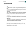
1.1 Introduction
Task
The “ATM Test Control” VI is used to select a test type and to configure the instrument for the
selected test type. You can also control the running of the test from this VI if the selected test
type allows for manual control (“Test - Online Control” dialog). Each test type generally includes
configuration of the generator and the receiver.
The instrument configuration covers selection of the port configuration (topology), setting the
various protocol layers, in particular the ATM layer and higher layers, as well as selection of the
type of connection, i.e. “permanent” or “switched”.
The “test types” available for selection are used to structure measurement types and connection
modes. These are arranged according to protocol layers, with only the ATM layer being
supported at present. Only those test types that are possible and practicable with the selected
instrument configuration are available for selection.
On-line control allows relevant test parameters to be altered during the traffic generation. This
is particularly useful for traffic parameters such as the peak cell rate or mean cell rate, allowing
rapid assessment of the effects of these parameters on the behavior of the device under test.
On-line control also allows errors (anomalies and defects) to be inserted into the test cell
stream.
The “ATM Test Control” VI is normally used together with the “ATM Test Results” VI. The latter
displays the test results as determined by the selected test type and corresponding instrument
configuration.
The settings made for a certain test type are saved within an “application” and are set again
automatically when the test is called up again. Bit error measurements in the physical layer are
not supported by the “ATM Test Control” VI.
Requirements
✓ The “Signal Structure” VI must also be loaded when performing ATM measurements. This is
used to control and configure the physical layer, e.g. select the bit rate, frame type, etc. The
instrument can also be configured for bit error measurements in the physical layer with the
“Signal Structure” VI. If the “ATM Test Control” VI is loaded, the “Signal Structure” VI can
only be accessed via the “Instrument Configuration” dialog of the “ATM Test Control” VI.
✓ To perform detailed tests in the physical layer, the “Anomaly/Defect Insertion” and “Anomaly/
Defect Analyzer” VIs should also be loaded. The “Anomaly/Defect Insertion” VI allows
insertion of a wide range of anomalies and defects in the physical layer. The “Anomaly/
Defect Analyzer” VI provides corresponding analysis of the anomalies and defects in the
physical layer.

Broadband Analyzer/Generator ANT-20/ANT-20E
O-2 Operation
Restrictions
The following virtual instruments cannot be used within a single application at the same time as
the “ATM Test Control” VI: “ATM Signal Structure”, “ATM Background Generator” and “ATM
Traffic Analyzer”
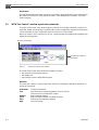
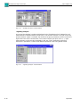
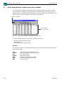
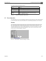
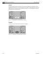
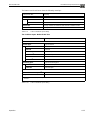
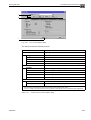
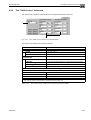
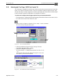
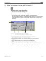
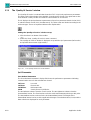
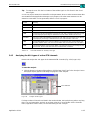
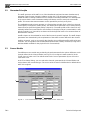
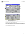
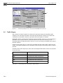
1.2 “ATM Test Control” window layout and commands
The “ATM Test Control” main window appears after the VI is loaded. It basically consists of a
menu bar, toolbar and workspace containing the current configuration diagram. Most functions
can be executed via menu commands (text) or via the icons in the toolbar.
When you select a menu command or an icon, a dialog window for making further settings may
appear in the foreground.
Fig. O-1 “ATM Test Control” main window
The “ATM Test Control” main window essentially consists of
• the menu bar and pull-down menus,
• the toolbar and
• the workspace with configuration diagram.
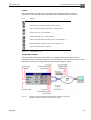
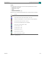
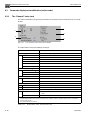
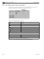
Menu bar
The menu bar contains a range of pull-down menus for selecting the following commands or
groups of commands:
Menu bar and toolbar
Configuration diagram/
workspace
Instrument Configure instrument
Test Select test type, set test parameters (on-line, off-line),
insert errors and control traffic enable
Options Select optional settings
Tools Define, handle and print out virtual channels
View Customize the application window
Help Use on-line help
Page is loading ...
Page is loading ...
Page is loading ...
Page is loading ...
Page is loading ...
Page is loading ...
Page is loading ...
Page is loading ...
Page is loading ...
Page is loading ...
Page is loading ...
Page is loading ...
Page is loading ...
Page is loading ...
Page is loading ...
Page is loading ...
Page is loading ...
Page is loading ...
Page is loading ...
Page is loading ...
Page is loading ...
Page is loading ...
Page is loading ...
Page is loading ...
Page is loading ...
Page is loading ...
Page is loading ...
Page is loading ...
Page is loading ...
Page is loading ...
Page is loading ...
Page is loading ...
Page is loading ...
Page is loading ...
Page is loading ...
Page is loading ...
Page is loading ...
Page is loading ...
Page is loading ...
Page is loading ...
Page is loading ...
Page is loading ...
Page is loading ...
Page is loading ...
Page is loading ...
Page is loading ...
Page is loading ...
Page is loading ...
Page is loading ...
Page is loading ...
Page is loading ...
Page is loading ...
Page is loading ...
Page is loading ...
Page is loading ...
Page is loading ...
Page is loading ...
Page is loading ...
Page is loading ...
Page is loading ...
Page is loading ...
Page is loading ...
Page is loading ...
Page is loading ...
Page is loading ...
Page is loading ...
Page is loading ...
Page is loading ...
Page is loading ...
Page is loading ...
Page is loading ...
Page is loading ...
Page is loading ...
Page is loading ...
Page is loading ...
Page is loading ...
Page is loading ...
Page is loading ...
Page is loading ...
Page is loading ...
Page is loading ...
Page is loading ...
Page is loading ...
Page is loading ...
Page is loading ...
Page is loading ...
Page is loading ...
Page is loading ...
Page is loading ...
Page is loading ...
Page is loading ...
Page is loading ...
Page is loading ...
Page is loading ...
Page is loading ...
Page is loading ...
Page is loading ...
Page is loading ...
Page is loading ...
Page is loading ...
Page is loading ...
Page is loading ...
Page is loading ...
Page is loading ...
Page is loading ...
Page is loading ...
-
 1
1
-
 2
2
-
 3
3
-
 4
4
-
 5
5
-
 6
6
-
 7
7
-
 8
8
-
 9
9
-
 10
10
-
 11
11
-
 12
12
-
 13
13
-
 14
14
-
 15
15
-
 16
16
-
 17
17
-
 18
18
-
 19
19
-
 20
20
-
 21
21
-
 22
22
-
 23
23
-
 24
24
-
 25
25
-
 26
26
-
 27
27
-
 28
28
-
 29
29
-
 30
30
-
 31
31
-
 32
32
-
 33
33
-
 34
34
-
 35
35
-
 36
36
-
 37
37
-
 38
38
-
 39
39
-
 40
40
-
 41
41
-
 42
42
-
 43
43
-
 44
44
-
 45
45
-
 46
46
-
 47
47
-
 48
48
-
 49
49
-
 50
50
-
 51
51
-
 52
52
-
 53
53
-
 54
54
-
 55
55
-
 56
56
-
 57
57
-
 58
58
-
 59
59
-
 60
60
-
 61
61
-
 62
62
-
 63
63
-
 64
64
-
 65
65
-
 66
66
-
 67
67
-
 68
68
-
 69
69
-
 70
70
-
 71
71
-
 72
72
-
 73
73
-
 74
74
-
 75
75
-
 76
76
-
 77
77
-
 78
78
-
 79
79
-
 80
80
-
 81
81
-
 82
82
-
 83
83
-
 84
84
-
 85
85
-
 86
86
-
 87
87
-
 88
88
-
 89
89
-
 90
90
-
 91
91
-
 92
92
-
 93
93
-
 94
94
-
 95
95
-
 96
96
-
 97
97
-
 98
98
-
 99
99
-
 100
100
-
 101
101
-
 102
102
-
 103
103
-
 104
104
-
 105
105
-
 106
106
-
 107
107
-
 108
108
-
 109
109
-
 110
110
-
 111
111
-
 112
112
-
 113
113
-
 114
114
-
 115
115
-
 116
116
-
 117
117
-
 118
118
-
 119
119
-
 120
120
-
 121
121
-
 122
122
-
 123
123
-
 124
124
-
 125
125
-
 126
126


Ask a question and I''ll find the answer in the document
Finding information in a document is now easier with AI
Related papers
Other documents
-
Amprobe DM-II PRO Software User manual
-
Cisco ACIP-SM(=) User manual
-
Aethra D2001 NX User manual
-
IBM ATM OC-3c User manual
-
Tektronix K15 Short Instructions
-
Adaptec ANA-5940 User manual
-
Panasonic 1200N User manual
-
-
JDS Uniphase IP Video Test Option HST-3000 User manual
-
 Cabletron Systems SFCS-1000 User manual
