Contents
1 General safety information................................... 2
2 External dimensions of the appliance................. 2
3 Side-by-side assembly.......................................... 2
The manufacturer works constantly on the further development
of all the types and models. Therefore please understand that
we have to reserve the right to make design, equipment and
technical modifications.
To get to know all the benefits of your new appliance, please
read the information contained in these instructions carefully.
The instructions apply to several models. Differences may
occur. Text relating only to specific appliances is marked with
an asterisk (*).
Instructions for action are marked with a
, the results of
action are marked with a .
1 General safety information
-
The socket must be easily accessible so that
the appliance can be quickly disconnected
from the supply in an emergency. It must be
outside the area of the rear of the appliance.
DANGER identifies a situation involving direct
danger which, if not obviated, may
result in death or severe bodily
injury.
WARNING identifies a dangerous situation
which, if not obviated, may result in
death or severe bodily injury.
CAUTION identifies a dangerous situation
which, if not obviated, may result in
minor or medium bodily injury.
NOTICE identifies a dangerous situation
which, if not obviated, may result in
damage to property.
Note identifies useful information and tips.
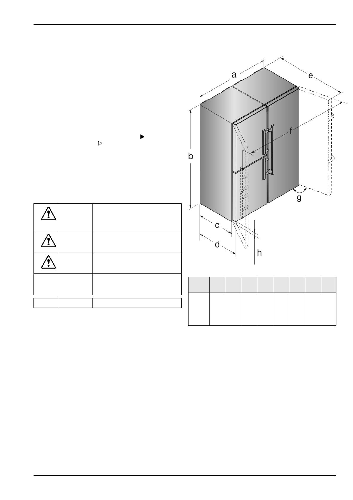
2 External dimensions of the
appliance
Fig. 1
Model a
[mm]
b
[mm]
c
[mm]
d
[mm]
e
[mm]
f
[mm]
g [°] h
[mm]
SBS(e
s/bs)
86..,
SBSes
84..
1210 1850
600
x
665
x
1185
x
1752 115 35
x
If you are using wall spacers, add 15 mm to the dimensions.
With the door open, the dimensions apply to an opening angle
of 115 °. Distances vary depending on the opening angle.
3 Side-by-side assembly
Install the freezer or the appliance with freezer compartment on
the left as viewed from the front. These appliances have a side-
wall heating on the right-hand side to prevent the formation of
condensation.
All the assembly components are supplied with the appliance.
Fitting parts in the accessory kit.
General safety information
2 * Depending on model and options


