Craftsman 919.167800 Owner's manual
- Category
- Air compressors
- Type
- Owner's manual

SEARS
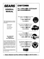
GENERAL
MANUAL
IMPORTANT:
Read the Safety Guidelines and
All Instructions Carefully Be-
fore Operating.
CRRFTSHRH
OIL LUBRICATED STATIONARY
AIR COMPRESSORS
° SAFETY GUIDELINES
• ASSEMBLY
° OPERATION
• MAINTENANCE
• TROUBLESHOOTING
Record in the spaces provided.
(1) The model numberwhich can be found
on the maintenance label on the front of
the air tank,
(2) The code number which (:zin_Se t_und
on the foil label on the right side of the
air tank,
(3) The Manufacturers Number (Mfg. No.)
(ASME code compressors only) is
located on the metal data plate which is
welded onto the left side of the air tank.
(This data plate is painted the same
color as the tank.)
Retain these numbers for future
reference.
Model No.
Code No.
Mfg. No.
Sears, Roebuck and Co., Hoffman E_ates, IL 60179 U.S.A.
D20437 Rev. 0 2/15/00

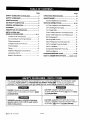
Page
SAFETY GUIDELINES-GUIDELINES ..................... 2
SAFETY GUIDELINES ............................................ 3
SPECIFICATIONS ................................................... 6
ON-RECEIPT INSPECTION ................................... 6
GENERAL INFORMATION ..................................... 6
GLOSSARY ............................................................. 7
DESCRIPTION OF OPERATION ............................ 7
INSTALLATION AND
BREAK-IN PROCEDURES ................ _.............. 8-11
Location of Air Compressor .............................. 8
Air Compressor Anchoring Methods ................. 8
Wiring Instructions ............................................. 9
Voltage and Circuit Protection .......................... 9
Wiring Diagram .................................................. 9
Piping ............................................................... 10
Additional Regulators and Controls ................. 11
Lubrication and Oil .......................................... 11
Break-in Procedures ........................................ 11
I
Page
OPERATING PROCEDURES ............................... 12
MAINTENANCE .................................................... 13
Routine Maintenance Schedule ....................... 13
SERVICE INSTRUCTIONS ............................. 14-16
Air Filter-Inspection and Replacement ............ 14
Oil-Checking and Changing ............................ 14
Two Stage Units .............................................. 14
=
Check Valve!- nspect on and Replacement ..... 14
Safety ValveHnspection and Replacement .....15
Belt-Replacement ............................................ 15
Adjusting Belt Tension ..................................... 15
Motor Pulleyi and Flywheel Alignment ............. 16
Motor Overlqad Protector-Reset ..................... 16
Motor Lubriqation ............................................ 16
Compressor jHead Bolts-Torquing .................. 16
Additional Service ............................................ 16
TROUBLESHOOTING GUIDE ........................ 17-20
=
HOW TO ORDER REPAIR PARTS ........ back cover
This manual contains information that is important for you to know and u
to protecting YOUR SAFETY and PREVENTING EQUIPMENT PROBLEI
information, we use the symbols to the right. Please read the manual
DANGER indicates an imminently hazardous
situation which, if not avoided, will result in death
or serious iniurv.
WARNING indicates a potentially hazardous
situation which, if not avoided, could result in
death of serious injury.
attention to these sections.
I
CAUTION indicates a potentially hazardous
situation which,iif not avoided, may result in minor
or moderate in!urv.
I
CAUTION usedi without the safety alert symbol
indicates a potentially hazardous situation which, if
not avoided, g31tLYresult in property damage.
i
I
r_0437 Rev. 0 2/15/00 2-ENG

IMPROPER OPERATION OR MAINTENANCE OF THIS PRODUCT COULD I:
AGE. READ AND UNDERSTAND ALL WARNINGS AND OPERATING
__J
IN SERIOUS INJURY AND PROPERTY DAM-
THJS EQUIPMENT.
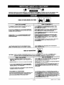
RISK OF EXPLOSION OR FIRE
• iiiiii lU ilUUl i
WHAT CAN HAPPEN
IT IS NORMAL FOR ELECTRICAL CONTACTS WITHIN THE
MOTOR AND PRESSURE SWITCH TO SPARK.
IF ELECTRICAL SPARKS FROM COMPRESSOR COME INTO
CONTACT WITH FLAMMABLE VAPORS, THEY MAY IGNITE,
CAUSING FIRE OR EXPLOSION.
RESTRICTING ANY OF THE COMPRESSOR VENTILATION
OPENINGS WILL CAUSE SERIOUS OVERHEATING AND
COULD CAUSE FIRE.
iii i
' ! HOW TO PREVENT IT
ALWAYS OPERATE THE COMPRESSOR IN A WELL VENTI-
LATED AREA FREE OF COMBUSTIBLE MATERIALS, GASO-
LINE OR SOLVENT VAPORS.
IF SPRAYLNG FLAMMABLE MATERIALS, LOCATE COMPRES-
SOR AT LEAST 20 FEET AWAY FROM SPRAY AREA. AN
ADDITIONAL LENGTH OF HOSE MAY BE REQUIRED.
i
STORE FLAMMABLE MATERIALS IN A SECURE LOCATION
AWAY FROM COMPRESSOR.
i I
NEVER PLACE OBJECTS AGAINST OR ON TOP OF COM-
PRESSOR_ OPERATE COMPRESSOR IN AN OPEN AREA AT
LEAST 12 INCHES AWAY FROM ANY WALL OR OBSTRUC-
TION THATIWOULD RESTRICT THE FLOW OF FRESH AIR TO
THE VENTILLATION OPENINGS.
OPERATE I_OMPRESSOR IN A CLEAN, DRY,WELL VENTILATED
AREA. DO NOT OPERATE UNIT INDOORS OR IN ANY
CONFINED AREA.
UNATTENDED OPERATION OF THIS PRODUCT COULD ALWAYS REMAIN IN ATTENDANCE WITH THE PRODUCT
RESULT IN PERSONAL INJURY OR PROPERTY DAMAGE. WHEN IT .1_OPERATING,
RISK OF BURSTING I_1
_: THE FOLLOWING CONDITIONS COULD LEAD TO A WEAKEiNING OF THE TANK, AND RESULT IN A ..........
VIOLENT TANK EXPLOSION AND COULD CAUSE PROPERTY DAMAGE OR SERIOUS INJURY.
WHAT CAN HAPPEN
f. FAILURE TO PROPERLY DRAIN CONDENSED WATER
FROM THE TANK, CAUSING RUST AND THINNING OF THE
STEEL TANK.
2. MODIFICATIONS OR ATTEMPTED REPAIRS TO THE TANK.
I Ilil
HOW TO PREVENT IT
i
DRAIN TANK DALLY OR AFTER EACH USE. IF TANK DEVELOPS
A LEAK REPLACE IT IMMEDIATELY WITH A NEW TANK OR
REPLACE THE ENTIRE COMPRESSOR.
NEVER DRILL INTO, WELD, OR MAKE ANY MODIFICATIONS-TO
THE TANK OR ITS A]-FACHMENTS.
THE TANK IS:DESIGNED TO WITHSTAND SPECIFIC OPEBATtNG
PRESSURe. NEVER MAKE ADJUSTMENTS OR PARTS
SUBSTITUT!ONS TO ALTER THE FACTORY SET OPERATING--
PRESSURES_
FOR ESSENTIAL CONTROL OF AIR PRESSURE, YOU MUST
IEGULATOR AND PRESSURE GAUGE
YOUR COMPRESSOR. FOLLOW THE
_ECOMMENDATION AND NEVER
BLE PRESSURE RATING OF
USE COMPRESSOR TO INFLATE SMALL
LOW-PRI :H AS CHILDREN'S TOYS,
BASKETBALLS. ETC.
J
3. UNAUTHORIZED MODIFICATIONS TO THE UNLOADER
VALVE, SAFETY VALVE, OR ANY OTHER COMPONENTS
WHICH CONTROL TANK PRESSURE.
4. EXCESSIVE VIBRATION CAN WEAKEN THE AIR TANK AND
CAUSE RUPTURE OR EXPLOSION.
ATTACHME_NTS & ACCESSORIES;
EXCEEDING THE PRESSURE RATING OF AIR TOOLS, SPRAY
GUNS, AIR OPERATED ACCESSORtES, TtRES AND OTHER
INFLATABLES CAN CAUSE THEM TO EXPLODE OR FLY
APART, AND COULD RESULT IN SERIOUS INJURY.
3-ENG D20437 Rev. 0 2/15/00

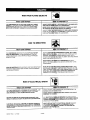
RISK FROM FLYING OBJECTS
llllllllU
WHAT CAN HAPPEN
THE COMPRESSED AIR STREAM CAN CAUSE SOFT TISSUE
DAMAGE TO EXPOSED SKIN AND CAN PROPEL DIRT, CHIPS,
LOOSE PARTICLES AND SMALL OBJECTS AT HIGH SPEED,
RESULTING IN PROPERTY DAMAGE OR PERSONAL INJURY.
I..............
I
ALWAYS WEAR ANS! 7.87.1 APPROVED SAFETY GLASSES WITH
SIDE SHIELDS WHEN USING THE COMPRESSOR.
NEVER POINT ANY _OZZLE OR SPRAYER TOWARD ANY PART
OF THE BODY OR _ OTHER PEOPLE OR ANIMALS.
ALWAYS TURN THE COMPRESSOR OFF AND BLEED PRESSURE
FROM THE AIR HOSI_;AND TANK BEFORE ATTEMPTING MAINTE-
NANCE, ATI'ACHIN_TOOLS OR ACCESSORIES.
i,
RISK TO BREATHING
WHAT CAN HAPPEN
THE COMPRESSED AIR FROM YOUR COMPRESSOR IS NOT
SAFE FOR BREATHING! THE _JR STREAM MAY CONTAIN
CARBON MONOXIDE, TOXIC VAPORS OR SOLID PARTICLES
FROM THE TANK.
SPRAYED MATERIALS SUCH AS PAINT, PAINT SOLVENTS, PAINT
REMOVER, INSECTICIDES, WEED KILLERS, CONTAIN HARMFUL
VAPORS AND POISONS.
H T PREVENT IT
ALWAYS OPERATE J ,IR COMPRESSOR OUTSIDE IN A CLEAN,
WELL VENTILATED i _EA. AVOID ENCLOSED AREAS SUCH AS
GARAGES, BASEMEr I_S, STORAGE SHEDS, WHICH LACK A
STEADY EXCHANGE :)F AIR. KEEP CHILDREN, PETS AND OTHERS
AWAY FROM AREA CF OPERATION.
NEVER INHALE AIR I_ROM THE COMPRESSOR EITHER DI-
/
RECTLY OR FROM A_REATHING DEVICE CONNECTED TO THE
COMPRESSOR.
WORK IN AN AREA WtTH GOOD CROSS-VENTILATION. READ
AND FOLLOW THE_FETY INSTRUCTIONS PROVIDED ON THE
LABEL OR SAFETY I:_TA SHEETS FOR THE MATERIAL YOU ARE
SPRAYING. USE A NI_OSH/MSHA APPROVED RESPIRATOR
DESIGNED FOR USE WIT=HYOUR SPECIFIC APPLICATION.
RISK OF ELECTRICAL SHOCK
WHATCAN HAPPEN
YOUR AIR COMPRESSOR IS POWERED BY ELECTRICITY. LIKE
ANY OTHER ELECTRtCALLY POWERED DEVICE, IF IT IS NOT
USED PROPERLY IT MAY CAUSE ELECTRIC SHOCK.
REPAIRS ATTEMPTED BY UNQUALIFIED PERSONNEL CAN
RESULT IN SERIOUS INJURY OR DEATH BY ELECTROCUTION,
ELECTRICAL GROUNDING: FAILURE TO PROVIDE ADEQUATE
GROUNDING TO THIS PRODUCT COULD RESULT IN SERIOUS
INJURY OR DEATH FROM ELECTROCUTION, SEE GROUNDING
INSTRUCTIONS.
lU
H
,,,WTO PREVENT IT
NEVER OPERATE THE]COMPRESSOR OUTDOORS WHEN IT IS
RAINING OR IN WET _ONDITIONS.
NEVER OPERATE COMPRESSOR WITH COVER COMPONENTS
REMOVED OR DAMA(_ED.
ANY ELECTRICAL WIRING OR REPAIRS REQUIRED ON THIS
PRODUCT SHOULD BE PERFORMED BY AUTHORIZED SERVICE
CENTER PERSONNE_ IN ACCORDANCE WITH NATIONAL AND
LOCAL ELECTRICAL qODES.
MAKE CERTAIN THAT THE ELECTRICAL CIRCUIT TO WHICH
THE COMPRESSOR IS[CONNECTED PROVIDES PROPER
ELECTRICAL GROUNDING, CORRECT VOLTAGE AND AD-
EQUATE FUSE PROTI_CTION.
D20437 Rev. 0 2/15/00 4-ENG

RISK FROM MOVING PARTSi
WHAT CAN HAPPEN
MOVING PARTS SUCH AS THE PULLEY, FLYWHEEL AND BELT
CAN CAUSE SERIOUS INJURY IF THEY COME INTO CONTACT
WITH YOU OR YOUR CLOTHING.
ATTEMPTING TO OPERATE COMPRESSOR WITH DAMAGED
OR MISSING PARTS OR ATTEMPTING TO REPAIR COMPRES-
SOR WITH PROTECTIVE SHROUDS REMOVED CAN EXPOSE
YOU TO MOVING PARTS AND CAN RESULT IN SERIOUS
INJURY.
"1' HOW TO PREVENT IT
NEVER O_ERATE THE COMPRESSOR WITH GUARDS OR
COVERS WHICH ARE DAMAGED OR REMOVED.
ANY REPineRS REQUIRED ON THIS PRODUCT SHOULD BE
PERFORMED BY AUTHORIZED SERVICE CENTER PERSONNEL.
RISK OF BURNS
WHAT CAN HAPPEN
TOUCHING EXPOSED METAL SUCH AS THE COMPRESSOR
HEAD OR OUTLET TUBES, CAN RESULT IN SERIOUS BURNS.
i Jill i illllll I
HOW TO PREVENT IT
NEVER T_UCH ANY EXPOSED METAL PARTS ON COMPRES-
SOR DURING OR IMMEDIATELY AFTER OPERATION. COMPRES-
SOR WILLIREMAIN HOT FOR SEVERAL MINUTES AFTER
OPERATIO_I.
DO NOT R_ACH AROUND PROTECTIVE SHROUDS OR ATi'EMPT
MAINTEN/_NCE UNTIL UNIT HAS BEEN ALLOWED TO COOL.
,I
RiSK OF FALLING
WHAT ....
CAN HAPPEN
A PORTABLE COMPRESSOR CAN FALL FROM A TABLE,
WORKBENCH OR ROOF CAUSING DAMAGE TO THE COMPRES-
SOR AND COULD RESULT IN SERIOUS INJURY OR DEATH TO
THE OPERATOR.
'" JI ! '
' HOW TO PREVENT IT
ALWAYS (_PERATE COMPRESSOR IN A STABLE SECURE .....
POSITION _ro PREVENT ACCIDENTAL MOVEMENT OF THE UNIT.
NEVER OI_ERATE COMPRESSOR ON A ROOF OR OTHER
ELEVATEI_ POSITION. USE ADDITIONAL AIR HOSE TO REACH
HIGH LOC_TIONS.
I ..........
RISK OF PROPERTY DAMAGE WHEN TRANSPORTING
COMPRESSOR
(Fire, Inhalation, Damage to Vehicle Surfaces)
,,,,,,,,,,,,,,,, ,IIIlU
WHAT CAN HAPPEN
OIL CAN LEAK OR SPILL AND COULD RESULT IN FIRE OR
BREATHING HAZARD, SERIOUS INJURY OR DEATH CAN RESULT.
OIL LEAKS WILL DAMAGE CARPET, PAINT OR OTHER SURFACES
iN VEHICLES OR TRAILERS.
I' HOW TO PREVENT IT
ALWAYS PI_ACE COMPRESSOR ON A PROTECTIVE MAT WHEN ....
TRANSPOF_TING TO PROTECT AGAINST DAMAGE TO VEHICLE
FROM LEA_S. REMOVE COMPRESSOR FROM VEHICLE IMMEDi-
ATELY UPON ARRIVAL AT YOUR DESTINATION.
,,I,p
ESW-99 _ 9/26/99
5-ENG D20437 Rev. 0 2/15/00

Refer to Outfit Parts Bulletin for the specifications of your compressor, a fuse or circuit breaker that is
the same rating as the branch circuit the air compressor is operated on. If e compressor is connected to a
circuit protected by fuses, use dual element time delay fuses, as noted bulletin.
Note
Each air compressor outfit is carefully checked before shipment. With imprc_perhandling, damage may result in
transit and cause problems in compressor operation.
Immediately upon arrival, check equipment for both 2.
concealed and visible damages to avoid expenses
being incurred to correct such problems. This should
be done regardless of any visible signs of damage to
the shipping container. Report any damages to carrier
and arrange for inspection of goods immediately. 3.
1. Check for damaged belt guard. 4.
If belt guardior drive shows damage, remove
guard and tqrn the flywheel by hand to ensure
crankshaft h_s not been bent in shipping and that
the belt driv4_is properly aligned and free of any
distortion.
Check for d_maged air tank and attached legs.
Inspect compressor outfit for possible damaged
or missing c_mponents.
You have purchased a complete compressor outfit
consisting of an air compressor, air tank, electric
motor, and associated controls and instruments. The
outfit you have selected is a stationary model and
contains either a single stage or two stage air com-
pressor pump.
Your new compressor outfit can be used for operating
paint sprayers, air tools, grease guns, air brushes,
caulking guns, sandblasters, inflating tires, etc.
An air pressure regulator is usually necessary for most
applications. An air line filter is normally required for
removal of moisture and oil vapor in compressed air
when a paint spray gun is used.
An in-line lubric_ Jris often required for air tools to
prolong tool life.
Separate air transformers which combine the func-
tions of air regulaJttonand/or moisture and dirt removal
should be used --_hereapplicable.
A regularly sched
nance will help pl
designed into yot
ing or performing
sor, refer to this r
To keep your co_
to these publicati
maintenance ste
Jled program of preventive mainte-
_vide the long life that has been
I_rcompressor outfit. Before operat-
any maintenance on your compres-
lanual and your Outfit Parts Bulletin.
_pressor in good working order, refer
3ns often and perform preventive
_$as recommended.
D20437 Rev. 0 2/15/00 6-ENG

CFM: Cubic feet per minute.
SGFM: Standard cubic feet per minute; a unit of
measure of air delivery.
PSIG: Pounds per square inch gauge; a unit of
measure of pressure.
ASME: American Society of Mechanical Engineers;
made, tested, inspected and registered to meet the
standards of the ASME.
Cut-In Pressure: While the motor is off, air tank
pressure drops as you continue to use your acces-
sory.
When pressure drops to a certain low level
will restart automatically. The low pressure
at 1the motor automatically re-starts is called
"cut- i pressure."
Cut-O_ Pressure: When you turn on your air com-
presso iand itbegins to run, air pressure in the air
tank be
sure be
tecting
capac_
off is
To Lo<
switch
ginsto build, it builds to a certain high pres-"
fore the motor automatically shuts off - pro-
your air tank from pressure higher than its
y. The high pressure at which the motor shuts
died "cut-out pressure."
k Out Power: Place a lock on the line power
no no one else can turn on the power.
Drain Valve: At the base of the air tank to drain
condensation at the end of each u_e.
Motor Thermal Overload Protector: The electric
motor has an automatic thermal overload protector. If
the motor overheats for any reason, the thermal
overload protector will shut off the motor. The motor
must be allowed to cool down before restarting.
ON/AUTO-OFF Switch: Turn this switch ON to
provide automatic power to the pressure switch and
OFF to remove power.
Air Intake Filter: This filter is designed to clean air
coming intothe pump. This filter must always be clean
and ventilation openings free from obstructions. See
"Maintenance".
Air Compressor Pump: To compress air, the piston
moves up and down in the cylinder. On the down-
stroke, air is drawn in through the air intake valves.
The exhaust valve remains closed. On the upstroke of
the piston, air iscompressed. The intake valves close
and compressed air is forced out through the exhaust
valve, through the outlet tube, through the check valve
and into the air tank. Working air is not available until
the compressor has raised the air tank pressure above
that required at the air outlet.
In two stage compressors, air is first compressed to
an intermediate pressure in the large bore cylinder,
and after passing through an inter-cooler, the air is
further compressed to a higher pressure in the smaller
bore cylinder. This process continues until the air tank
pressure reaches the factory set cutoff pressure. At
that point the pressure switch shuts the electric motor
off.
Check Valve: When the air compressor is operating,
the check valve is "open", allowing compressed air to
enter the air tank. When the air compressor reaches
"cut-out" pressure, the check valve "closes", allowing
air pressure to remain inside the air tank.
located
to
COrn
comprel
If the air
will be
the mot_
runningi
few sec(
the mote
Pressur
starts th,
below th
motor w
set "cut-
Shut-off
iRelease Valve: The pressure release valve
the side of the pressure switch, isdesigned
' release compressed air from the
sor head and the outlet tube when the air
isor reaches "cut-out" pressure or is shut off.
is not released, the motor will try to start, but
rlable to. The pressure release valve allows
r to restart freely. When the motor stops
air will be heard escaping from the valve for a
nds. No air should be heard leaking when
r is running.
Switch: The pressure switch automatically
i motor when the air tank pressure drops
factory set "cut-in" pressure, It stops the
_n the air tank pressure reaches the factory
_ut" pressure.
Valve: Turn the knob counterclockwise to
open the valve and clockwise to close.
Air Tanl_ Safety Valve: If the pressure switch does
not shut Joffthe air compressor at its cut-out pressure
setting, t_le safety valve will protect against high
pressure by "popping off" at its factory set pressure
(slightly I_igher than the pressure switch cut-out
setting)_
Aftercoctler Safety Valve: On two stage compressor
units, safety valve is provided to prevent over-pres-
surization1of the aftercoole_; The valve will protect the
affercool_r by popping off at its factory set pressure.
Regulalx ur. An air pressure regulator or a separate air
transforn ler which combines the functions of air
regulatio 1and/or moisture and dirt removal is required
for most _pplications.
Tank Prl_$sure Gauge: The tank pressure gauge
indicate= the reserve air pressure in the tank. On
outfits w I_hno pressure regulator, this isalso the
pressure available at the air outlet.
7qENG D20437 Rev. 0 2/15/00

Location of the Air Compressor
THE MANIFOLD ASSEMBLY DOES NOT
PROVIDE ADEQUATE STABILITY OR
SUPPORT FOR LIFTING THE UNIT. IF THE
OUTFIT MUST BE MOVED, USE THE TANK
FOR LIFTING.
This compressor should be permanently mounted in
place on a level floor. Operate the air compressor in a
clean, dry and well ventilated area. The air intake filter
must be kept clear of obstructions which could
reduce air delivery of the air compressor. The air
compressor should be located at least 12" away from
walls or other obstructions that could interfere with
the flow of air through the fan bladed flywheel. The air
compressor crankcase and head are designed with
fins to provide proper cooling.
The flywheel side of the outfit should be placed
toward the wall and protected with a totally enclosed
belt guard. In no case should the flywheel be closer
than 12 to 18 inches from the.wall or other obstruction
that will interfere with the flow of air through the fan
bladed flywheel. The area should allow space on all
sides for air circulation and for ease of normal mainte-
nance. Keep the outfit away from areas which have
dirt, vapor and volatile fumes in the atmosphere which
may clog and gum the intake filter and valves, causing
inefficient operation. Where this is not practical a
remote air intake is recommended.
Note
Where a remote air intake is used, enlarge the
size of the air intake piping by one pipe size
for each 10 feet of length.
If humidity is high, an air filter can be installed to remove
excessive moisture. Closely follow instructions pack-
aged with the filter for proper installation. It must be
installedas close as possible to the accessory.
The air compressor should be as near to air outlets as
possible in order to avoid long pipe lines. Do not place the
air compressor where heat is excessive.
Air Compr_
VIBRATIC
TANK ANI
COMPRE_
MOUNTEI
Vertical Units
i
_sor Anchoring Methods
CAN WEAKEN THE AIR
3AUSE AN EXPLOSION. THE
OR MUST BE PROPERLY
kS ILLUSTRATED BELOW.
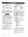
Vertical air com_essors must be bolted to the
floor. Bolting holliesare provided in the base feet.
Mount the air cqmpressor on a solid, level founda-
tion. Support c4mpressor weight evenly on a four
feet. Solid shims may be used if necessary.
• Lig $cralw
{nol sullied)
Torque to S-7 FLLb,
j Lag Scrow Ancho_ for ¢oncmtl
i (not =upplied)
Anchoring of Vertical Unit
Horizontal Un_
Some tank mour'ted compressor outfits are
shipped with (4) _bber isolator pads. When install-
ing compressor I
pad is to be pla¢
be smooth and li
square on all fou
supporL compre_
The horizontal ty
be bolted or lag{
'1Ltsworking location, one isolator
dunder each foot. The floor must
1el.The compressor should sit
feet. Install shims as needed to
;Sorweight evenly on all four feet.
_e compressor is not required to
ed to the floor.
(not supplied)
To_'que',o_T FLLa.
D20437 Rev. 0 2/15/00 8-ENG

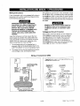
Wiring Instructions
If your compressor unit is not equipped with a plug-in
type power cord, perform electrical wiring according
to the following instructions:
IMPROPER ELECTRICAL GROUNDING
CAN RESULT IN A RISK OF ELECTRICAL
SHOCK. WIRING FOR THE PRESSURE
SWITCH AND ELECTRICAL MOTOR
SHOULD BE DONE BY A LICENSED ELEC-
TRICIAN IN ACCORDANCE WITH NA-
TIONAL AND LOCAL CODES AND ORDI-
NANCES,
Install the compressor outfit as close to the main
power supply as possible. This practice will avoid
using long lengths of e{ectrical wiring for the power
supply which can cause power Ioss_ the motor.
When connecting wires make sure that:
1. The amperage rating of the electrical box is
adequate, Refer to the Specification Chart in the
Outfit Parts Bulletin for your air compressor outfit.
2. The supply line has the same electrical character-
istics (voltage, cycle, and phase) as motor.
Wiring r_ust be such that full motor nameplate voltage
plus or_inus 10%, is available at the motor terminals
during s_arting.Refer to local codes for recommended
wire size_sfor correct wire size and maximum wire run;
undersiz_ wire causes high amp draw and overheating to
the motor,
Elea_rical wiring must be located away from
hot _lrfaces such as the compressor head,
carn_lressor cylinder, or compressor outlet
tube I
Voltag_ and Circuit Protection
Refer to _/ourOutfit Parts Bulletin for the voltage and
circuit pr_ection requirements of your compressor.
Use only]a fuse or circuit breaker that isthe same
rating as _he branch circuit the air compressor is
operatedlon, If the compressor is connected to a
circuit protected by fuses, use only dual element time
delay fuses, as noted in that Service Bulletin.
MAIN
FUSE
BOX
LIQUIDTITE FLEXIBLE
METAL CONDUIT WITH
GROUND LEAD
usE°
D_ONNEC_
swn'c_l OR ST_Q3_R W_H
Ct_Uff OVERLOAD m
I MOUN_ (r_ _QUIREO, _ _E
OUT_IT_Am_
___ MOTOR__ _ PRESSURE
SWITCH
Wiring of Compressor Units
with 80 Gallon Capacity
Wiring of Compressor U[nits
I
Typica_schbrnatic subject'to all changes asdictated by local
ele¢_i¢_!l codes and authorities.
i$ =usIO O,SCO_NI;CT
OR GIR&;UIT B_EA(ER
1
f IrT] ,
= L.... " ":..o_-.o I }
THFfE_ PH_ MAGNETIC
_O_O_ $Ta_lr WlTM
OVeR LO/_ pRO_3"ION
TO _aA_N s£RwC_
o_ c0_u_T _R_AK_R
1 c IL
[yPic_ _-wi_rlc 2
, I,
9-ENG D20437 Rev. 0 2/15/00

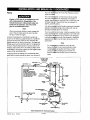
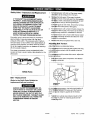
Piping
Plastic or PVC pipe is not designed for use
with compressed air. Regardless of its
indicated pressure rating, plastic pipe can
burst from air pressure. Use only metal
pipe for air distribution lines.
Note
Where a remote air intake is used, enlarge the
size of the air intake piping by one pipe size
for each 10 feet of length.
A typical compressed air distribution system as
shown on the following page should be of sufficient
pipe size to keep the pressure drop between the
supply and point of use to a minimum. All pipes and
fittings used must be certified safe for the pressures
involved. Pipe thread lubricant must be used on all
threads, and all joints are to be made up tight, since
small leaks in the piping system are the largest single
cause of high operating costs.
All piping should be sloped to an accessible drain
point and all outlets should be taken from the top of
DIRT LEG
\
the main
enter the
air line so that moisture cannot
The
than the corn
smaller line
100 feet long,
SCFM, use 3/_
It is recommer
between the a
distribution lin_
To remove dirt,
main distribLtti(
compressor to
ture before pa_
separators or ft
application.
air line should not be smaller
air discharge valve outlet. A
restrict the flow of air. If piping is over
:_rif required air flow will exceed 15
!i piping.
_ledthat a flexible coupling be installed
•discharge valve outlet and main air
to allow for vibration.
)il and water, install a separator in the
line. Install separator 5 to 6 feet from
IIIcw the air to cool to room tempera-
iing through the separator. Additional
ters may be used depending on the
Note
For underg_und installation, bury air lines
below the f_st fine and avoid pockets where
condensat|_n can gather and freeze. Apply
pressure b_]tore underground lines are cov-
ered to mal_e sure all pipe joints are free from
leaks.
FEEDER LINES
SLOPE WITH
AIR FLOW
AIR FLOW
_:_ AIR_LOW
[K ii
MAIN DISTRIBUTION AIR I I
AIR LINES USAGE
SlOpe pipe in direction of LEGS I]
air flaw. Watlr ¢¢md_ u
flaws _ bottom of Imipetal REGULATOR,
drlin legs,lxeventing it from ___ _A_N
mntmrlng fi_llr Iinm.
DRAIN
TRAP
DRAIN
TRAPS
DIRT LEG
AIR COMPRESSOR
MOISTURE SEPARATOR
AND TRAP
/
U
FLEXIBLE
COUPLING
AI R DISCHARGE
VALVE
DRAINCOCK
VALVE
D20437 Rev. 0 2/15/00
Typl©ld Camprolmed Air Distribution System
10-ENG

Additional Regulators and Controls
Since the air tank pressure is usually greater than that
which is needed, a separate regulator is usually
employed to control the air pressure ahead of any
individual air driven device.
Separate air transformers that combine the functions
of air regulation and moisture and dirt removal should
be used where applicable.
Lubrication and Oil
Compressors are shipped without oil. Do
not attempt to operate in order to check
wiring or for any reason without first
adding oil to the crankcase. Serious
damage to the pump can result from even
very limited use without oil. Fill crankcase
with recommended oil before=operating,
Remove the oil fill plug and fill the crankcase with
recommended oil. See page 15 in this manual for the
specific oil recommended for use in your compressor
unit. When filling the crankcase the oil flows in very
slowly. If oil is added too quickly, it will overflow and
appear full. Replace the oil fill plug.
Break-In Procedures
Serious damage may result if the following
break-in instructions are not closely
followed.
This required only once, before the air
corn put into service.
1. R¢ciieck compressor wiring. Make sure wires are
sec_lt!,eat all terminal connections. Free all con-
tab1 iiof loose wire cuttings, etc.
2. Pe8 on the fuse disconnect orcircuit breakerto
th_ CN position and, if equ pped, turn the ON/
AUTt i OFF switch on the pressure switch to the
ON pasition.
i
3. Ope 8 the air outlet valve fully to permit air to
es#a_e and prevent air pressure build-up in the
tank _uring the break-in period.
4. Rdn 'the compressor for 30 minutes. Make sure
th_ alt'outlet, or globe valve, is open and there is
noita_lk pressure build-up.
5. CI_C_ all air line fittings and connections/piping
fori aiHeaks by applying a soap solution. Correct
as i_ssary. Even minor leaks can cause this air
coml_essor to overwork, resulting in premature
break_down or inadequate performance.
6. Chsc_for excessive vibration and noise. Adjust air
coml_mssor belt guard as necessary to eliminate
ch_t _Re-adjust or shim the air compressor feet,
if nleq ,sary, for proper level.
L
7. CIQs he outlet valve and let air compressor
pul_p jp to "cut-out pressure". Turn the air
comp Sssor off and check oil level. Add oil if
neqe_ _ary. Connect air hose to air outlet adapter.
Your c0m_ressor is now ready for use.
11-ENG D20437 Rev. 0 2/15/00

,
,
.
.
Before attaching an air hose or accessory, make
sure the outlet valve is in the closed position. On
units equipped with a pressure switch lever make
sure the switch is in the OFF position.
Compressed air from the outfit may contain
water condensation and oil mist. Do not
spray unfiltered air at an item that could be
damaged. Some air operated tools or
devices may require filtered air. Read
instructions for air tool or device.
Attach regulator, hose and accessory. On models
without an air pressure regulator, one must be
installed before using accessories rated at less
than 125 psig.
Too much air pressure causes a hazardous
risk of bursting. Check the manufacturer's
maximum pressure rating for air tools and
accessories. The regulator outlet pressure
must never exceed the maximum pressure
rating.
Tum the compressor on and allow tank pressure
to build. On units equipped with a pressure switch
lever, place the switch in the ON-AUTO position.
The motor will stop when tank pressure reaches
"cut-out pressure".
Open the outlet valve.
ON/AUTO-OFF
SWfTCH {NOT ON
ALL PRESSURE PRESSURE
SWITCHES) _ SWITCH
5. If an air pres
regulator by
regulator 1o1
outfit is read
.',,e.You,,r,
!
I
6. Turn the .'1o
C'rl
r_gl
7. Turn the
]ure regulator is in use, open the
Jming it clockwise. Adjust the
e correct pressure setting. Your
for use.
_ished:
ipressor unit off.
/;
iiator counterclockwise and set the
outlet pre_sL _ to zero.
8. Remove tt_e _!r tool or accessory.
9. Open the ie_lj_ator and allow the air to slowly
bleed from tl_petank. Close the regulator when tank
pressure iS _roximately 20 psi.
10. Drain air tank.
11.
WATER
TANK. IF I
CORROD!
CAUSING
THE AIR
ERLY.
ONDENSE IN THE AIR
'DRAINED, THE WATER WILL
ID WEAKEN THE AIR TANK,
TANK RUPTURE.
MUST BE DRAINED PROP-
After the water has been drained, close the drain
cock.
- if the cornpr
at least on._e
- if the corrlpf
drain after ba
Operate the i,
drain cocki C
tainer. Contir!
removed frbn
tightly.
#ssor is under continuous use - drain
_ch day.
_ssor is only used occasionally -
use.
_it to apply 15-20 psig and open the
_!lect the water in a suitable con-
_ieoperating unit until all moisture is
li_e air tank. Close the drain cock
Note
If drain coclk _81ve is clogged, release air
pressure ini ai_itank. The drain cock valve can
then be remo_ed, cleaned and reinstalled.
D20437 Rev. 0 2/15/00 12-ENG

UNIT CYCLES AUTOMATICALLY WHEN __iNG MAINTENANCE, YOU COULD BE
POSEOTOVOLTAQESOURCES. PA.TS.PERSONAL,NJUR,ES
h ii ,
To ensure efficient operation and longer life of the air compressor" oQtfit, a routine maintenance schedule should
be prepared and followed. The following routine maintenance sch_ble is geared to an outfit in a normal work-
ing environment operating on a daily basis. If necessary, the sche_ul_ should be modified to suit the conditions
under which your compressor is used. The modifications will dep_n_ upon the hours of operation and the
working environment. Compressor outfits in an extremely dirty an_l/6f hostile environment will require a greater
frequency of all maintenance checks. Lubricate compressor motdr _cording to manufacturer's instructions,
which are attached to your motor.
A clean air compressor runs cooler and provides longer service, qle_n or blow off fins and any other parts of
the air compressor that collect dust or dirt. Do not place rags, cor_taln_ersor other material on or against the
ventilation openings in the belt guard. Adequate ventilation is neces_lry to maintain proper air compressor
operating temperature. =
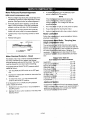
Routine Maintenance Schedule
Every 8 Hours of Operation
Overfilling with oil will cause premature compres-
sor failure. Do not overfill.
1. Check oil level. Add ifnecessary.
2. Drain water from the air tank, any moisture sepa-
rators or transformers.
3. Check for any unusual noise and/or vibration.
4. Manually check all safety valves to make sure they
are operating properly.
5. Inspect for oil leaks and repair any leaks found.
Every 40 Hours of Operation
(Single & 2 Stage Compressors)
1. Clean and inspect the air intake filter; replace if
necessary.
2. Inspect condition of drive belt; replace if neces-
sary.
First 100 Hours of Operation
(Single & 2 Stage Compressors)
1. Drain and refill compressor crankcase with clean
oil. Refer to Service instructions for recommended
oils.
2. Increase frequency of oil changes if humidity or
operating conditions are extreme.
Every rl_ Hours of Operation (Single Stage)
1. Drbinl'and refill compressor crankcase with 16 fluid
ounc_ (473.2ml) of clean oil, SAE-20W-20 SG.
(USe_E 10W oil under winter-type conditions.)
2. Inqre_Se frequency of oil changes if humidity or
oper_ ling conditions are extreme.
Every 16/ Hours of Operation
(Single_& iStage Compressors)
1. Ch_e¢ :lrive belt tension adjust if necessary. (See
page 15.)
2. InspE :air lines and fittings for leaks; correct as
nece, isary.
3. Ch_ci _the a_ignment of the motor pulley to the
flYWh_el. If necessary, align to within 1/32 inch on
ce_te line.
Every 501i Hours of Operation
(2 stage :,ompressor units)
1. Drain and refill compressor crankcase _vith_cTe&n
oil. S,ie page 14 for recommended oils.
2. Incre=!se frequency of oil changes if humidity or
operl _lng conditions are extreme.
Each Ye_ it of Operation {2000 Hours) or ff a Prob-
lem is Sa _pected
(Single & 2 Stage Compressors)
Check condition of air compressor pump intake and
exhaust v_ilves.Replace if damaged or worn out.
(Refer to ;l_heOutfit Parts Bulletin.)
13-ENG D20_37 Rev. 0 2/15/00

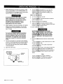
Air Filter - Inspection and Replacement
NOTE
Keep the air filter clean at all times. Do not
operate the compressor with the air filter
removed.
A dirty air filter will not allow the compressor
to operate at full capacity, Before you use the
compressor, check the air filter to be sure it is
clean.
If it isdirty, replace it with a new filter. On some
models, the filter may be removed by using a pair of
needle nosed pliers or a screwdriver. Pull or pry out
the old filter. Push in the new air filter. Other models
require removal of the belt guard and/or filter retainer.
Oil - Checking and Changing
Overfilling with oil will cause premature
compressor failure. Do not overfill.
1. Check oil level in compressor crankcase before
each use. The oil level should be to the middle of
the oilsight glass. On compressors without a sight
glass the oil levelmust not be allowed to be lower
than 3/8" from the top (6 threads) at any time.
2. Replace the oil after:
Two Stage - 500 hours of operation. (Replace oil
after initial 100 hours of operation.)
3. Remove the oilfill and drain plugs. Collect the oil
in a suitable container.
4. Replace the oil drain plug and refill the crankcase
with recommended oil. When filling the crankcase
the oil flows in very slowly. If oil is added too
quickly, it will overflow and appear full.
NOTE
It is important to maintain the proper oil level.
A low oil level reduces proper cylinder wall
lubrication and increases ring wear.
5. Replace the oil fill plug.
6. Start the compressor outfit and run for several
minutes. Shut the compressor down and check
the oil level. If necessary, add more oil.
Two Sta
)ressor Units
!
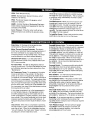
Viscosity Chart
Recomme_lde,€l Oil
(API SG/C 0
Heavy Duty) ....
SAE 20
SAE 40
i li,,
Room or
Ambient
Temperature
Below 20oF
Above 32oF
Crankcase caPa_lltY equals (approximately) 42 fluid
ounces.
Check Val_ Inspection and Replacement
Removeandi s ,otthecheckvalveatleastoncea
year or more _ if the compressor is heavily used.
Moisture and _)tl_r contaminants inthe hot com-
pressed air will c_Use an accumulation of a carbon-
like residue or_tl_ working parts. Ifthe valve has
heavycarbon oll -up,shouldbereplacedUsethe
following procedure to inspect, clean or replace the
check valve.
1. Turn corn disconnect or lock out
2. Release ai
3. Loosen
the outlet
4. Unscrew
usin(
the air tank.
and bottom tube nuts and remove
leck valve (turn counterclockwise)
CHECK
TANK
5. Check that]t_ valve d sc moves freely and that
the spring I_ol_lSthe disc in the upper, closed
position. T_,e _heck valve may be cleaned with a
solvent.
6. Apply seal_n[l_o _he check valve threads. Reinstall
the check yal_ (turn clockwise). Do not over-
tighten.
7. Replace the e_let tube and tighten top and
bottom nut_. :
D20437 Rev. 0 2/15/00 14-ENG

Safety Valve - Inspection and Replacement
IF THE SAFETY VALVE DOES NOT WORK
PROPERLY, OVER-PRESSURIZATION MAY
OCCUR, CAUSING AIR TANK RUPTURE OR
EXPLOSION. OCCASIONALLY PULL THE
RING ON THE SAFETY VALVE TO MAKE
SURE THAT THE SAFETY VALVE OPER-
ATES FREELY. IF THE VALVE IS STUCK OR
DOES NOT OPERATE SMOOTHLY, IT
MUST BE REPLACED WITH A VALVE
HAVING THE SAME PRESSURE RATING.
The safety valve is set at the factory to a pressure
approximately 15 pounds higher than the rated
pressure of the outfit. If the pressure switch malfunc-
tions and does not shut off the motor automatically at
maximum tank pressure, the safety valve will protect
the air tank against excessive air pre_sure by popping
off at its preset pressure.
Two stage compressor pumps equipped with after-
coolers will have a second safety valve installed on the
aftercooler.
Safety Valve
Belt- Replacement
(Refer to the Outfit Parts Bulletin for
replacement belt part number.)
SERIOUS INJURY OR DAMAGE MAY OC-
CUR IF PARTS OF THE BODY OR LOOSE
ITEMS GET CAUGHT IN MOVING PARTS.
NEVER OPERATE THE OUTFIT WITH THE
BELT GUARD REMOVED. THE BELT GUARD
SHOULD BE REMOVED ONLY WHEN THE
COMPRESSOR POWER IS DISCON-
NECTED.
.
T_rn
and
l
the.,
_ompressor off, lock out the power supply,
_lieveall air pressure from the tank.
ve the belt guard. If the guard is plastic,
the front of the belt guard by disengaging
tps. Insert a flat bladed screwdriver at each
>cation and pry the belt guard apart.
If _he_i_eltguard is wire mesh remove four screws,
four _iiPS and outer panel of belt guard.
3. F_ _0mpressors with a motor tilt plate, loosen the
wi#g _ut at the tilt plate. The motor can be tilted to
all_for easy removal or installation of the belt.
Fo_"€_mpressors with a motor slide mount, oosen
the r_0tor mounting hardware and slide the motor ....
to_aI_ the compressor.
4. Re_e the belt and replace with a new one.
AdjuStil !g Belt Tension
Adjust be i tension as described below.
For corin_ _ssors with motor tilt plate, tighten the wing
nut until il _akes contact with the washer, plus one
additiona i_rn.
For co_10_essors with a motor slide mount adjust belt
teosior a fo,ows:
1. Slide _otor away from compressor until desired
tentic_._,,s obtained.
DRIVE BELT
DOWNWARD FORCE
MIDWAY
DEFLECTION
MOTOR
PULLEY
On two is e comoressors, the belt should deflect 3/
16" at _id_ay between the pulley and the flywheel
when a 5 _ound weight is applied at the midway
point.
2. Tigllte_l two outside cap screws enough to hold
the m_tor in place for checking pulley and fly-
wheel_lignment.
15-ENG D20437 Rev. 0 2/15/00

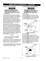
Motor Pulley and Flywheel Alignment
(slide mount compressors only)
1. Place a straight edge along the outside face of the
compressor flywheel to check alignment of V-belt
grooves. (See figure below for proper alignment.)
2. If the belt grooves aren't aligned, continue with
step 3 of this procedure. If the belt grooves are
aligned, continue with step 4 of this procedure.
3. Loosen motor mounting screws and move the
motor until motor pulley is in proper alignment.
4. Tighten all four motor mounting screws to 10-20
ft-lbs.
5. Reinstall belt guard.
V-BELT MOTOR PULLEY
_L_
STRAIGHT
AI _ #,-2(MEASURE01 EDGE
B1 = B2 (VISUALI
Motor Overload Protector - Reset
The electric motor has a thermal overload protector. If
the motor overheats for any reason, the thermal
overload protector willshut off the motor. The motor
must be allowed to cool down before restarting.
If equipped with an ON/AUTO-OFF pressure switch,
restart as follows:
1. Tum the ON/AUTO-OFF switch to the OFF posi-
tion.
2. Depress the reset button located on the end of the
electrical motor.
3. To restart the motor, turn the ON/AUTO-OFF
switch to the ON/AUTO position.
If not equipped with an ON/AUTO-OFF pressure
switch, restart as follows:
1. Position the fuse disconnect or circuit breaker to
the OFF position.
2. Depress the resuL button located on the end of the
electrical motor.
3. TO restar .turn the ON/AUTO-OFF
switch to 1 _N/AUTO position.
NOTE
If the tha
motor off 1
voltage pr
su,€
1. The mo
2. Fuses
3. Lights dim
Motor Lui
Follow the n-
attached to,
Corn
stage
The corn
torqued.
first five hours
the
necessary.
compressor
saP/.
protector shuts the
check for possible
Low voltage can also be
not get up to full power or speed.
starting the motor.
remain dim when motor is started.
on
_mendations that are
=ad Bolts - Torquing (two
;ors only)
should be kept properly
torques of the head bolts after the
and compare the values to
table below. Retighten if
are also shown for other
_rsshould disassembly be neces-
|TOrque Valve Table for
Bare G;ol_pressor_"Metric Fasteners
Head Bolts ...._'_"*ti:i................................. :.20
Frame to CylinderliBolts ............................ 25
Bearing End C_v_' ................................. 5
Aftercooler Bo_S_lil ................................... 20
Filter
Support E_. .................................
20
Crankcase Base 8_6rews .......................... 20
Oi Dra n Plug 4...LL... ................................ 5
Oil Sight Glass
Rod Bearing Sc
Intercooler Scr{
Flywheel Bolt ..
Additional S
Disassembly or
what is coverec
additional servi
Authorized Wa_
ft-lb
ft-lb
ftqb
ft-lb
ft-lb
in-lb
ft-lb
.... 10 in-lb
_..:l!i_..................................
r_s ................................ 25 ft-lb
..................................2oft-lb
""I_"................................... 20 ft-lb
i
s_ice of the air compressor beyond
Iil_'i_is manual is not recommended. If
_eJt_required, contact your nearest
ral_ty Service Center.
D20437 Rev. 0 2/15/00
16-ENG

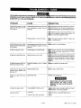
;E F_'._ORNAMILNINGjFIE_¢IlvlR_yMA_EXF_OpS_2___ATTEMPTING AI_I'_I_PPA_T_uONRpCL UO_;_EScSEDAIF:II_OURCAENSD
BLEED OFF ALL TANK AIR PRESSURE.
PROBLEM
Excessivetank pressure- safety
valve pops off (units with ON-
AUTO switch)
Excessivetank pressure -safety
valve pops off (unitswithout ON-
AUTO switch).
Air leaks at fittings or hose.
Airleaks at or inside check valve.
Air leaks at pressure switch re-
lease valve during running.
Continuous air relieving from
pressure switch release valve
after shut off.
Air leaks in air tank or at air tank
welds.
Air leak from safety valves.
Squealing sound.
CAUSE
Pressure switch does not shut off motor
when compressor reaches "cut-out"
pressure.
Pressure switch "cut-out" too high.
Pressure switchdoes not shut off motor
when compressor reaches "cut-out
pressure".
Tube fittings are not tight enough.
i ....
Defective or dirty check valve.
Defective pressure switch release
valve.
Defective check valve.
Defective air tank.
Possible defect in safety valves.
Loose belt.
There is no oil in the compressor.
i,ii
_i_
M_ve the pressure switch [everto the "OFF" position.
Ifl_4theoutfit doesn't shut off, and the electrica con-
_ arewelded together, replace the pressure switch.
If_e contacts are good, check to see ifthe pin in the
I_om of the pressure release valve is stuck. If it
_s not move freely, replace the valve.
R_Um the outfit to Service Center to check and
a_t_st, or replace switch.
, iili_iI
P_sure switch must be replaced.
"_en fittings where air can be heard escaping.
;_Fk fittings with soapy water solution, DO NOT
)_RTIGHTEN.
_d_ective check valve results in a constant air leak
t _1_epressure release valve when there is pressure
1l_e tank and the compressor is shut off. Remove
_iclean or replace check valve. DO NOT OVER-
,,!,,ii=!i'i,
le_#ve and replace the release valve.
i_l'A r Leak at Check Valve."
I
_Jf'_nk must be rep,aced.
iDO NOT DRILL INTO, WELD, OR OTHER-
WISE MODIFY AIR TANK. IT WILL
IWEAKEN. THE TANK CAN RUPTURE OR
I .ii_ XPLODE"
! i
_p_mte safety valves manually by pulling on ring. Ifa
yal_ still leaks, it should be replaced.
,_dj_t belt tension. (See Belt Replacement.)
17-ENG D20437 Rev. 0 2/15/00

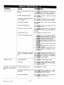
PROBLEM CAUSE
Motor will not run.
Excessive belt wear.
Compressor is not supplying
enough air to operate accesso-
ries.
Motor overload protection switch has
tripped.
Possible defective capacitor.
Tank pressure exceeds pressure switch
"cut-in pressure".
Check valve stuck open.
Loose electrical connections.
Paint spray on internal motor parts.
Possible defective motor.
off and reset switch by pressing the
on the end of the motor. If the
trips, check for defective capacitor.
Center for inspection or replace-
Motor Wilt i_lart automatically when tank pressure
drops b _itO_!"cut-in pressure" of pressure sw tch
Remov_allld clean or replace. DO NOT OVER-
TIGHTEI.
Check v_Iraqi connection inside pressure switch and
motor t_ nlr_l_al box area.
Have chI,(_l_d at Service Center. Do not operate the
compret S_l.fn the spray area. See Flammable Vapor
Warnin_
Have c_cl4_d at a local Service Center.
Fuse blown, circuit breaker tripped. 1. Checkl_l
necesBai
fusel0_._l
sper41Ifl_(
2• Cheekl_
deta_ f_
dela_ f_
3. Chel¢k Ifi_
exte_8ial
4. Re_t_
stuck ¢_
5. Disci0nrt_
cJroullt QI
brartehl_
Jse box for blown fuse and replace if
y. Reset circuit breaker. Do not use a
"cuit breaker with higher rating than that
for your particular branch circuit.
_r proper fuse; only dual element time
es are acceptable. Use a Type "T" time
e.
,r low voltage conditions and/or proper
I cord.
check valve and clean or replace if it is
_n or closed•
_ct the other electrical appliances from
operate the compressor on its own
rcuit.
Pressure release valve on pressure
switch has not unloaded head pres-
sure.
Loose belt/tight belt.
Loose pulley.
Prolonged excessive use of air.
Compressor is not large enough for air
requirement.
Restricted air intake filter.
On an qr¢_ pressure switch equipped with a
pressur_ r_t!_f valve, bleed the line by pushing the
pressur_4 _iIch to the OFF position. If valve does not
open b¢1_ t_he lever until it does. If valve still fails to
bleed, r_pl_e the valve assembly.
! ill
Adjust b_lt _nsion. (See Belt Replacement.)
i ii
'i
Check fq_ _m keyway or pulley bore. Also check for
bent moCk, haft. Replace parts if necessary. (Refer
to the o_lr_ 'Parts Bulletin.)
Decreas_ a_bunt of air usage.
Check t i.e _gcessory air requirement. If it is higher
than the _ _ or pressure supplied by your air com-
pressor, y_ _'need a larger compressor.
li
Clean ol irql ce air intake filter. Do not operate the
compre_ _ _l_nthe paint spray area.
i:
D20437 Rev. 0 2/15/00 18-ENG

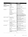
PROBLEM
Compressor is not supplying
enough air to operate accesso-
ries, (Continued)
Knocking noise.
Excessive oil consumption.
Compressor overheating.
Motor overheating.
CAUSE
Loose belt,
Hole in hose.
Check valve restricted.
Air leaks.
Defective check valve.
Loose pulley.
Low oil level.
Loose flywheel.
Loose compressor mounting screws.
Belt too tight/too loose.
CarbOn build-up,
Restricted air intake,
Compressor overworked.
Poor quality oil.
The compressor is overworked.
The aftercooler tube and/or check valve
is restricted.
Dirty compressor.
High ambient temperature.
Incorrect oil. low oil.
Compressor starting against load.
Low voltage.
Pressure switch set beyond factory
setting.
Belt too tight.
Compressor valves have excessive
carbon deposits build-up; restricted
check valve.
;)N
tension.
replace if required.
clean or replace.
hten fittings. (See "Air Leaks" section of "Trou-
)
and clean or replace.
Ihten pulley set screw, 70-80 in-lb.
prescribed oil level. Add oil.
hten screw, 15 to 20 ft-lb.
_eck screws, Tighten as required.
ill!
ust belt tension, (See Belt Replacement.)
and valve plate. Clean the valve
)p of the piston. (Be sure carbon does
fall into the cylinder.) Reassemble using new
_kets and torque screws, 25 to 30 ft-lb.
',ethe air intake.
:tuce air consumption or add another air com-
take up some of the load.
pump and replace with correct oil. Refer to
and Oil Section.
air consumption or add another air com-
take up some of the load.
check valve. Clean if neces-
pressor thoroughly.
remote air intake.
oil recommendation on page 14.
pressure switch. Replace with correct
e. Consult local power com-
, or electrician.
)r which outfit
designed as noted on nameplate.
A_iust for proper tension.
: I;L
Gl_ln or replace compressor valves or
check valve,
19-ENG D20437 Rev. 0 2/15/00

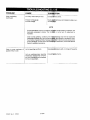
PROBLEM
Motor overheating.
(Continued)
Water in pump crankcase; oil
appears milky in color.
CAUSE
Too many motor starts per hour.
Improper wiring gauge.
Incorrect voltage.
Center.
Check _leC_rical hookup and installation data or con-
suit
NOT_
Current style electric motors runrelatively hol_i_r normal operating conditions, with
reasonable compressor loading. This cond_iitib_ is normal and no adjustment is
necessary.
Under normal operating conditions, the mq_l_mperage draw will not exceed the
nameplate amperage rating, plus the service f_', as it appears on the electric motor.
Ifa condition of Sustained high amperage exi_l_efer to service checks above and/or
consult electrician. If cause cannot be isolat_l I_ an electrician, consult with Service
Center for additional assistance.
Humid operating conditions.
Unit not reaching proper operating
temperature because the compres-
sor runs infrequently and isoversized
for the air requirement.
]b i ,_ilil
Re ocate a_ll3ressor outfit, or change oil frequently.
Consult _Nice Center.
D20437 Rev. 0 2/15/00 20-ENG
Page is loading ...
Page is loading ...
Page is loading ...
Page is loading ...
-
 1
1
-
 2
2
-
 3
3
-
 4
4
-
 5
5
-
 6
6
-
 7
7
-
 8
8
-
 9
9
-
 10
10
-
 11
11
-
 12
12
-
 13
13
-
 14
14
-
 15
15
-
 16
16
-
 17
17
-
 18
18
-
 19
19
-
 20
20
-
 21
21
-
 22
22
-
 23
23
-
 24
24


Craftsman 919.167800 Owner's manual
- Category
- Air compressors
- Type
- Owner's manual
Ask a question and I''ll find the answer in the document
Finding information in a document is now easier with AI
Related papers
-
Craftsman 919.724321 User manual
-
-
-
-
Craftsman 919.167312 Owner's manual
-
-
-
-
-
Other documents
-
 DeVilbiss Air Power Company D23757 User manual
-
Delta A08184 User manual
-
Porter-Cable CPF6025VP User manual
-
Encore electronic (66-501-1) User manual
-
Makita MAC2400 User manual
-
-
 John Deere AC2-80ES User manual
-
Black & Decker C7501M User manual
-
 Excell Precision E7540 User manual
-
DeVillbiss Air Power Company LM7580V2C User manual


