Unbranded Q6SE Installation guide

Type
Installation guide
HEATER KIT INSTALLATION INSTRUCTIONS
IMPORTANT
ATTENTION INSTALLERS:
These instructions are primarily intended to assist qualified individuals experienced in the proper
installation of this appliance. Some local codes require licensed installation/service personnel
for this type of equipment. All installations must be in accordance with these instructions and
with all applicable national and local codes and standards.
Please read all instructions carefully before starting the installation. Return these instructions
to the customer’s package for future reference.
DO NOT DESTROY. PLEASE READ CAREFULLY AND KEEP IN A SAFE PLACE FOR FUTURE REFERENCE.
NOTE: Model H9HK035Q-21 shown.
H9HK SERIES HEATER KITS FOR INSTALLATION IN 208/240V AND 480V
LIGHT COMMERCIAL PACKAGED AIR CONDITIONERS
Revision: CP-H9HK (05-20) 1012566-B
Supersedes: CP-H9HK (08-19) PN1012566R1
TABLE OF CONTENTS
IMPORTANT SAFETY INFORMATION .........................2
GENERAL INFORMATION ............................................ 2
Clearances to Combustibles ...........................................3
Wiring Diagrams .............................................................. 3
Clearances ......................................................................3
ELECTRICAL SUPPLY .................................................. 3
Installation Preparations .................................................3
Terminal Blocks ...............................................................3
Circuit Options .................................................................3
Single Branch Circuit Electrical Connection ..................3
Multiple Branch Circuit Electrical Connection ................ 3
Circuit Breakers ............................................................... 3
Breaker Removal ...........................................................4
HEAT KIT INSTALLATION .............................................4
AIRFLOW .......................................................................6
FIGURES AND TABLES ................................................6
Table 3. Heater Kit Model Cross Reference ................... 6
Electrical Data .................................................................7
Table 4. MCA/MOP Data (Single Circuit) .......................7
Table 5. MCA/MOP Data (Multiple Circuit).....................8
Electrical Diagrams .........................................................9
Figure 13. Single and Dual Power Supply Connections 9
Figure 14. Wiring Diagram for 9 kW, 240V, 3-Phase ......10
Figure 15. Wiring Diagram for 9 kW, 480V, 3-Phase ......11
Figure 16. Wiring Diagram for 18 kW, 240V, 3-Phase ....13
Figure 17. Wiring Diagram for 18 kW, 480V, 3-Phase ....14
Figure 18. Wiring Diagram for 30 and 35 kW,
240V, 3-Phase ............................................................16
Figure 19. Wiring Diagram for 30 and 35 kW,
480V, 3-Phase ............................................................17
IMPORTANT SAFETY INFORMATION
INSTALLER: Please read all instructions before servicing
this equipment. Pay attention to all safety warnings and
any other special notes highlighted in the manual. Safety
markings are used frequently throughout this manual to
designate a degree or level of seriousness and should not
be ignored. WARNING indicates a potentially hazardous
situation that if not avoided, could result in personal injury or
death. CAUTION indicates a potentially hazardous situation
that if not avoided, may result in minor or moderate injury or
property damage.
WARNING:
RISK OF ELECTRICAL SHOCK
Shut off all electrical power to the unit before
performing any maintenance or service on the system.
Failure to follow this warning can cause serious injury,
fire, electrical shock, or death.
The installer performing this work assumes all responsibility
when installing this kit. These instructions are primarily
intended to assist qualified individuals experienced in the
proper installation of these components. Some local codes
may require licensed installation/service personnel for this
type of equipment. Safety should always be the deciding
factor when installing this product and using common sense
plays an important role as well. Improper installation of
the components or failure to follow safety warnings could
result in serious injury, death, or property damage.
Unless noted otherwise in these instructions, only factory
authorized parts or accessory kits may be used with this
product. Improper installation, service, adjustment, or
maintenance may cause fire, electrical shock or other
hazardous conditions which may result in personal injury
or property damage.
Please read all instructions carefully before starting the
installation. If a problem occurs, check the instructions
and follow recommendations given.
The information shown in these instructions must be
followed during the installation of this kit. Unqualified
individuals should not attempt to interpret these instructions
or install this equipment. If you do not possess mechanical
skills or tools, call your local dealer for assistance.
Use caution when handling the appliance or removing
components. Personal injury can occur from sharp metal
edges present in all sheet metal constructed equipment.
GENERAL INFORMATION
H9HK heater kits are approved for use in P7TQ packaged air
conditioners when applied and installed according to these
instructions. Use the model identification code in Figure 1
and Table 1 for approved H9HK heat kit applications in air
conditioner systems. Refer to the National Electric Code
(ANSI/NFPA 70) or in Canada the Canadian Electric Code
Part 1 (CSA C.22.1) and applicable local codes for overcurrent
H9HK 009 -H 0 1
Heater
Heater Kit
9 = (P,Q)7TQ
Electric Heater
009 - 9KW
018 - 18 KW
030 - 30 KW
035 - 35KW
No. of Breakers
Electric Code
N = 575-3-60
Q = 208/240-3-60
S = 480-3-60
Stage
s
Figure 1. Heater Kit Identification Code
2
CP-H9HK (05-20) 1012566-B
Approved H9HK heater kits are shipped ready to install using
single or dual circuit electrical supply and existing factory
installed terminal blocks. If dual circuit supply is desired,
follow instructions included under Multiple Branch Circuit
Electrical Connections section.
NOTE: Use of the 3 pole terminal block found in the main
control panel is for the unit's refrigerant cooling circuit only.
This circuit includes:
• Compressors
Blower motors
OD fan motors
Low Voltage transformer (all unit electrical loads)
Circuit Options
P7TQ units installed with electric heat may be wired for single
or multiple circuit supply connections.
Single Branch Circuit Electrical Connection
Units are factory ready for addition of H9HK heater kits. See
unit rating label or Table 4 (page 7) for single point power
circuit Minimum Circuit Ampacity (MCA) and Maximum Over-
Current Protection of branch circuit wiring.
Field wiring will be routed from the branch circuit disconnect
to this 3 pole terminal block for both heating and cooling
operation.
Multiple Branch Circuit Electrical Connection
For Dual Point Power Circuit connections see the unit rating
plate or electrical data in Table 5 (page 8) for proper high
voltage branch circuit requirements. Both 3 pole terminal
blocks provided in the unit will be used for converting to dual
supply connections.
The 3 pole terminal block located in the electric heat vestibule
is for connection of the electric heater kit branch circuit wiring.
Field wiring will be routed from the electric heat branch circuit
disconnect to this 3 pole terminal block for heating operation.
The factory supplied red, yellow, and black wires connected
to the electric heat terminal block from the main unit 3 pole
terminal block must be removed. These 3 wires (if long enough)
may be used for connection between the unit main control
panel 3 pole terminal block and the second branch circuit
power supply disconnect for cooling and blower operation.
See Figure 13 (page 9).
Circuit Breakers
If circuit breakers are used for any circuit, they must be
used for all electric heat circuits. Use one breaker for each
circuit. See Table 3, (page 6). If circuit breakers are not
being used, proceed to the Heat Kit Installation section on
page 4.
IMPORTANT NOTE:
Circuit breakers (if installed) in the unit with the addition
of heater kits are for short circuit protection of the internal
heater element circuit wiring and DO NOT serve as a
unit disconnect. The circuit breakers DO NOT provide
over-current protection of the supply wiring.
Whether or not circuit breakers are used in the units,
protection and disconnect requirements. NOTE: If any of
the original wiring supplied with the unit must be replaced,
it must be replaced with material of the same gauge and
temperature rating.
Clearances to Combustibles
All units are approved for zero clearance to combustibles when
installed according to these instructions and other instructions
included with the unit and other approved accessories.
Wiring Diagrams
Wiring Diagrams are shipped with each H9HK heater kit
assembly. Attach the heater kit wiring diagram label over the
bottom half of Sheet #2 of the unit wiring diagram label on
the control panel access door. For proper adherence, make
sure the surface is clean and free of oil before applying.
Clearances
All H9HK electric heater kits are approved for use in
installations with zero-clearance to combustibles at any blower
speed allowed on the units blower performance charts for
both Horizontal and Downflow applications when installed
according to these instructions and other instructions included
with the unit and other approved accessories. See note (in
bold type) for vertical duct applications in Heat Kit Installation
section on page 4.
ELECTRICAL SUPPLY
All wiring must comply with the current revision of the National
Electric Code and must be sized for the minimum ampacities
as listed on the unit data label or in Table 1. Refer to the
detailed wiring diagrams for proper connections: Figure 13,
Figure 14, Figure 15, Figure 16, Figure 17, Figure 18, and
Figure 19.
If the unit was previously installed without electric heat, the
existing supply wiring may not be sufficient to handle the
increased load. See the unit rating label or Table 4 (page
7) or Table 5 (page 8) for minimum circuit ampacities
and maximum overcurrent protection ratings.
Installation Preparations
Before proceeding with the electrical connections, make sure
that the voltage, frequency, and phase of the supply source
are the same as those specified on the unit rating label. Also
verify that the service provided by the utility is sufficient to
handle the additional load imposed by this equipment.
Terminal Blocks
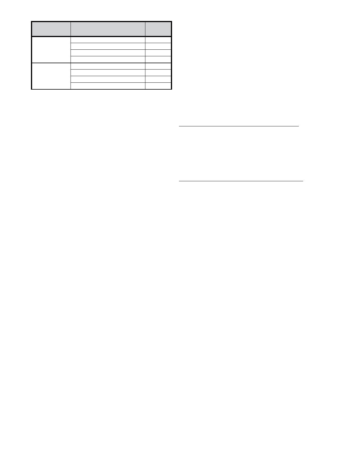
Table 1. Heater Kits and Part Numbers
HEATER
KITS
DESCRIPTION
PART
NUMBER
3 PHASE
208/240V
H9HK009Q-01 (9kw) 1011669
H9HK018Q-11 (18kw) 1011672
H9HK030Q-21 (30kw) 1011675
H9HK035Q-21 (35kw) 1011678
3 PHASE
480V
H9HK009S-01 (9kw) 1011670
H9HK018S-01 (18kw) 1011673
H9HK030S-01 (30kw) 1011676
H9HK035S-01 (35kw) 1011679
3
CP-H9HK (05-20) 1012566-B
overcurrent protection of the unit supply wire must be
provided at the branch circuit distribution panel and must
be sized as shown in Table 3, (page 6) or on the unit
rating label and according to the National Electric Code,
Canadian Electrical Code and applicable local codes.
NOTE: In most cases the overcurrent protection specified
on the unit rating label is less than the 60 amp rating of
the circuit breakers used in the units. This is because
the function of the overcurrent protection required at the
distribution panel (field supplied) and the unit mounted
breakers is different.
Breaker Removal
Insert a screwdriver into the hole (in the white release tab)
and pull down. NOTE: The white release tab is located at
the base of the breaker under the line side (right) terminals.
HEAT KIT INSTALLATION
Rooftop installations with vertical ducts must be provided
with a 90-degree elbow installed in the supply duct to
comply with U. L. (Underwriters Laboratories) codes for
use with electric heat so the elements are not directly
over a supply grille.
1. Remove Compressor Access panel. See Figure 2.
foam wire guards for later use. See .
4. Install the DIN rail mounting bracket inside of the
unit and tightly secure it with two screws. See .
NOTE: This step needs to be performed only if circuit
breakers are included with your kit.
5. Mount circuit breakers (if included with your kit) onto the
Figure 2. Compressor Access Panel
Figure 3. Electric Heat Kit Access Panel
2. Remove electric heat vestibule cover by pulling straight
out, perpendicular to the unit. See .
3. Remove electric heat access plate. Retain all screws and
Figure 6. Single Circuit Breaker and Contactor
Figure 5. DIN Rail Location
Figure 4. Electric Heat Access Plate
DIN rail. NOTE: Secure circuit breaker(s) to bracket by
hooking the rear top groove over the din rail and pushing
in on the bottom until it snaps into place. Refer to Table
3, (page 6) for quantity.
6. Attach Black (T1), Yellow (T2), and Red (T3) power leads
from the circuit breaker(s) to L1, L2, and L3 on the 3 pole
terminal block.
7. Mount element control contactor (1 or 2 depending on
kit) to the control panel with two screws. Make sure L1/
L2/L3 wiring point to the left. See .
8. Attach Black (T1), Yellow (T2), and Red (T3) of contactor
4
CP-H9HK (05-20) 1012566-B
Figure 8. Bracket Location
Figure 9. Installation of Heater Elements
Figure 11. Securement Screw Locations (×3)
Figure 12. Wire Passage Foam Grommets
Figure 10. Element Support Bracket
Screw
Screw
Screw
Figure 7. Element Line Voltage Connections
to circuit breaker L1, L2, and L3 as shown in or attach
directly to 3 pole terminal block L1, L2, and L3 if no
breaker is used.
9. Carefully slide electric heat kit into place by aligning the
formed “J” hooks at the top of the element mounting plate
to the element mounting bracket located under the blower
mounting deck. See and .
10. Secure the element assembly by aligning the two
clearance holes in the bottom flange of the element
mounting plate to the bottom pan and then one in the
rear of the element assembly support bracket as shown
in and .
11. Route all wiring out the two wire passage holes and foam
wire guards. See . NOTE: Power wires can exit through
either opening but control wiring should exit the top.
12. Attach the high voltage Black (L1), Yellow (L2), and Red
(L3) element wires to T1, T2, and T3 on the 3 pole control
contactor.
13. Connect and securely lock the low voltage 3 pin plug
from the electric element assembly to the mating plug
from the 3 pole contactor.
14. Connect and securely lock the low voltage 6 pin plug
from the electric element assembly to the mating plug
from the main unit control panel.
15. Replace the electric heat access plate using screws
removed in Step 3. NOTE: Make sure the wires are not
5
CP-H9HK (05-20) 1012566-B
FIGURES AND TABLES
pinched and foam guards are in place.
16. Replace the electric heat vestibule cover removed in Step
2 and secure with screw.
17. Replace the compressor access panel.
AIRFLOW
The maximum external static pressure (ESP) for the unit is
listed on the unit rating label.
The blower speed is preset at the factory for optimum
operation in Heating and Cooling modes. It may be necessary
for some applications to change the factory set speed due
to the addition of electric heat kits. To change the blower
speed see the “Blower Speed” section in the Installation
Instructions shipped with the unit. If a lower blower speed
is desired, then the heater element high temperature limits
must be checked for proper operation. Nuisance tripping and
cycling of the limits may result with too little of airflow. Limit
operation should be checked with return air temperatures
between 72°F and 78°F. If a higher blower speed is desired
from the factory then no other testing is required.
IMPORTANT NOTE:
When installing H9HK heater kits In P7TQ Series
Table 2. Heat Rise and Range
NOMINAL
TONNAGE
UNIT
NOMINAL
KW
HEATER
KIT MODEL
HEATER KIT
PART NUMBER
BREAKERS
WIRING DIAGRAM
NUMBER
LIMIT
6-, 7.5-, 10-, and 12.5-ton
208–230V, 3PH
P7TQ(072/090/120/150-C)
9 H9HK009Q-01 1011669 NONE Figure 14 155°F
18 H9HK018Q-11 1011672 1 Figure 16 155°F
30 H9HK030Q-21 1011675 2 Figure 18 210°F
35 H9HK035Q-21 1011678 2 Figure 18 210°F
6-, 7.5-, 10-, and 12.5-ton
460V, 3PH
P7TQ(072/090/120/150-D)
9 H9HK009S-01 1011670 NONE Figure 15 155°F
18 H9HK018S-01 1011673 NONE Figure 17 155°F
30 H9HK030S-01 1011676 NONE Figure 19 210°F
35 H9HK035S-01 1011679 NONE Figure 19 210°F
Table 3. Heater Kit Model Cross Reference
packaged units (on duct systems where the unit ESP
is greater than that marked on the unit rating label) the
heater kit may require the addition of a high static drive
kit to increase blower performance. For blower data See
the unit blower performance tables in the Installation
Instructions shipped with the unit. For accessory
description and part number info refer to the Technical
Sales litertaure.
Nominal heater kit temperature rise data shown in Table 2
was calculated using the formula below.
Temp Rise: ΔT= (Btu/h)/(CFM*1.08)
NOTE: Generally the heat rise should be near values shown.
Anything greater than 3–5° above that shown should be
avoided.
6
CP-H9HK (05-20) 1012566-B
MODEL
NUMBER
NOMINAL
RATED CFM
TEMPERATURE RISE °F (°C)*
9 KW 18 KW 30 KW 35 KW
P7TQ072-* 2,550 11°F (6°C) 22°F (12°C) 37°F (21°C) 43°F (24°C)
P7TQ090-* 3,150 9°F (5°C) 18°F (10°C) 30°F (17°C) 35°F (19°C)
P7TQ120-* 3,450 8°F (4°C) 16°F (9°C) 27°F (15°C) 32°F (18°C)
P7TQ150-* 4,300 7°F (4°C) 13°F (7°C) 22°F (12°C) 26°F (14°C)
*Temperature rise calculation = rise (°F) = (kW*3413) / 1.08 / nominal CFM.
NOTE: For 208–230V electric heat kits operating @ 208 Volts, the kW rating is derated 25%, therefore temperature rise will be lower than the
values in the table.
Table 4. MCA/MOP Data (Single Circuit)
Electrical Data
7
CP-H9HK (05-20) 1012566-B
SINGLE CIRCUIT WITH NO ELECTRIC HEAT
UNIT EQUIPPED WITH:
STANDARD 2-HP
2-SPEED MOTOR
STANDARD 2-HP
2-SPEED MOTOR
+ POWER EXHAUST
HIGH STATIC DRIVE
3-HP ECM 5-SPEED MOTOR
HIGH STATIC DRIVE
3-HP ECM 5-SPEED MOTOR
+ POWER EXHAUST
COOLING
TONNAGE*,**
UNIT
VOLTAGE***
TOTAL
LINE
CURRENT
MCA MOP
TOTAL
LINE
CURRENT
MCA MOP
TOTAL
LINE
CURRENT
MCA MOP
TOTAL
LINE
CURRENT
MCA MOP
6
208–230 26.4 30.8 45 30.4 34.8 50 29.3 33.7 50 33.3 37.7 50
460 12.8 14.9 20 14.8 16.9 25 14.3 16.4 20 16.3 18.4 25
7.5
208–230 36.8 40.1 50 40.8 44.1 50 39.7 43.0 50 43.7 47.0 60
460 17.7 19.2 25 19.7 21.2 25 19.2 20.7 25 21.2 22.7 25
10
208–230 42.6 46.6 60 46.6 50.6 60 45.5 49.5 60 49.5 53.5 60
460 21.1 23.1 30 23.1 25.1 30 22.6 24.6 30 24.6 26.6 30
UNIT EQUIPPED WITH:
STANDARD 3-HP
2-SPEED MOTOR
STANDARD 3-HP
2-SPEED MOTOR
+ POWER EXHAUST
HIGH STATIC DRIVE
5-HP 2-SPEED MOTOR
HIGH STATIC DRIVE
5-HP 2-SPEED MOTOR
+ POWER EXHAUST
COOLING
TONNAGE*,**
UNIT
VOLTAGE***
TOTAL
LINE
CURRENT
MCA MOP
TOTAL
LINE
CURRENT
MCA MOP
TOTAL
LINE
CURRENT
MCA MOP
TOTAL
LINE
CURRENT
MCA MOP
12.5
208–230 53.4 58.2 70 57.4 62.2 80 57.6 62.4 80 61.6 66.4 80
460 27.3 29.7 35 29.3 31.7 40 29.5 31.9 40 31.5 33.9 40
SINGLE CIRCUIT WITH ELECTRIC HEAT: STANDARD DRIVE MOTOR AND/OR POWER EXHAUST
UNIT EQUIPPED WITH: 2-HP 2-SPEED MOTOR + HEATER KIT 2-HP 2-SPEED MOTOR + HEATER KIT + POWER EXHAUST
COOLING
TONNAGE*,**
UNIT
VOLTAGE***
MCA MOP MCA MOP
9 KW 18 KW 30 KW 35 KW 9 KW 18 KW 30 KW 35 KW 9 KW 18 KW 30 KW 35 KW 9 KW 18 KW 30 KW 35 KW
6
208–240 31.0-34.6 52.9-59.9 82.5-94.1 98.3-112.1 45-45 60-60 90-100 100-125 36.0-39.6 57.9-64.9 87.5-99.1 103.3-117.1 50-50 60-70 90-100 110-125
480 18.5 30.8 46.9 56.0 20 35 50 60 21.0 33.3 49.4 58.5 25 35 50 60
7.5
208–240 40.1-40.1 52.9-59.9 82.5-94.1 98.3-112.1 50-50 60-60 90-100 100-125 44.1-44.1 57.9-64.9 87.5-99.1 103.3-117.1 50-50 60-70 90-100 110-125
480 19.2 30.8 46.9 56.0 25 35 50 60 21.2 33.3 49.4 58.5 25 35 50 60
10
208–240 46.6-46.6 52.9-59.9 82.5-94.1 98.3-112.1 60-60 60-60 90-100 100-125 50.6-50.6 57.9-64.9 87.5-99.1 103.3-117.1 60-60 60-70 90-100 110-125
480 23.1 30.8 46.9 56.0 30 35 50 60 25.1 33.3 49.4 58.5 30 35 50 60
UNIT EQUIPPED WITH: 3-HP 2-SPEED MOTOR + HEATER KIT 3-HP 2-SPEED MOTOR + HEATER KIT + POWER EXHAUST
COOLING
TONNAGE*,**
UNIT
VOLTAGE***
MCA MOP MCA MOP
9 KW 18 KW 30 KW 35 KW 9 KW 18 KW 30 KW 35 KW 9 KW 18 KW 30 KW 35 KW 9 KW 18 KW 30 KW 35 KW
12.5
208–240
58.2-58.2 58.9-65.9 88.5-100.1 104.3-118.1 70-70 60-70 90-110 110-125 62.2-62.2 63.9-70.9 93.5-105.1 109.3-123.1 80-80 70-80 100-110 110-125
480 29.7 33.8 49.9 59.0 35 35 50 60 31.7 36.3 52.4 61.9 40 40 60 70
SINGLE CIRCUIT WITH ELECTRIC HEAT: HIGH STATIC DRIVE MOTOR AND/OR POWER EXHAUST
UNIT EQUIPPED WITH: 3-HP ECM MOTOR + HEATER KIT 3-HP ECM MOTOR + HEATER KIT + POWER EXHAUST
COOLING
TONNAGE*,**
UNIT
VOLTAGE***
MCA MOP MCA MOP
9 KW 18 KW 30 KW 35 KW 9 KW 18 KW 30 KW 35 KW 9 KW 18 KW 30 KW 35 KW 9 KW 18 KW 30 KW 35 KW
6
208–240 34.6-38.3 56.5-63.5 86.1-97.8 101.9-115.8 50-50 60-70 90-100 110-125 39.6-43.3 61.5-68.5 91.1-102.8 106.9-120.8 50-50 70-70 100-110 110-125
480 20.4 32.6 48.8 57.9 25 35 50 60 22.9 35.1 51.3 60.4 25 40 60 70
7.5
208–240 43.0-43.0 56.5-63.5 86.1-97.8 101.9-115.8 50-50 60-70 90-100 110-125 47.0-47.0 61.5-68.5 91.1-102.8 106.9-120.8 60-60 70-70 100-110 110-125
480 20.7 32.6 48.8 57.9 25 35 50 60 22.9 35.1 51.3 60.4 25 40 60 70
10
208–240 49.5-49.5 56.5-63.5 86.1-97.8 101.9-115.8 60-60 60-70 90-100 110-125 53.5-53.5 61.5-68.5 91.1-102.8 106.9-120.8 60-60 70-70 100-110 110-125
480 24.6 32.6 48.8 57.9 30 35 50 60 26.6 35.1 51.3 60.4 30 40 60 70
UNIT EQUIPPED WITH: 5-HP 2-SPEED MOTOR + HEATER KIT 5-HP 2-SPEED MOTOR + HEATER KIT + POWER EXHAUST
COOLING
TONNAGE*,**
UNIT
VOLTAGE***
MCA MOP MCA MOP
9 KW 18 KW 30 KW 35 KW 9 KW 18 KW 30 KW 35 KW 9 KW 18 KW 30 KW 35 KW 9 KW 18 KW 30 KW 35 KW
12.5
208–240 62.4-62.4 64.1-71.1 93.8-105.4 109.5-123.4 80-80 70-80 100-110 110-125 66.4-66.4 69.1-76.1 98.8-110.4 114.5-128.4 80-80 70-80 100-125 125-150
480 31.9 36.5 52.6 61.8 40 40 60 70 33.9 39.0 55.1 64.3 40 40 60 70
*For C series units: Nominal unit input voltage = 208–230V/60-Hz/3PH, minimum allowed unit voltage = 187V, and maximum allowed voltage = 253V.
**For D series units: nominal unit input voltage = 460V/60-Hz/3PH, minimum allowed unit voltage = 414V, and maximum allowed voltage = 506V.
***To achieve the rated unit performance, unit voltage should be within 2% of nominal.
KEY: FLA = Full Load Amps, MCA = Minimum Circuit Ampacity, RLA = Rated Load Amps, MOP = Maximum Over-Current Protection, and LRA = Locked Rotor Amps.
Table 5. MCA/MOP Data (Multiple Circuit)
8
CP-H9HK (05-20) 1012566-B
MULTIPLE CIRCUIT ELECTRICAL DATA
STANDARD 2-HP 2-SPEED MOTOR
COOLING
TONNAGE*,**
UNIT
VOLTAGE***
COOLING CIRCUIT HEATING CIRCUIT
9 KW 18 KW 30 KW 35 KW 9 KW 18 KW 30 KW 35 KW
MCS MOP MCS MOP MCS MOP MCS MOP MCS MOP MCS MOP MCS MOP MCS MOP
6
208-240V 30.8 45.0 30.8 45.0 30.8 45.0 30.8 45.0 23.5-27.1 30-30 45.4-52.3 50-60 75.0-86.6 80-90 90.7-104.6 100-110
480V 14.9 20.0 14.9 20.0 14.9 20.0 14.9 20.0 14.9 15.0 27.1 30.0 43.3 45.0 52.3 60.0
7.5
208-240V 40.1 50 40.1 50 40.1 50 40.1 50 23.5-27.1 30-30 45.4-52.3 50-60 75.0-86.6 80-90 90.7-104.6 100-110
480V 19.2 25 19.2 25 19.2 25 19.2 25 14.9 15 27.1 30 43.3 45 52.3 60
10
208-240V 46.6 60 46.6 60 46.6 60 46.6 60 23.5-27.1 30-30 45.4-52.3 50-60 75.0-86.6 80-90 90.7-104.6 100-110
480V 23.1 30 23.1 30 23.1 30 23.1 30 14.9 15 27.1 30 43.3 45 52.3 60
STANDARD 3-HP 2-SPEED MOTOR
12.5
208-240V 58.2 70 58.2 70 58.2 70 58.2 70 23.5-27.1 30-30 45.4-52.3 50-60 75.0-86.6 80-90 90.7-104.6 100-110
480V 29.7 35 29.7 35 29.7 35 29.7 35 14.9 15 27.1 30 43.3 45 52.3 60
STANDARD 2-HP 2-SPEED MOTOR WITH POWER EXHAUST (OPTIONAL)
COOLING
TONNAGE*,**
UNIT
VOLTAGE***
COOLING CIRCUIT HEATING CIRCUIT
9 KW 18 KW 30 KW 35 KW 9 KW 18 KW 30 KW 35 KW
MCS MOP MCS MOP MCS MOP MCS MOP MCS MOP MCS MOP MCS MOP MCS MOP
6
208–240 34.8 50 34.8 50 34.8 50 34.8 50 23.5-27.1 30-30 45.4-52.3 50-60 75.0-86.6 80-90 90.7-104.6 100-110
480 16.9 25 16.9 25 16.9 25 16.9 25 14.9 15.0 27.1 30.0 43.3 45.0 52.3 60.0
7.5
208–240 44.1 50 44.1 50 44.1 50 44.1 50 23.5-27.1 30-30 45.4-52.3 50-60 75.0-86.6 80-90 90.7-104.6 100-110
480 21.2 25 21.2 25 21.2 25 21.2 25 14.9 15 27.1 30 43.3 45 52.3 60
10
208–240 50.6 60 50.6 60 50.6 60 50.6 60 23.5-27.1 30-30 45.4-52.3 50-60 75.0-86.6 80-90 90.7-104.6 100-110
480 25.1 30 25.1 30 25.1 30 25.1 30 14.9 15 27.1 30 43.3 45 52.3 60
STANDARD 3-HP 2-SPEED MOTOR WITH POWER EXHAUST (OPTIONAL)
12.5
208–240 62.2 80 62.2 80 62.2 80 62.2 80 23.5-27.1 30-30 45.4-52.3 50-60 75.0-86.6 80-90 90.7-104.6 100-110
480 31.7 40 31.7 40 31.7 40 31.7 40 14.9 15 27.1 30 43.3 45 52.3 60
HIGH STATIC DRIVE (OPTIONAL): 3-HP ECM MOTOR
6
208–240 33.7 50 33.7 50 33.7 50 33.7 50 23.5-27.1 30-30 45.4-52.3 50-60 75.0-86.6 80-90 90.7-104.6 100-110
480 16.4 20 16.4 20 16.4 20 16.4 20 14.9 15.0 27.1 30.0 43.3 45.0 52.3 60.0
7.5
208–240 43.0 50 43.0 50 43.0 50 43.0 50 23.5-27.1 30-30 45.4-52.3 50-60 75.0-86.6 80-90 90.7-104.6 100-110
480 20.7 25 20.7 25 20.7 25 20.7 25 14.9 15 27.1 30 43.3 45 52.3 60
10
208–240 49.5 60 49.5 60 49.5 60 49.5 60 23.5-27.1 30-30 45.4-52.3 50-60 75.0-86.6 80-90 90.7-104.6 100-110
480 24.6 30 24.6 30 24.6 30 24.6 30 14.9 15 27.1 30 43.3 45 52.3 60
HIGH STATIC DRIVE (OPTIONAL): 5-HP 2-SPEED MOTOR
12.5
208–240 62.4 80 62.4 80 62.4 80 62.4 80 23.5-27.1 30-30 45.4-52.3 50-60 75.0-86.6 80-90 90.7-104.6 100-110
480 31.9 40 31.9 40 31.9 40 31.9 40 14.9 15 27.1 30 43.3 45 52.3 60
HIGH STATIC DRIVE (OPTIONAL): 3-HP ECM MOTOR WITH POWER EXHAUST (OPTIONAL)
6
208–240 37.7 50 37.7 50 37.7 50 37.7 50 23.5-27.1 30-30 45.4-52.3 50-60 75.0-86.6 80-90 90.7-104.6 100-110
480 18.4 25 18.4 25 18.4 25 18.4 25 14.9 15.0 27.1 30.0 43.3 45.0 52.3 60.0
7.5
208–240 47.0 60 47.0 60 47.0 60 47.0 60 23.5-27.1 30-30 45.4-52.3 50-60 75.0-86.6 80-90 90.7-104.6 100-110
480 22.7 25 22.7 25 22.7 25 22.7 25 14.9 15 27.1 30 43.3 45 52.3 60
10
208–240 53.5 60 53.5 60 53.5 60 53.5 60 23.5-27.1 30-30 45.4-52.3 50-60 75.0-86.6 80-90 90.7-104.6 100-110
480 26.6 30 26.6 30 26.6 30 26.6 30 14.9 15 27.1 30 43.3 45 52.3 60
HIGH STATIC DRIVE (OPTIONAL): 5-HP 2-SPEED MOTOR WITH POWER EXHAUST (OPTIONAL)
12.5
208–240 66.4 80 66.4 80 66.4 80 66.4 80 23.5-27.1 30-30 45.4-52.3 50-60 75.0-86.6 80-90 90.7-104.6 100-110
480 33.9 40 33.9 40 33.9 40 33.9 40 14.9 15 27.1 30 43.3 45 52.3 60
*For C series units: Nominal unit input voltage = 208–230V/60-Hz/3PH, minimum allowed unit voltage = 187V, and maximum allowed voltage = 253V.
**For D series units: nominal unit input voltage = 460V/60-Hz/3PH, minimum allowed unit voltage = 414V, and maximum allowed voltage = 506V.
***To achieve the rated unit performance, unit voltage should be within 2% of nominal.
KEY: FLA = Full Load Amps, MCA = Minimum Circuit Ampacity, RLA = Rated Load Amps, MOP = Maximum Over-Current Protection, and LRA = Locked Rotor Amps.
Electrical Diagrams
To Single Point Power
Supply Disconnect
Yellow
Black
Red
L1 L2 L3
To Cooling
Components
and Control
Legend
Field Wiring:
Factory Wiring:
SINGLE BRANCH CIRCUIT POWER SUPPLY
To Heating Circuit Power
Supply Disconnect
DUAL BRANCH CIRCUIT POWER SUPPLY
L1 L2 L3
To Cooling Circuit
Power Supply
Disconnect
Main Control
Panel 3-Pole
Terminal Block
To Cooling
Components
and Control
L1
L2
L3
L1
L2
L3
Electric Heat
3-Pole Terminal
Block
Electric Heat
3-Pole Terminal
Block
NOTE: Black, Red, & Yellow wires from factory
single branch circuit wiring may be used if length
is suitable for cooling circuit disconnect location
Figure 13. Single and Dual Power Supply Connections
9
CP-H9HK (05-20) 1012566-B
Figure 14. Wiring Diagram for 9 kW, 240V, 3-Phase
SAME GAUGE SIZE AND TEMPERATURE RATING.
REPLACED, IT MUST BE REPLACED WITH WIRING MATERIAL OF THE
1. IF ANY OF THE ORIGINAL WIRE AS SUPPLIED WITH THE UNIT MUST BE
NOTES
2. USE COOPER CONDUCTORS WITH A MINIMUM TEMPERATURE RATING
OF 60° C. FOR SUPPLY CONNECTIONS.
1012102A
(Replaces 10121020) (05/17)
9 kW, 1-Stage, 208 / 240 VAC, 3-Phase Heater Kit
10
CP-H9HK (05-20) 1012566-B
Figure 15. Wiring Diagram for 9 kW, 480V, 3-Phase
SAME GAUGE SIZE AND TEMPERATURE RATING.
REPLACED, IT MUST BE REPLACED WITH WIRING MATERIAL OF THE
1. IF ANY OF THE ORIGINAL WIRE AS SUPPLIED WITH THE UNIT MUST BE
NOTES
2. USE COOPER CONDUCTORS WITH A MINIMUM TEMPERATURE RATING
OF 60° C. FOR SUPPLY CONNECTIONS.
1012103A
(Replaces 10121030) (05/17)
9 kW, 1-Stage, 480 VAC, 3-Phase Heater Kit
11
CP-H9HK (05-20) 1012566-B
SAME GAUGE SIZE AND TEMPERATURE RATING.
REPLACED, IT MUST BE REPLACED WITH WIRING MATERIAL OF THE
1. IF ANY OF THE ORIGINAL WIRE AS SUPPLIED WITH THE UNIT MUST BE
NOTES
2. USE COOPER CONDUCTORS WITH A MINIMUM TEMPERATURE RATING
OF 60° C. FOR SUPPLY CONNECTIONS.
1012105A
(Replaces 10121050) (05/17)
18 kW, 1-Stage, 208 / 240 VAC, 3-Phase Heater Kit
Figure 16. Wiring Diagram for 18 kW, 240V, 3-Phase
12
CP-H9HK (05-20) 1012566-B
13
CP-H9HK (05-20) 1012566-B
SAME GAUGE SIZE AND TEMPERATURE RATING.
REPLACED, IT MUST BE REPLACED WITH WIRING MATERIAL OF THE
1. IF ANY OF THE ORIGINAL WIRE AS SUPPLIED WITH THE UNIT MUST BE
NOTES
2. USE COOPER CONDUCTORS WITH A MINIMUM TEMPERATURE RATING
OF 60° C. FOR SUPPLY CONNECTIONS.
1012106A
(Replaces 10121060) (05/17)
18 kW, 1-Stage, 480 VAC, 3-Phase Heater Kit
Figure 17. Wiring Diagram for 18 kW, 480V, 3-Phase
SAME GAUGE SIZE AND TEMPERATURE RATING.
REPLACED, IT MUST BE REPLACED WITH WIRING MATERIAL OF THE
1. IF ANY OF THE ORIGINAL WIRE AS SUPPLIED WITH THE UNIT MUST BE
NOTES
2. USE COOPER CONDUCTORS WITH A MINIMUM TEMPERATURE RATING
OF 60° C. FOR SUPPLY CONNECTIONS.
1012108A
(Replaces 10121080) (05/17)
30 & 35 kW, 1-Stage, 208 / 240 VAC, 3-Phase Heater Kit
Figure 18. Wiring Diagram for 30 and 35 kW, 240V, 3-Phase
14
CP-H9HK (05-20) 1012566-B
SAME GAUGE SIZE AND TEMPERATURE RATING.
REPLACED, IT MUST BE REPLACED WITH WIRING MATERIAL OF THE
1. IF ANY OF THE ORIGINAL WIRE AS SUPPLIED WITH THE UNIT MUST BE
NOTES
2. USE COOPER CONDUCTORS WITH A MINIMUM TEMPERATURE RATING
OF 60° C. FOR SUPPLY CONNECTIONS.
1012109A
(Replaces 10121090) (05/17)
30 & 35 kW, 1-Stage, 480 VAC, 3-Phase Heater Kit
Figure 19. Wiring Diagram for 30 and 35 kW, 480V, 3-Phase
15
CP-H9HK (05-20) 1012566-B
INSTALLER: PLEASE LEAVE THESE
INSTALLATION INSTRUCTIONS WITH
THE HOMEOWNER
Specifications and illustrations subject to change without notice or incurring obligations.
©2020 Nortek Global HVAC LLC, O’Fallon, MO.
All rights reserved.
CP-H9HK (05-20) 1012566-B
  • Page 1 1
  • Page 2 2
  • Page 3 3
  • Page 4 4
  • Page 5 5
  • Page 6 6
  • Page 7 7
  • Page 8 8
  • Page 9 9
  • Page 10 10
  • Page 11 11
  • Page 12 12
  • Page 13 13
  • Page 14 14
  • Page 15 15
  • Page 16 16

Unbranded Q6SE Installation guide

Type
Installation guide

Ask a question and I''ll find the answer in the document

Finding information in a document is now easier with AI