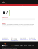
PMKG-LT
Low-Profile Tee Connection Kit Installation Instructions
This component is an electrical device that
must be installed correctly to ensure proper
operation and to prevent shock or fire. Read these
important warnings and carefully follow all of the
installation instructions.
• To minimize the danger of fire from sustained
electrical arcing if the heat ing cable is
damaged or improperly installed, and to
comply with the requirements of nVent, agency
certifications, and National Electrical Codes,
ground-fault equipment protection must be
used. Arcing may not be stopped by conven-
tion al circuit breakers.
• Component approvals and performance are
based on the use of nVent-specified parts only.
Do not use substitute parts or vinyl electrical
tape.
• The black heating cable core is conductive
andcan short. It must be properly insulated
and kept dry.
• Damaged bus wires can overheat or short.
Donot break bus wire strands when scoring
thejacket or core.
• Keep components and heating cable ends dry
before and during installation.
• Bus wires will short if they contact each other.
Keep bus wires separated.
• Use only fire-resistant insulation materials, such
as fiberglass wrap or flame-retardant foam.
WARNING:
DESCRIPTION
The nVent RAYCHEM PMKG-LT is a NEMA Type 4X rated tee
kit designed for use with RAYCHEM BTV-CR, BTV-CT, QTVR-CT,
LBTV2-CT, and KHP-CR parallel heating cables. It is designed
to be placed on the pipe, under the insulation and cladding.
For additional information contact your nVent representative
or call (800) 545-6258.
TOOLS REQUIRED
• Wire cutters • Screwdriver
• Needlenose pliers • Utility knife
ADDITIONAL MATERIALS REQUIRED
• Three grommets: (1)
PMK-GK-10 P/N 222724-000 (Package of ten grommets)
• Glass cloth tape
– GT-66 Installation temperature above 40°F (4°C)
– GS-54 Installation temperature above –40°F ( –40°C)
(1) Required for LBTV2 (see step 1)
Item Qty Description
A 1 Body
B 3 Pressure plates with captive screws
C 3 Red grommets (not for use with LBTV2)
D 2 Gaskets
E 2 Covers with captive screws
F 1 Label
A
F
TEE
ELECTRIC TRACED
B
C
E
D
APPROVALS
KIT CONTENTS
-W
Class I, Div. 2, Groups A, B, C, D
Class II, Div. 2, Groups F, G
Class III
KHP-CR heating cables only
BTV-CR, BTV-CT, QTVR-CT and LBTV2-CT heating cables only
Hazardous Locations
Nonhazardous Locations

nVent.com | 3
2 | nVent.com
BTV-CR, BTV-CT, QTVR-CT, LBTV2-CT, KHP-CR
Bus wire
Conductive core
Inner jacket
Braid
Outer
jacket
1
12 in
(30 cm)
12 in
(30 cm)
center-line of
connection body
2
3
4 in
(100 mm)
Do not cut braid.
1
2
4 5
3
• Identify heating cable type.
• Select correct grommet from table below.
Heating Cable Type Grommet
BTV, QTVR -CR or -CT RED
LBTV2 -CT K (Orderseparately)
KHP -CR RED
• Allow extra heating cable as shown.
• Lightly score outer jacket.
• Bend heating cable to break jacket
at score, then peel off jacket.
• Slide parts onto heating cable in order shown.
• Push braid back to create a pucker.
• At pucker use a screwdriver to
open braid.
• Bend heating cable and work it
through opening in braid.
WARNING: Use of the wrong grommet can result in
leaks, cracked components, shock or dielectric failure,
and will invalidate approvals and certifications.

nVent.com | 3
2 | nVent.com
1/4 in
(5 mm)
3
1
2
3
3
1
2
3
Trim
Do not allow braid
to contact bus wires
6
8
10 11
3 1/2 in
(89 mm)
Do not cut bus wires
7
9
• Pull braid tightly to center of cable to make a pigtail.
• Notch core.
• Twist back and peel bus wire from core.
• Push heating cable number 3 into body. Slide grommet
into cavity and seat.
• Tighten pressure plate screws to body.
• Lightly score inner jacket.
• Peel off jacket.
• Score core between bus
wires and inner jacket.
• Bend and snap core.
• Peel core free
from bus wire.
• Clean bus wires.
• Push braid wires away
from bus wires.
• Remove screws,
lockwashers and clamps.
• Position wires on blocks.
• Refit clamps, lockwashers,
screws, and tighten.
• Trim all extra lengths
of wire and remove any
loose wires.

nVent.com | PB
4 | nVent.com
2
3
B
AII
1
2
1
12
14 15
Trim
Trim
2
3
B
AII
1
Do not allow braid
to contact bus wires
13
• Turn over tee body.
• Push heating cables 1 and 2 into body, slide grommets
into cavities and seat.
• Tighten pressure plate screws to body.
• Remove release lining, if present, from gasket.
• Position gaskets and covers on body.
• Tighten covers to body.
• Remove screws, lockwashers and clamps.
• Push braid wires away from bus wires.
• Position wires on blocks.
• Refit clamps, lockwashers,
screws, and tighten.
• Trim all extra lengths of wire
and remove any loose wires
.
• Tape tee to pipe.
• Loop and tape extra heating cable to pipe.
• Install label on outside of cladding.
North America
Tel +1.800.545.6258
Fax +1.800.527.5703
Europe, Middle East, Africa
Tel +32.16.213.511
Fax +32.16.213.604
Asia Pacific
Tel +86.21.2412.1688
Fax +86.21.5426.3167
Latin America
Tel +1.713.868.4800
Fax +1.713.868.2333
©2018 nVent. All nVent marks and logos are owned or licensed by nVent Services GmbH or its affiliates. All other trademarks are the property of their respective owners.
nVent reserves the right to change specifications without notice.
Raychem-IM-H54257-PMKGLT-EN-1805
nVent.com
PN 920059-000
/


