Inglis GR440LXMC0 Installation guide

Category
Cookers
Type
Installation guide
m M
9759923
e
with seff-cJeaning oven
Tip Over Hazard
A child or adult can tip the range and
be killed,
Connect anti-tip bracket to rear
range foot.
Reconnect the anti-tip bracket, if the
range is moved.
FaiJure to follow these instructions can
result in death or serious burns to
Pages
%-_
[]
[]
Before you start
Product dimensions
Cabinet dimensions/requirements
Electrical requirements
Installation steps
Check operation
if range does not operate
if you need assistance/service
Moving the range
children and aduJts.
ww, w,,wh Mpool ,corn
Read and save these
IMPORTANT:
Installer: Leave Installation
hstructions with the homeowner,
Homeowner: Keep installation
instructions for future reference,
Read and save these instructions for
local electrical inspector's use,
Write down the model and serial
numbers before installing range,
Both numbers are listed on the
model/serial rating plate located
on the oven frame behind the
storage drawer panel,
Model #
Serial # Part No. 9759923
Before you start...
Your safety and the safety of
others are very important.
We have provided many important safety
messages in this manual and on your
appliance. Always read and obey all
safety messages.
This is the safety alert symbol.
This symbol alerts you to
potential hazards that can kill
or hurt you and others.
All safety messages will follow the safety
alert symbol and either the word
'DANGER" or ' WARNING." These
words mean:
You can be killed or seriously injured
if you don't immediately follow
instructions.
You can be kitled or seriously injured
if you don't follow instructions.
All safety messages will tell you what the
potential hazard is, tell you how to
reduce the chance of injury, and tell you
what can happen if the instructions are
not followed.
IMPORTANT: Observe all governing codes
and ordinances. Failure to meet codes
and ordinances could lead to fire or
electrical shock.
Proper installation is your responsibilit%
A qualified technician must install this
range, Make sure you have everything
necessary for correct instdhtion, It is the
instdler's responsibility to comply with
installation clearances specified on the
model/serial rating phte, The model/serial
rating plate is located on the oven frame
behind the storage drawer panel,
Check location where range will be
installed,The range should be located for
convenient use in kitchen,
To eliminate the risk of burns or fire by
reaching over heated surface units,
cabinet storage space located above the
surface units should be avoided. If
cabinet storage is to be provided, the risk
can be reduced by installing a range
hood that projects horizontally a
minimum of 5 inches beyond the bottom
of the cabinets.
All openings in the wall or floor where
ranges is to be installed must be sealed.
Cabinet opening dimensions that are
shown must be used. Given dimensions
are minimum clearances.
Grounded electrical outlet is required.
See "Electrical requirements" section,
Mobile home installation
The installation of this range must
conform with the Manufactured Home
Construction and Safety Standard,Title
24 CFR, Part 3280 [formerly the Federal
Standard for Mobile Home Construction
and Safety, Title 24, HUD (Part 280)] or,
when such standard is not applicable, the
Standard for Manufactured Home
Installations, ANSI A225J/NFPA 501A%
or with local codes.
When this range is installed in a mobile
home, it must be secured to the floor
during transit. Any method of securing
the range is adequate as long as it
conforms to the standards listed above,
FouFwire power supply cord or cable
must be used in a mobile home
installation, The appliance wiring will
need to be revised, See "Four-wire
electrical connection" section,
The floor anti-tip
bracket must be
installed.To install the
anti-tip bracket
shipped with the
range, see Page 4 and
the anti-tip bracket template,
Copies of the standards listed may be obtained
from:
National Fire Protection Association
One Batterymarch Park
Quincy, Massachusetts, 02269
ToMs needed:
Assemble the required tools and parts
before starting installation. Read and
follow the instructions provided with any
tools listed here,
o level
, flat-blade screwdriver
,3/8" drive ratchet
.3/8" and 5/16" nut drivers
. hand or electric drill
. channel lock pliers
®measuring tape or ruler
wood floors: 1/8" drill bit
®concrete/ceramic floors:
3/16" carbide4ipped masonr drill bit
(Hammer may be needed for anchors,)
Parts suppfied:
Not shown:
literature pack
_% 2 plastic
anchors
floor-mou nted
anti-tip bracket
2 screws
(#10 x 1-1/2")
Brackets must be securely mounted to sub-floor.
Thickness of flooring may require longer screws to
anchor bracket to sub-floor. Longer screws are
available from your local hardware store.
Product dimensions
27-1/8" (68.9 cm)
depth with handle
46-7/8"
(119.! cm)
overall
height
36"
(91.4 era)
cooktop
height
24-13/16"
(63 cm)
29-7/8" (75.9 cm) width \
Electrical requirements
if codes permit and a separate ground
wire is used, it is recommended that a
quaiified eiectrician determine that the
ground path and wire gauge are in
accordance with iocai codes.
This range must be connected to a
grounded metal, permanent wiring
system.
Check with a qualified electrician if you
are not sure range is properly grounded.
Do not ground to a gas pipe.
Do not have a fuse in the neutral or
ground circuit.
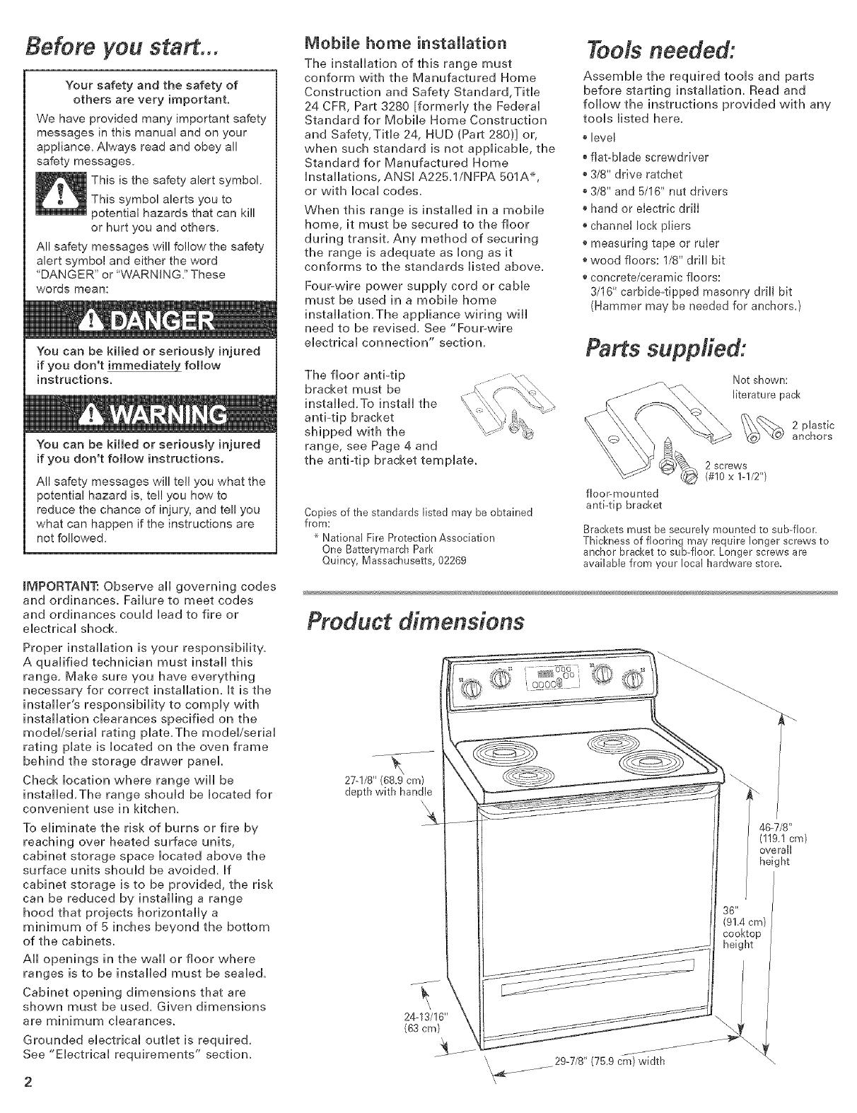
Range must be connected to the proper
electrical voltage and frequency as
specified on the model/serial rating plate.
(The model/serial rating plate is located
on the oven frame behind the storage
drawer panel.)
[_ A four-wire or three-wire, single+
phase, 120/240+volt, 60-Hz, AC+only,
electrical supply (or three-wire or four-
wire 120/208+volt if specified on the
model/serial rating plate) is required on a
separate, 40 amp circuit, fused on both
sides of the line.
[_ A time-delay fuse or circuit breaker is
recommended.
[_ The range can be connected directly
to the fused disconnect (or circuit breaker
box) through flexible armored conduit.
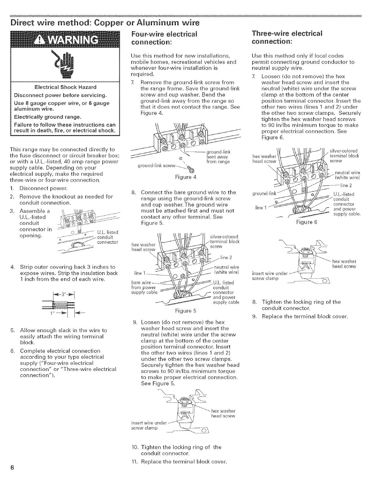
This range can be direct wired to a four-
wire or three-wire aluminum wiring
system. See "Direct wire method: Copper
or Aluminum wire" section.
Allow two to three feet of slack in the line
so that it can be moved if servicing is
ever necessary.
A U.L.+listed conduit connector must be
provided at each end of the power supply
cane (at the range and at the junction
box).
Wire sizes and connections must conform
with the rating of the range (40 amps).
[_ The wiring diagram is [ocated on the
back of the range or on the inside of the
storage drawer in a clear piasfic bag.
Recommended ground method
It is the persona[ responsibility and
obligation of the customer to contact a
qualified eiectrician to assure that the
eiectrica[ instaiiation is adequate and is in
conformance with the Nationa[ Eiectrica[
Code, ANS[/NFPA 70 -- [atest edition _
and all[ [oca[ codes and ordinances.
Power supply cord is not supplied, but is
available through your local electrical
supply house,
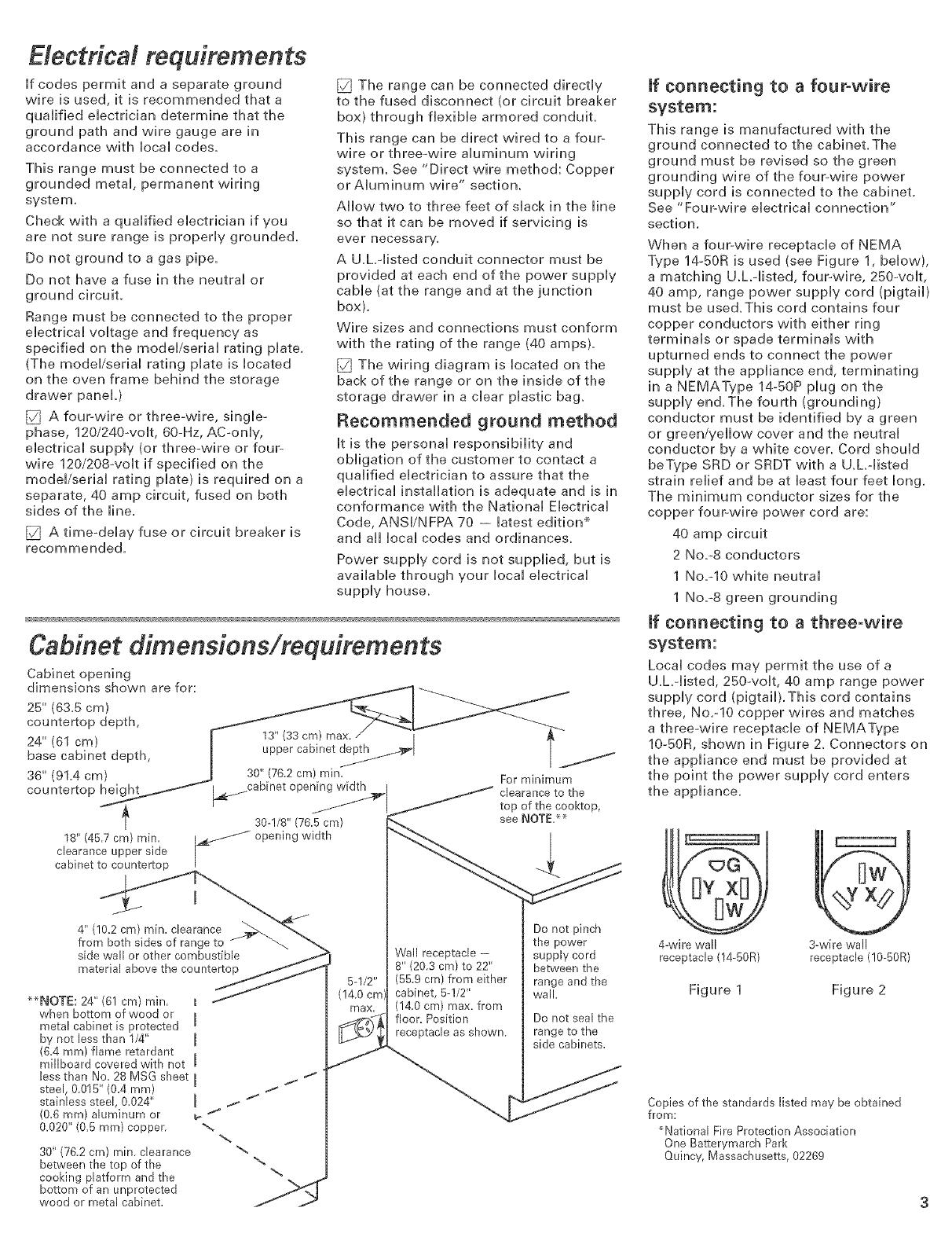
cabinet to countertop
4" (10.2cm) min. clearance
from both sides of range to
side wall or other combustible
material above the countertop
++NOTE: 24" (61 cm) min. t
when bottom of wood or I
metal cabinet is protected
by not less than I/4" I
(6.4 mm) flame retardant
millboard covered with not I
less than No. 28 MSG sheet I
steel, 0.015" (0.4 ram)
stainless steel, 0.024" I
(0.6 mm) aluminum or _
0.020" (0.6 ram) copper. "_
30" (76.2 cm) rain. clearance "_
between the top of the
cooking platform and the
bottom of an unprotected
wood or metal cabinet.
Wall receptacle -
8" (20.3 cm) to 22"
(55.9 cm) from either
cabinet, 5-I/2"
(14.0 cm) max. from
floor. Position
receptacle as shown.
mfconnecting to a four-wire
system:
This range is manufactured with the
ground connected to the cabinet.The
ground must be revised so the green
grounding wire of the four-wire power
supply cord is connected to the cabinet.
See "Four-wire electrical connection"
section.
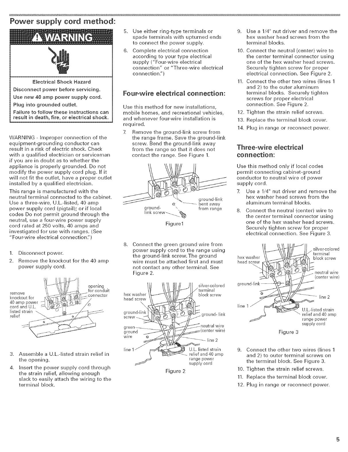
When a four-wire receptacle of NEMA
Type 14-50R is used (see Figure 1, below),
a matching U,h+iisted, four+wire, 250+volt,
40 amp, range power supply cord (pigtail)
must be used,This cord contains four
copper conductors with either ring
terminals or spade terminals with
upturned ends to connect the power
supply at the appliance end, terminating
in a NEMAType 14-50P plug on the
supply end,The fourth (grounding)
conductor must be identified by a green
or green/yellow cover and the neutral
conductor by a white cover, Cord should
beType SRD or SRDT with a U,h-listed
strain relief and be at bast four feet long,
The minimum conductor sizes for the
copper four-wire power cord are:
40 amp circuit
2 No,+8 conductors
1 No,+10 white neutral
1 No,°8 green grounding
If connecting to a three-wire
system:
Local codes may permit the use of a
U.h-listed, 250-volt, 40 amp range power
supply cord (pigtail).This cord contains
three, No.-10 copper wires and matches
a three-wire receptacle of NEMAType
10+50R, shown in Figure 2. Connectors on
the appliance end must be provided at
the point the power supply cord enters
the appliance.
Do not pinch
the power 4-wire wall 3-wire wall
supply cord receptacle (14-50R) receptacle (I0-60R)
between the
range and the
wall. Figure 1 Figure 2
Do not seal the
range to the
side cabinets.
Copies of the standards listed may be obtained
from:
+National Fire Protection Association
One Batterymarch Park
Quincy, Massachusetts, 02269
Now start...
Excessive Weight Hazard
Use two or more people to move and
install range.
Failure to do so can result in back or
other injury.
1[] Remove shipping matedab, tape
and protective film from range. Keep
cardboard bottom and shipping base
under range. Remove oven racks and
parts package from inside oven.
Tip Over Hazard
A child or adult can tip the range and
be killed.
Connect anti-tip bracket to rear
range foot.
Reconnect the anti-tip bracket, if the
range is moved.
Failure to follow these instructions can
result in death or serious burns to
children and adumts.
[] Contact a qualified floor covering
installer for the best procedure for
drilling mounting hobs through your
type floor covering.
EJectricaJ connection
[] Remove the terminal block cover
screws located on the back of range, Puii
cover down and towards you to remove
cover from range,
Pull cover down
and towards you
to remove.
terminal
block cover
_2 mounting
tabs, each side
/
hex-head screws
[] Remove storage drawer. Use a 3/8"
drive ratchet to lower rear leveling legs
one-half turn. Use channel lock pliers to
lower front leveling legs one-half turn.
rear leveling leg front leveling leg
flooring, longer screws may
be necessary to anchor the bracket to the
sub°floor. Longer screws are available
from your local hardware store.
Check that range is on cardboard
shipping base to protect floor covering.
[] Depending on your electrical
supply, make the four-wire or three-wire
connection to the range following the
"Power supply cord method" or "Direct
wire method" instructions for copper
wire or aluminum wire depending on the
connection needed.
Power suppJy cord method:
Electrical Shock Hazard
Disconnect power before servicing.
Use new 40 amp power supply cord.
Plug into grounded outlet.
Failure to follow these instructions can
result in death, fire, or electrical shock.
WARNING - improper connection of the
equipment=grounding conductor can
result in a risk of electric shock, Check
with a qualified electrician or serviceman
if you are in doubt as to whether the
appliance is properly grounded, Do not
modify the power supply cord plug, If it
will not fit the outlet, have a proper outlet
installed by a qualified electrician,
This range is manufactured with the
neutral terminal connected to the cabinet,
Use a threeowire, U,hqisted, 40 amp
power supply cord (pigtaib; or if local
codes Do not permit ground through the
neutral, use a fouPwire power supply
cord rated at 250 volts, 40 amps and
investigated for use with ranges, (See
"Four-wire electrical connection/')
1, Disconnect power,
2, Remove the knockout for the 40 amp
power supply cor&
remove
knockout for
40 amp power
cord and U.L
listed strain
relief
opening
for conduit
5_
6_
Use either ring-type terminals or
spade terminals with upturned ends
to connect the power supply,
Complete electrical connection
according to your type electrical
supply ("Four-wire electrical
connection" or "Threeowire electrical
connection,")
FouPwire eUectrical connection:
Use this method for new installations,
mobile homes, and recreational vehicles,
and whenever four-wire installation is
required,
7, Remove the ground-link screw from
the range frame, Save the ground-link
screw, Bend the ground-link away
from the range so that it does not
contact the range, See Figure 1,
9, Use a 1/4" nut driver and remove the
hex washer head screws from the
terminal blocks,
10, Connect the neutral (center) wire to
the center terminal connector using
one of the hex washer head screws,
Securely tighten screw for proper
electrical connection, See Figure 2,
11, Connect the other two wires (lines 1
and 2) to the outer aluminum
terminal blocks, Securely tighten
screws for proper electrical
connection, See Figure 2,
12, Tighten the strain relief screws,
l& Replace the terminal block cover,
14, Plug in range or reconnect power,
Three-wire eUectrical
connection:
ground- \ from range
linkscrew_@
Figure1
Use this method only if local codes
permit connecting cabinetoground
conductor to neutral wire of power
supply cord,
7, Use a 1/4" nut driver and remove the
hex washer head screws from the
aluminum terminal blocks,
Connect the neutral (center) wire to
the center terminal connector using
one of the hex washer head screws.
Securely tighten screw for proper
electrical connection. See Figure 3.
8_
Connect the green ground wire from
power supply cord to the range using
the groundqink screw.The ground
wire must be attached first and must
not contact any other terminal. See
Figure 2.
silver-colored
hex washer
head s_ew
silver-colored
block screw
wire
(center wire)
hex washer
head screw
\
g
ground
wire
block screw
_.ground-link
line 2
line
Figure 3
line 2
U.h-I[sted strain
relief and 40 amp
range power
supply cord
3,
4,
Assemble a U.L.qisted strain relief in
the opening.
Insert the power supply cord through
the strain relief, allowing enough
slack to easily attach the wiring to the
terminal block.
Figure 2
U.L listed strain
relief and 40 amp
range power
supply cord
9. Connect the other two wires (lines 1
and 2) to outer terminal screws on
the terminal block See Figure 3.
10. Tighten the strain relief screws.
11. Replace the terminal block cover.
12. Hug in range or reconnect power.
Direct wire method: Copper or Aluminum wire
Four=wire electrical Three-wire eUectrica[
connection: connection:
Electrical Shock Hazard
Disconnect power before servicing.
Use 8 gauge copper wire, or 6 gauge
aluminum wire.
Electrically ground range.
Failure to follow these instructions can
result in death, fire, or electrical shock.
This range may be connected directly to
the fuse disconnect or circuit breaker box;
or with a U.hdisted, 40 amp range power
supply cable. Depending on your
electrical supply, make the required
three-wire or four-wire connection.
1. Disconnect power.
2. Remove the knockout as needed for
conduit connection.
4,
S,
6,
Assemble a
U.L.-listed
conduit
connector in
opening.
Strip outer covering back 3 inches to
expose wires. Strip the insulation back
1 inch from the end of each wire.
Allow enough slack in the wire to
easily attach the wiring terminal
block,
Complete electrical connection
according to your type electrical
supply ("Four-wire electrical
connection" or "Three-wire electrical
connection").
Use this method for new installations,
mobile homes, recreational vehicles and
whenever four-wire installation is
required.
7, Remove the ground-link screw from
the range frame. Save the ground-link
screw and cup washer. Bend the
grounddink away from the range so
that it does not contact the range. See
Figure 4.
,, from range
grounddink screw---.._%
Figure 4
8_
Use this method only if local codes
permit connecting ground conductor to
neutral supply wire.
7, Loosen (do not remove) the hex
washer head screw and insert the
neutral (white) wire under the screw
damp at the bottom of the center
position terminal connector, insert the
other two wires dines 1 and 2) under
the other two screw clamps. Securely
tighten the hex washer head screws
to 90 in/Ibs minimum torque to make
proper electrical connection. See
Figure 6.
I silver-colored
hex washer
head screw screw
\
\
neutral wire
2
Connect the bare ground wire to the g U.Ldisted
range using the ground-link screw
connector
and cup washer.The ground wire line 1 and power
must be attached first and must not
contact any other terminal. See supply cable.
Figure 5. Figure 6
_ex2_acSr_ silver-colored
/terminal block
screw
, line 2
line 1 (white wire}
U.L listed
from power
supply cable connector
and power
supply cable
Figure 5
9. Loosen (do not remove) the hex
washer head screw and insert the
neutral (white) wire under the screw
clamp at the bottom of the center
position terminal connector, insert
the other two wires (lines 1 and 2)
under the other two screw clamps.
Securely tighten the hex washer head
screws to 90 in/Ibs minimum torque
to make proper electrical connection.
See Figure 5.
headscrew
insert wire under _'J<_
clampscrew
_ j--
IL_,_JI _ hexwasher
insert wire under _, /_ head screw
screw clamp
8, Tighten the locking ring of the
conduit connector,
9, Replace the terminal block cover.
10, Tighten the locking ring of the
conduit connector.
11. Replace the terminal block cover,
6
Operating position
Before moving range across floor, check
that range is still on cardboard shipping
base to protect floor covering.
7[] Make sure the anti-tip bracket is
installed:
Look for the anti-tip bracket securely
attached to floor.
Slide range back so rear range foot
is under anti-tip bracket.
8[] If installing the range in a mobile
home, you must secure the range to the
floor. Any method of securing the range
is adequate as long as it conforms to the
standards in the "Mobile home
installation"section.
9_ Place rack in oven. Place level on
rack, first side to side; then front to back.
If range is not level, pull range forward
until rear leveling leg is removed from
the anti4ip bracket. Use 3/8" drive ratchet
and channel lock pliers to adjust leveling
legs up or down until range is level. Push
range back into position. Check that rear
leveling leg is engaged in anti4ip
bracket.
NOTE: Oven must be level for
satisfactory baking conditions,
Replace the storage drawer or
lower panel.
1_ Reconnect power.
Check operation
2_ Check the operation of the
cooktop elements:
Push in and turn each surface unit control
knob to "Hi" position. Check the
operation of the cooktop elements and
indicator lights.
CO FRONT OFF
@O
3_ Check the operation of the
oven:
If your oven has one of the two types of
electronic controls shown:
Press the "BAKE" pad.
Depending on model, the "BAKE"
and "TEMP" indicators will light
and "350" will appear in the display
or, the "BAKE" indicator will light
and "350" will appear in the display.
2_
_The "START" indicator will begin
flashing after 5 seconds.
Press the "START/ENTER" pa&
_The "ON" indicator will light.
_The "TEMP" indicator will turn off.
*The display wiii show the automatic
countdown time needed to preheat
the oven to the selected temperature
("350") and begin counting down.
oThe bottom element should glow
red_
_The upper element should become
hot, but not glow red.
3. Press the "OFF/CANCEL' pad.
NOTE:The oven will not go through
preheat if the oven temperature is above
170° F; instead, the "TEMP" indicator will
light and the selected temperature will
appear in the display.
4. Press the "CUSTOM BROIL' pa&
* Depending on model, the "BROIL'
and "TEMP" indicators will light
and "500" will appear in the display
or, the "BROIL' indicator will light
and "500" will appear in the display.
_The "START" indicator will begin
flashing after 5 seconds,
5. Press the "START/ENTER" pad.
®The "ON" indicator will light.
_The upper element will glow re&
6. Press the "OFF/CANCEL' pad.
You have just finished installing
your new range.To get the
most efficient use from your
range, read your Use & Care
Guide. Keep Installation
Instructions and Guide close to
range for easy reference. The
instructions will make installing
the range in another home as
easy as the first installation.
Moving the range
Tip Over Hazard
A child or adumt can tip the range and
be kiHed.
Connect anti-tip bracket to rear
range foot.
Reconnect the anti-tip bracket, if the
range is moved.
Failure to follow these instructions can
resumt in death or serious burns to
children and adults.
When moving range, sH[de range onto
cardboard or hardboard to prevent
damaging the floor covering.
If removing the range is necessary for
cleaning or maintenance:
1. UnpHug range or disconnect power.
2. SH[de range forward to compHete
cHean[ng or maintenance.
3. Make sure the ant[4[p bracket is
[nstaHHed:
Look for the antPfip bracket securely
attached to floor,
SH[de range back so rear range foot
is under anti-tip bracket,
4, Check that range is HeveH,
5, Hug in range or reconnect power,
If range does not
operate:
Check that the circuit breaker is not
tripped or the house fuse blown.
[_ Check that the power suppHy cord is
pHugged into the outlet.
[_ See Use and Care Guide for
troubHeshooting Hist.
ff you need assistance:
If you have questions about operating,
cHeaning or maintaining your range:
[_ Refer to Use and Care Guide.
[_ Call[ the Customer [nteraction Center.
Check your Use and Care Guide for a
toHFfree number to call[ or call[ the
deaHer from whom you purchased
this appHiance.The deaHer is [isted in
theYeHHow Pages of your phone
directory under "AppHiances --
HousehoHd -- Major -- Service and
Repair."
ff you need serw'ce:
Maintain the quality built into your range
by caHHing an authorized service company.
To obtain the name and number of the
authorized service company:
[_ Contact the deaHer from whom you
purchased your range; or
[_ Look in theYeHHow Pages of your
teHephone directory under
"AppHiances -- HousehoHd -- Major
-- Service and Repair;" or
[_ CaHHthe Customer Interaction Center.
The toHH-free number is Histed in your
Use and Care Guide.
When you caH[, you will[ need:
[_ The range mode[ number.
[_ The range seria[ number.
Both numbers are Histed on the
modeH/seria[ rating pilate [ocated on the
oven frame behind the storage drawer
pane[.
Part No. 9759923 Printed in U.S.A.
_, 2004 Whirlpool Corporation Benton Harbor, Michigan 49022 04/2004
  • Page 1 1
  • Page 2 2
  • Page 3 3
  • Page 4 4
  • Page 5 5
  • Page 6 6
  • Page 7 7
  • Page 8 8

Inglis GR440LXMC0 Installation guide

Category
Cookers
Type
Installation guide

Ask a question and I''ll find the answer in the document

Finding information in a document is now easier with AI