Page is loading ...

WHITE-RODGERS
FAILURE TO READ AND FOLLOW ALL INSTRUCTIONS CAREFULLY BEFORE
INSTALLING OR OPERATING THIS CONTROL COULD CAUSE PERSONAL INJURY
AND/OR PROPERTY DAMAGE.
Model No. Voltage
36C21U
36C21
36C21A
Current
D.C.
.23 Amp
.035 Amp
750 MV
24 volts
120 volts
WHITE-RODGERS DIVISION
EMERSON ELECTRIC CO.
9797 REAVIS ROAD
ST. LOUIS, MISSOURI 63123-5398
Printed in U.S.A.
PART NO. 37-4048B
Replaces 37-4048, 37-2570, 37-1972
9615
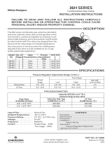
36C21 Series
Main Gas Valves
INSTALLATION INSTRUCTIONS
Operator: Save these instructions for future use!
These Gas Valves control the flow of gas to the main
burner under command of a room thermostat. They are
suitable for use on all gases and may be used with all
types of gas heating equipment. They may be mounted in
any position except upside down.
Some parts of this gas valve are also used to make more
complex combination gas controls. Disregard the nota-
tions “Pilot”, “Pilot Adj.” and “Vent ”. Although these
notations do appear on the valve, they are not functional
on model 36C21 Series controls.
DESCRIPTION
NOTE
SPECIFICATIONS
Electrical Rating:
Main Valve
Maximum Pressure Rating:
14" W.C. (
1
⁄2 lb. per sq. in.)
Ambient Temperature: -40° to 175°F
Do not use this valve on indoor LP gas furnaces
except with 100% shut-off system.
Mounting: Any position except upside-down
CAUTION
!
PIPE SIZES/CAPACITIES
Pipe Size
(inches)
Capacity (BTU/hr) at
1” pressure drop across valve
1
⁄
2
” x
3
⁄
8
”
1
⁄
2
” x
1
⁄
2
”
1
⁄
2
” x
3
⁄
4
”
3
⁄
4
” x
3
⁄
4
”
100,000
230,000
230,000
280,000
162,000
372,600
372,600
453,600
Nat. Gas
(1000 BTU/cu. ft.,
64 Sp. Gr.)
LP Gas
(2500 BTU/cu. ft.,
1.53 Sp. Gr.)
MOUNTING POSITIONS:
Upright, 90° from upright or vertical
INLET BOSS
UP OR DOWN
UPRIGHT
LEFT OR RIGHT
360°

2
DO NOT BEGIN INSTALLATION UNTIL YOU READ
THE FOLLOWING PRECAUTIONS.
PRECAUTIONS
1. Failure to turn off electric or main gas supply
to heating system could cause personal in-
jury and/or property damage by shock, gas
suffocation, fire, and/or explosion.
2. Do not use this control on circuits exceeding
specified voltage. Higher voltage will damage
the control and may cause shock or fire
hazard.
3. NEVER USE FLAME OR ANY KIND OF SPARK
TO CHECK FOR GAS LEAKS–COULD CAUSE
FIRE AND/OR EXPLOSION.
4. DO NOT USE WIRE JUMPER on pilot sys-
tems, such as standing pilot, proven pilot, or
spark-to-pilot ignition–a fire and/or explosion
may result.
5. Do not use a control set for natural gas with
LP gas, or a control set for LP gas with natural
gas. Personal injury and/or property damage,
gas suffocation, fire, and/or explosion may
result.
1. Do not short out terminals on gas valve or
primary control to test. Short or incorrect
wiring can cause equipment damage, prop-
erty damage, and/or personal injury.
2. This control is not intended for use in loca-
tions where it may come in direct contact with
water. Suitable protection must be provided
to shield the control from exposure to water
(dripping, spraying, rain, etc.).
WARNING
!
If you do not follow these instructions exactly, a fire or explosion may
result, causing property damage, personal injury or loss of life.
CAUTION
!

3
SYSTEM WIRING
To prevent electrical shock and/or equipment
damage, disconnect electrical power to system at
main fuse or circuit breaker box until installation
is complete.
All wiring should be installed in accordance with local
and national electrical codes and ordinances.
Always check that the electrical power supply used
agrees with the voltage and frequency shown on the
gas control.
These typical wiring diagrams (figs. 2 and 3) show only the
terminal identification and wiring hook up. Always refer to
wiring instructions provided by equipment manufacturer
for system hook-up and operation.
INSTALLATION
MAIN PIPING CONNECTIONS
Failure to turn off electric or main gas supply to
heating system could cause personal injury and/
or property damage by shock, gas suffocation,
fire, and/or explosion.
1. Turn off electrical power to the system at the fuse box
or circuit breaker. Also turn off the main gas supply.
2. If replacing an existing valve, disconnect all plumbing
and electrical connections from the old control.
3. The control may be installed in any orientation except
upside down. The arrow on the valve indicates the
direction of gas flow through the control.
4. You should use new pipe that is properly chamfered,
reamed, and free of burrs and chips. If you are using
old pipe, be sure it is clean and free of rust, scale,
burrs, chips, and old pipe joint compound.
5. Apply pipe joint compound (pipe dope) or teflon tape
that is approved for all gases, only to the male
threads of the pipe joints. DO NOT apply com-
pound or teflon tape to the first two threads (see fig. 1
for typical piping connections).
6. If you are using a vise or open-end wrench to hold the
valve while installing piping, do not tighten exces-
sively, as this may damage the valve.
7. See SYSTEM WIRING when making electrical con-
nections. After all gas and electrical connections are
completed, turn gas on and check for gas leaks with
leak detection solution or soap suds. Bubbles forming
indicate a leak. SHUT OFF GAS AND FIX ALL
LEAKS IMMEDIATELY.
All piping must comply with local codes, ordinances,
and/or national fuel gas codes.
Thermostat
24 VAC
Gas
Valve
High
Limit
36C21
Valve
Automatic
Pilot
Figure 3. Wiring for 36C21 and 36C21A Models
NOTE
WARNING
!
CAUTION
!
NOTE
Piped Gas
Supply
Piped Gas
Supply
Tubing Gas
Supply
NOTE: ALWAYS INCLUDE A
DRIP LEG IN PIPING
Figure 1. Typical gas valve piping
Horizontal
Drop
Gas Valve
3 in.
minimum
Gas Valve
Riser
3 in.
minimum
Drop
Horizontal
Riser
Gas Valve
3 in.
minimum
High
Limit
To Pilot
Generator
TH
TH-TR
TR
Thermostat
Gas Valve
Terminal Panel
ALL WIRING
MUST BE
N.E.C. CLASS 1
Figure 2. Wiring for 36C21U

PILOT GAS ADJUSTMENT
If the pilot flame is low and does not engulf the bulb of the
mercury flame sensor, the system will not energize the
main valve. If pilot gas pressure is too high, gas will sputter
past the ignition electrode, and may not ignite. High pilot
gas pressure may also cause the flame to lift off the
burner, causing the flame sensor bulb to sense "low" heat.
To adjust the pilot gas pressure:
Remove the cover screw (see fig. 4).
To REDUCE pilot pressure, turn the pilot adjust screw
(beneath the cover screw) clockwise.
To INCREASE pilot pressure, turn the pilot adjust
screw counterclockwise.
Replace and tighten cover screw.
ADJUSTMENT
Pilot Adjust
Cover Screw
Gasket
Pilot
Adjust
Screw
Figure 4. Pilot gas adjustment
PILOT LIGHTING
Before lighting the pilot burner flame, remove one of pilot
generator leads from the valve. This will prevent main gas
valve from opening during the pilot lighting procedure,
even if thermostat should be calling for heat.
If you need further information about this product, please write to
White-Rodgers Division, Emerson Electric Co.
9797 Reavis Road
St. Louis, MO 63123-5398
Attention: Technical Service Department
/